US7010219B2 - Coded picture data reproducing apparatus - Google Patents
Coded picture data reproducing apparatus Download PDFInfo
- Publication number
- US7010219B2 US7010219B2 US09/810,447 US81044701A US7010219B2 US 7010219 B2 US7010219 B2 US 7010219B2 US 81044701 A US81044701 A US 81044701A US 7010219 B2 US7010219 B2 US 7010219B2
- Authority
- US
- United States
- Prior art keywords
- picture data
- frame
- gop
- data
- reproduced
- Prior art date
- Legal status (The legal status is an assumption and is not a legal conclusion. Google has not performed a legal analysis and makes no representation as to the accuracy of the status listed.)
- Expired - Fee Related, expires
Links
- 230000002457 bidirectional effect Effects 0.000 claims 1
- 102100037812 Medium-wave-sensitive opsin 1 Human genes 0.000 abstract description 516
- 230000003287 optical effect Effects 0.000 abstract description 145
- 230000003252 repetitive effect Effects 0.000 abstract description 58
- 238000000034 method Methods 0.000 description 142
- 239000000872 buffer Substances 0.000 description 52
- 238000012545 processing Methods 0.000 description 39
- 239000000284 extract Substances 0.000 description 13
- 238000010586 diagram Methods 0.000 description 12
- 238000006243 chemical reaction Methods 0.000 description 8
- 239000004973 liquid crystal related substance Substances 0.000 description 8
- 238000012986 modification Methods 0.000 description 2
- 230000004048 modification Effects 0.000 description 2
- 239000004065 semiconductor Substances 0.000 description 2
- 239000000463 material Substances 0.000 description 1
Images


Classifications
-
- G—PHYSICS
- G11—INFORMATION STORAGE
- G11B—INFORMATION STORAGE BASED ON RELATIVE MOVEMENT BETWEEN RECORD CARRIER AND TRANSDUCER
- G11B27/00—Editing; Indexing; Addressing; Timing or synchronising; Monitoring; Measuring tape travel
- G11B27/005—Reproducing at a different information rate from the information rate of recording
- G11B27/007—Reproducing at a different information rate from the information rate of recording reproducing continuously a part of the information, i.e. repeating
-
- H—ELECTRICITY
- H04—ELECTRIC COMMUNICATION TECHNIQUE
- H04N—PICTORIAL COMMUNICATION, e.g. TELEVISION
- H04N9/00—Details of colour television systems
- H04N9/79—Processing of colour television signals in connection with recording
- H04N9/80—Transformation of the television signal for recording, e.g. modulation, frequency changing; Inverse transformation for playback
- H04N9/804—Transformation of the television signal for recording, e.g. modulation, frequency changing; Inverse transformation for playback involving pulse code modulation of the colour picture signal components
- H04N9/8042—Transformation of the television signal for recording, e.g. modulation, frequency changing; Inverse transformation for playback involving pulse code modulation of the colour picture signal components involving data reduction
-
- G—PHYSICS
- G11—INFORMATION STORAGE
- G11B—INFORMATION STORAGE BASED ON RELATIVE MOVEMENT BETWEEN RECORD CARRIER AND TRANSDUCER
- G11B2220/00—Record carriers by type
- G11B2220/20—Disc-shaped record carriers
- G11B2220/25—Disc-shaped record carriers characterised in that the disc is based on a specific recording technology
- G11B2220/2537—Optical discs
- G11B2220/2562—DVDs [digital versatile discs]; Digital video discs; MMCDs; HDCDs
-
- H—ELECTRICITY
- H04—ELECTRIC COMMUNICATION TECHNIQUE
- H04N—PICTORIAL COMMUNICATION, e.g. TELEVISION
- H04N5/00—Details of television systems
- H04N5/76—Television signal recording
- H04N5/84—Television signal recording using optical recording
- H04N5/85—Television signal recording using optical recording on discs or drums
Definitions
- the present invention relates to an apparatus for reproducing a coded picture data which is coded by using a predictive coding scheme, and more particularly to a coded picture data reproducing apparatus which is able to repetitively reproduce pictures between across frames by designating two any frames.
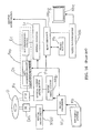
- FIG. 16 is a block diagram showing a conventional coded picture data reproducing apparatus.
- the coded picture data reproducing apparatus is comprised of a microprocessor Mp, a key input system Kb, a motor drive circuit Mdd, a disc drive motor Dm, a motor drive circuit Mdp, an optical pickup drive motor Pm, an optical pickup Pu, a syntax decoder Sx, an MPEG decoder Mpg, a frame buffer Fb, a video D/A (Digital to Analog) converter Vda and a front-end processor Fep.
- the front-end processor Fep is comprised of a data detecting circuit Ds and an error correction code (hereinafter referred to ECC) processing circuit Ec.
- ECC error correction code
- a turntable (not shown) for loading thereon the optical disc D is coupled to a rotor shaft of the disc drive motor Dm.
- the turntable is driven by the rotation of the rotor shaft and thus rotates the optical disc D loaded thereon.
- the video D/A converter Vda has an analog video signal output terminal which is capable of mechanically and electrically connecting to a signal line.
- the signal line is able to be both mechanically and electrically connected to a video input terminal of the monitor Mnt having a display device such as a liquid crystal device or a cathode-ray tube.
- the video D/A converter Vda forwards video signals to the monitor Mnt via the signal line.
- the monitor Mnt displays a picture image on its display screen according to the input video signal.
- the MPEG decoder Mpg has an output terminal which is capable of outputting a digital video signal.
- the microprocessor Mp is connected to the key input system Kb, the motor drive circuit Mdd and the motor drive circuit Mdp via the signal line.
- the microprocessor Mp is connected to the front-end processor Fep, the syntax decoder Sx and the MPEG decoder Mpg via the two-way bus line.
- microprocessor Mp controls circuit blocks connected thereto according to the command provided through a key-input system Kb.
- the microprocessor Mp forwards operation signals to the motor drive circuit Mdd and the motor drive circuit Mdp for making them rotate the optical disc D.
- the motor drive circuits Mdd and Mdp receive the operation signals from the microprocessor Mp and then forward driving signals to a disc drive motor Dm and an optical pickup drive motor Pm respectively coupled thereto.
- the disc drive motor Dm rotates the optical disc D at the rotation speed according to the driving signal.
- the optical pickup drive motor Pm moves the optical pickup Pu to the optical disc D in the radius direction according to the driving signal so that the optical pickup Pu search the picture data to be reproduced.
- the optical pickup Pu irradiates a laser beam to the signal recording surface of the optical disc D so as to obtain record signal based on the reflection light.
- the disc is recorded thereon picture data and addresses for indicating the record positions of the picture data. And the optical pickup Pu is moved according to the address to search the picture data to be reproduced.
- the optical pickup Pu searches the picture data to be reproduced, and then obtains the record signal corresponding to the picture data on the disc.
- the record signal picked up by the optical pickup Pu is forwarded to the data extracting circuit Ds which is contained in the front-end processor Fep, which is located in rear of the optical pickup Pu.
- the record signal is a wave-formed signal called a RF signal.
- the data extracting circuit Ds slices the RF signal at a specific timing so as to generate a rectangular wave-formed data signal.
- the data extracting circuit Ds forwards the data signal to the ECC processing circuit Ec on the rear.
- the data signal is record by executed a NRZI (Non Return to Zero Inverted) modulation at recording time.
- NRZI Non Return to Zero Inverted
- the ECC processing circuit Ec extracts a data signal from the invert interval of the data signal according to the NRZI demodulation rule, and performs the error correction of the data in each ECC block, then it forwards the data signal to the syntax decoder Sx located in rear of the circuit Ec.
- the syntax decoder Sx extracts the control data from the input data signal according to the command that is output from the microprocessor Mp. Further the syntax decoder Sx extracts the picture data and forwards the picture data to the MPEG decoder Mpg located in rear of the decoder Sx.
- the picture data is coded in the MPEG (Moving Picture Expert Group) system.
- the picture data is decoded in the MPEG decoder Mpg by the command output from the microprocessor Mp according to the decoding algorithm of pre-determined MPEG system.
- a frame buffer Fb which is connected to the MPEG decoder Mpg via the two-way bus line works as a work memory for temporarily storing the picture data when the MPEG coded picture data is decoded.
- the picture data temporarily stored in the frame buffer Fb is added a synchronizing data for every frame, then it is output to the video D/A converter Vda located in rear of the MPEG decoder Mpg.
- the MPEG decoder Mpg could output the picture data from the digital video signal output terminal as the digital video signal.
- the video D/A converter Vda converts the input picture data into the analog video signal.
- the video D/A converter Vda forwards the video signal which is converted to the analog signal to the monitor Mnt located in rear of the converter Vda, via the signal line.
- the monitor Mnt displays the picture image on a display device such as a liquid crystal device or a cathode-ray tube according to the input video signal.
- the picture image is reproduced in the way as mentioned above.
- FIG. 17 illustrates a data structure of the picture data of the MPEG system.
- the MPEG system is one of the predictive coding schemes based on the correlation between picture frames.
- the coded picture data is comprised of a plurality of groups of pictures (hereinafter referred to GOP).
- One GOP is comprised of a plurality of frames.
- Each frame is a coded picture data comprised of a picture data of an intraframe coded picture (I-picture), a plurality of interframe forward predictive coded pictures (P-pictures) and a plurality of bi-directional predictive coded pictures (B-pictures).
- I-picture intraframe coded picture
- P-pictures interframe forward predictive coded pictures
- B-pictures bi-directional predictive coded pictures
- the frames of the I-picture, P-picture and B-picture in the (N ⁇ 1)-th through (N+R)-th GOPs are arranged in the sequence of reproducing for convenience of explanation.
- the sequence of reproducing the frames of the pictures will be in the sequence of B ⁇ B ⁇ I ⁇ B ⁇ B ⁇ P ⁇ B ⁇ B ⁇ P ⁇ B ⁇ B ⁇ P.
- the data are transmitted or recorded in the sequence different from the above-mentioned sequence.
- the sequence for transmitting or recording the pictures will be in the sequence of I ⁇ B ⁇ B ⁇ P ⁇ B ⁇ B ⁇ P ⁇ B ⁇ B ⁇ P ⁇ B ⁇ B ⁇ B ⁇ B.
- the above-mentioned pictures are coded in a predetermined sequence according to the correlation between picture frames
- Each of the above-mentioned pictures is an example illustrating a part of the GOP. While the number of pictures is not limited to the above examples.
- the number of B-pictures preceding the I-picture may be three.
- the MPEG system is a coding system of the picture signal according to the predictive coding scheme.
- the data of each frame can be coded based on the correlation between the I-picture data which will be a frame standard of the moving picture and the P-picture data, B-picture data which are coded the difference of the I-picture data.
- an amount of change between frames of the moving picture before coding the frames is transformed to a motion-adaptive vector. Then the pictures of the frames are coded so as that they are predictively interpolated based on the motion-adaptive vector.
- the picture signal of the fame to be made as an I-picture is coded.
- the picture signal of the frame to be made as a P-picture based on its correlation to the coded I-picture is coded.
- the picture signal of the frame to be reproduced between the I-picture and the P-picture is coded as a B-picture based on its correlations to both the I-picture and the B-picture.
- sequence of coding the pictures are predetermined
- sequence of decoding the pictures are also predetermined.
- the picture data of the I-picture is decoded.
- the picture data of the P-picture is decoded by using the picture data of the decoded I-picture.
- the picture data of the B-pictures are decoded by using the picture data of the decoded I-picture and the P-picture.
- a reason for that the sequences of the coding and the decoding are predetermined is that the P-picture and B-pictures are coded in reference to the I-picture.
- the B-pictures are coded with reference to the I-picture and P-pictures, the B-picture have to be decoded by using the already decoded I-picture and B-pictures.
- the MPEG decoder Mpg temporarily stores the picture data for two GOPs in the frame buffer Fb and decodes the I-picture data Ip, the P-picture data Pp and the B-picture data B 1 , B 2 in the sequence as mentioned above. Accordingly, in a normal reproduction the P-picture data Pp belonging to the (N ⁇ 1)-th GOP, the B-picture data B 1 , B 2 and I-picture data Ip belonging to the N-th GOP are continuously decoded, then the picture data is temporarily stored in the frame buffer.
- the picture data corresponding to all of the frames in the N-th GOP and the (N ⁇ 1)-th GOP reproduced just before the N-th GOP are temporarily stored in the frame buffer Fb.
- the P picture data Pp which is temporarily stored in the frame memory Fb could be quoted, so that all of the frames are able to be decoded consecutively.
- start-frame and the end-frame for the repetitive reproduction are each marked as the position A and the position B in FIG. 17 .
- the optical pickup Pu decodes the P-picture data on the position B which belongs to the (N+R)-th GOP and searches the picture data on the position A which belongs the N-th GOP, thus it obtains the picture data of all of the fames belonging to the GOP as mentioned above.
- the MPEG decoder Mpg decodes the fetched picture data.
- the decoded P-picture data Pp corresponding to the P-picture frame which will be reproduced last in the (N ⁇ 1)-th GOP is essential for decoding the B-picture data B 1 , B 2 which correspond to the P-picture frame in the (N ⁇ 1)-th GOP and the I-picture frame in the N-th GOP. That is, the B-picture data B 1 , B 2 are not decoded by only the picture of the frame belonging to the N-th GOP.
- FIG. 18 illustrates a main routine in the operation of the conventional coded picture data reproducing apparatus.
- FIG. 19 illustrates a first sub-routine in the operation of the conventional coded picture data reproducing apparatus.
- FIG. 20 illustrates a second sub-routine in the operation of the conventional coded picture data reproducing apparatus.
- the programs shown by the flowcharts have been installed in the microprocessor Mp, as shown in a block diagram of FIG. 16 . That is, the microprocessor Mp controls the optical pickup Pu or the MPEG decoder Mpg in the coded picture data reproducing apparatus by the command according to the determination and/or processing steps, as shown in the flowchart, so as to execute the repetitive reproduction of pictures between the start-frame and the end-frame that are designated by the key input system Kb.
- S 61 denotes the “START” step of this program.
- step S 61 Following the “START” step S 61 , the process goes to step S 62 .
- step S 62 an initial value is substituted for the arguments N and R to search the MPEG encoded picture data in every GOP which are recorded on the optical disc D.
- the values N and R are stored in the internal memory of the microprocessor Mp.
- step S 62 the value N is set to the positive integer larger than 0, and the value R is set to ⁇ 1.
- step S 63 the process goes to step S 63 .
- step S 63 the optical pickup Pu is driven by the optical pickup drive motor Pm in order to search and obtain the picture data belonging to the (N+R)-th GOP.
- the picture data is decoded per each frame of the GOP in the MPEG decoder Mpg. After that all of the decoded picture data are temporarily stored in the frame buffer Fb.
- the picture data of the frames of the pictures are forwarded to the video D/A converter Vda on the rear in the reproducing sequence.
- the video D/A converter Vda starts the conversion of the input picture data into the analog video signal, and then sequentially forwards the converted video signal to the monitor Mnt via the signal line.
- the monitor Mnt starts the reproduction of the picture by the input video signal.
- the picture data fetched first will be the data belonging to the (N ⁇ 1)-th GOP.
- step S 64 the process goes to step S 64 .
- step S 64 at the reproducing time of the picture data belonging to the (N+R)-th GOP it is discriminated whether or not the start-frame (position A) is designated.
- the start-frame (position A) that is the start position for the repetitive reproduction is designated by pressing a start position designation key mounted through a key-input system Kb.
- step S 64 In case that the determination in step S 64 results in “YES”, i.e., when it is determined that there is a designation of the start-frame (position A), the process goes to the first sub-routine, as shown in FIG. 19 , via the node 1 .
- step S 64 determines whether there is no designation of the start-frame (position A). If the determination in step S 64 results in “NO”, i.e., when it is determined that there is no designation of the start-frame (position A), the process goes to step S 65 .
- step S 65 the argument R is incremented by 1 in order to search and obtain the picture data belonging to the next GOP.
- the picture data fetched next will be belonged in the N-th GOP.
- the value R is stored in the internal memory of the microprocessor Mp.
- the microprocessor Mp obtains the picture data belonging to the GOP based on the argument R by the optical pickup Pu.
- step S 66 the process goes to step S 66 .
- step S 66 it is discriminated whether or not the reproducing operation of the coded picture data reproducing apparatus is completed.
- the judgment if the reproducing operation is completed or not is determined whether or not an end key mounted through a key-input system Kb has been pressed.
- step S 66 If it is determined that a designation for an end-frame (position B) has been made, and then determined that the reproduction has completed, i.e., the determination has resulted in “YES” in step S 66 , the process goes to the “END” step S 67 and become complete.
- step S 63 is again executed.
- step S 63 to step S 66 are repetitively executed till it is discriminated that the reproducing processing is completed in step S 66 , thus the picture data belonging to GOP is sequentially fetched and the fetched picture data is sequentially reproduced per each frame.
- Steps from S 63 to S 66 form a conditional loop for reproducing the picture data belonging to GOP per each frame successively.
- the optical pickup Pu which is controlled by the microprocessor Mp obtains the data as tracing the data truck formed on the truck of disc D.
- the picture data belonging to each GOP is sequentially recorded on the data truck.
- the coded picture data reproducing apparatus obtains the picture data belonging to each GOP sequentially inevitably so as to carry out the successive reproducing.
- the first sub-routine performs the main routine, as shown in FIG. 18 , and the program of the node 1 and following programs.
- step S 68 is carried out when the determination in step S 64 results in “YES”, i.e., when it is determined that there is a designation of the start-frame (position A).
- the microprocessor Mp makes the number of the designated start-frame be stored in its internal memory.
- the frame number is a relative information showing the position of the frame in the GOP.
- step S 69 The process goes to step S 69 .
- step S 69 the microprocessor Mp makes the number of the GOP containing the picture data of the start-frame be stored in its internal memory.
- the number of the GOP containing the start-frame is defined as X.
- the number of the GOP containing the start-frame is stored in an internal memory of the microprocessor Mp.
- an address which is used for searching the picture data belonging to the GOP is also stored in the internal memory by linked to the GOP number, so that the address is quoted based on the GOP number.
- the microprocessor Mp is able to search the picture data of the designated start-frame based on the GOP number and the start-frame number that are stored in the internal memory.
- step S 70 it goes to the judgment processing in step S 70 .
- step S 70 it is discriminated whether or not the (N+R)-th GOP wherein the picture data of the designated start-frame is contained is a closed type.
- Whether the GOP is closed type or not is determined by the value of the GOP type flag that is the control data applied to each GOP is one or zero.
- the GOP type flag is contained in the control data that is extracted by the syntax decoder Sx.
- the syntax decoder Sx extracts the control data for each GOP.
- An entire picture data belonging to the closed type GOP is able to be decoded without the use of the picture data of the frame belonging to other GOP.
- the picture data belonging to the non-closed type GOP are not able to be decoded unless using already decoded P-picture data corresponding to last frame that is reproduced last in the GOP to be reproduced just before the GOP containing the B-picture corresponding to the frame which is reproduced in preceding the frame corresponding to the I-picture.
- step S 71 if the result of determination of the GOP type is YES, that is, if the microprocessor Mp determines the GOP type a closed type GOP based on the GOP type flag, the process goes to step S 71 .
- step S 72 If the result if NO, that is, if the GOP is not a closed type, the process goes to step S 72 .
- step S 71 the microprocessor Mp sets the GOP type flag to “1”.
- step S 72 the microprocessor Mp sets the GOP type flag to “0”.
- the microprocessor Mp When completed the processes in both steps S 71 and S 72 , the microprocessor Mp carries out the determination process in step S 73 .
- step S 73 it is discriminated whether or not the end-frame (position B) is designated at reproducing time of picture data belonging to the (N+R)-th GOP.
- the end-frame (position B) is designated by pressing an end position designation key mounted through a key-input system Kb.
- step S 74 In case that the determination in step S 74 results in “YES”, i.e., when it is determined that there is a designation of the end-frame (position B), the process goes to the second sub-routine, as shown in FIG. 6 , via the node 2 .
- step S 73 results in “NO”, i.e., when it is determined that there is no designation of the end-frame (position B), the process goes to step S 74 .
- step S 74 an argument R is incremented by 1 in order to search and obtain the picture data belonging to the next GOP.
- step S 75 the process goes to step S 75 .
- step S 75 the microprocessor Mp drives the optical pickup Pu by the optical pickup drive motor Pm so as to search and obtain the picture data belonging to the (N+R)-th GOP.
- the fetched picture data belongs to another GOP that follows the GOP wherein the start-frame belongs.
- the picture data in the GOP is decoded in every frame by the MPEG decoder Mpg. All of the decoded frame data are temporarily stored in the frame buffer Fb.
- the frames of the pictures are forwarded to the video D/A converter Vda on the rear in the reproducing sequence.
- the video D/A converter Vda starts the conversion of the input picture into the analog video signal, and then it sequentially displays the converted video signal as a picture on the monitor Mnt via the signal line.
- the monitor Mnt displays the pictures of the fetched GOPs based on the input video signals.
- Steps from S 70 to S 75 form a conditional loop for consecutively reproducing the GOPs.
- the optical pickup Pu which is controlled by the microprocessor Mp obtains the picture data as tracing the data truck formed on the truck of disc D.
- the second sub-routine is programmed to execute the process following the first sub-routine, as shown in FIG. 20 , via the node 2 . That is, the second sub-routine is a program for the repetitive reproduction to be executed when designated the end-frame (position B).
- step S 76 is carried out when the determination in step S 73 results in “YES”, i.e., when it is determined that there is a designation of the end-frame (position B).
- the microprocessor Mp makes the number of the designated start-frame be stored in its internal memory.
- the frame number is a relative information showing the position of the frame in the GOP.
- the microprocessor Mp carries out the process of step S 77 after the process of step S 76 has completed.
- step S 77 the microprocessor Mp substitutes the value X, i.e., the number of the GOP to which the picture data of the start-frame stored in the internal memory in step S 69 belongs for the argument N.
- microprocessor Mp substitutes the value 0 for the argument R so as to decode the picture data sequentially from the picture data belonging to the GOP containing the start-frame.
- the microprocessor Mp quotes the address for searching the picture data belonging to the GOP wherein the picture data of the start-frame is contained based on the argument N+R, and it moves the optical pickup Pu to the record position of the picture data belonging to the GOP on the disc based on the address so that the microprocessor Mp searches and obtains the picture data belonging t the GOP wherein the picture data of the start-frame belongs.
- step S 77 After processing in step S 77 , it goes to the judging processing in step S 78 .
- step S 78 it is discriminated whether or not the GOP wherein the picture data of the start-frame belongs, that is, the (N+R)-th GOP is a closed type.
- Whether the (N+R)-th GOP is closed type or not is determined by the value 1 or 0 of the GOP type flag set in the internal memory of the microprocessor Mp in step S 71 or S 72 .
- the GOP type flag stored in the internal memory of the microprocessor Mp is “1” the GOP wherein the picture data of the start-frame belongs is a closed type, and if the GOP type flag is “0” the GOP is not a closed type.
- step S 79 if the result of the determination of the GOP type is YES, that is, the microprocessor Mp determines the GOP as a closed type based on the GOP type flag, the process goes to step S 79 . However, if the result if NO, that is, the GOP is not a closed type, the process goes to step S 80 .
- step S 79 the microprocessor Mp decodes the picture data of the (N+R)-th GOP, that is, the GOP containing the picture data of the start-frame by controlling the MPEG decoder Mpg. All of the decoded frame data are temporarily stored in the frame buffer Fb.
- the decoded picture data corresponding to the frames are forwarded to the video D/A converter Vda on the rear in the reproducing order from the B-picture data corresponding to the start-frame in the GOP.
- step S 79 since the GOP wherein the picture data belongs is a closed type the B-picture data is able to be decoded by only the picture data belonging to the closed type GOP.
- step S 80 the microprocessor Mp decodes the picture data of the (N+R)-th GOP, that is, the GOP containing the picture data of the S 80 start-frame by controlling the MPEG decoder Mpg. All of the decoded frame data are temporarily stored in the frame buffer Fb.
- the GOP containing the start-frame picture data is not a closed type
- the B-picture data corresponding to the frame which is reproduced precede the frame of the I-picture is not able to be decoded.
- the picture data of each frame corresponding to B-picture which is not decoded is excluded, and the picture data of the frame corresponding to the I-picture which is reproduced first in this GOP is forwarded to the video D/A converter Vda on the rear in the reproducing sequence.
- the microprocessor Mp carries out the processes of steps S 79 and S 80 , then it goes to the process of step S 81 .
- step S 81 the picture data of the end-frame is fetched by the optical pickup Pu, and it is discriminated whether or not the reproduction of the end-frame is completed.
- step S 81 results in “YES”, i.e., when it is determined that the reproduction of the picture of the end-frame is complete, the process of step S 77 is again executed.
- the microprocessor Mp again makes the optical pickup Pu move to search the picture data belonging to the N-th GOP containing the start-frame.
- the picture data searched by the optical pickup are decoded in the MPEG decoder as mentioned above, and forwarded to the video D/A converter.
- Steps from S 77 to S 81 form a conditional loop, wherein the picture data belonging to GOP is fetched by the optical pickup Pu sequentially, and it is decoded in the MPEG decoder Mpg, then it is reproduced in the monitor Mnt so as to reproduce the picture between the start-frame and the end-frame repetitively.
- step S 81 determines whether the STOP-key has been pressed, and that the reproducing is not complete. If the determination in step S 81 results in “NO”, i.e., when it is not determined that the STOP-key has been pressed, and that the reproducing is not complete, the process goes to step S 82 .
- the microprocessor Mp obtains the picture data up to the last frame in the (N+R)-th GOP which have been reproduced, and it decodes these data in the MPEG decoder Mpg.
- the microprocessor Mp temporarily stores these data in the frame buffer Fb, and after that the microprocessor Mp successively forwards the picture data of each frame to the video D/A converter Vda in the reproducing sequence until completing the reproduction of all of the frames in a GOP.
- step S 83 the microprocessor Mp counts up the argument R for fetching the GOP, and stores the value R in the internal memory.
- step S 84 the process goes to step S 84 .
- step S 84 it is discriminated whether or not the repetitive reproduction is complete.
- the operation for determining whether or not the repetitive reproduction STOP-key which is provided on the key-input system Kb has been pressed is executed by the microprocessor Mp.
- step S 79 when it is determined that the repetitive reproduction is not complete, the process goes to step S 79 .
- step S 83 since the value R has been incremented by “1”, the reproduced picture data belongs to the following GOP.
- a series of steps S 79 to S 84 form a conditional loop for reproducing the picture data of each frame which belonging to the GOP under reproduction up to the end-frame.
- the repetitive reproduction will be continued unless the microprocessor Mp determines the repetitive reproduction end-key mounted through a key-input system Kb has been pressed.
- step S 84 when the microprocessor Mp determines that the repetitive reproduction is complete, the process returns to the main routine of FIG. 18 for the normal reproduction proceed from step S 63 to step S 66 , via the node 3 .
- FIG. 21 illustrates the operation of the conventional coded picture data reproducing apparatus.
- position A is a start-frame designated by the key input system Kb.
- position A as a start-frame, which picture data is corresponds to B-picture, is reproduced in preceding the frame corresponding to the I-picture.
- position B is an end-frame designated by the key input system Kb.
- the optical pickup Pu traces the truck to obtain the recorded picture data.
- the MPEG decoder Mpg decodes the picture data and forwards the decoded picture data sequentially to the video D/A converter Vda.
- the video D/A converter Vda outputs the analog video signal corresponding to each frame, and the video signal is sequentially displayed on the monitor Mnt as a picture.
- the key input system Kb specifies the start-frame.
- the key input system Kb specifies the end-frame.
- the optical pickup Pu searches the GOP containing the start-frame.
- the optical pickup Pu obtains the picture data belonging to the GOP which contains the picture data of the start-frame.
- the B-picture data that corresponds to the start-frame (position A) is not able to be decoded.
- the frame at which the repetitive reproduction starts in following the reproduction of the end-frame will be a frame corresponding to the I-picture which preceeds two frames from the start-frame (position A). After that the repetitive reproduction is executed over the frame corresponding to the I-picture not but the start-frame (position A) and the end-frame (position B).
- the picture is displayed on the monitor Mnt in state of lacking two frames containing start-frame (position A), so the picture seems unnatural as a repetitive reproduction picture.
- the conventional coded picture data reproducing apparatus has a drawbacks that when a frame corresponding to the bi-directional predictive coded picture data is designated as a start-frame it is not able to reproduce the picture data corresponding to the designated start-frame at repetitive reproduction time.
- the present invention has an object to provide a coded picture data reproducing apparatus as follows.
- a coded picture data reproducing apparatus for reproducing a coded picture data, which is a coded picture signal comprised of several frames corresponding to pictures reproduced in the specific reproducing sequence based on the predictive coding system, and which is comprised of several GOPs which consists of an intraframe coded picture data, an interframe forward predictive coded picture data and bi-directional predictive coded picture data, includes a data fetcher for fetching the coded picture data, a decoder for decoding the picture data corresponding to each frame of the coded picture data, a memory for storing an interframe forward predictive coded picture data corresponding to the frame which will be reproduced last within the GOP among the decoded picture data decoded by the decoder, a start-frame designator for designating a start-frame among the frames in the GOP, an end-frame designator for designating an end-frame among the frames in the GOP, a memory controller for controlling the memory to store the interframe forward predictive coded picture data corresponding to the frame which will be reproduced last in another GOP which will be reproduce
- the coded picture data reproducing apparatus is characterized by that it repetitively reproduces the pictures corresponding to the respective frames from the start-frame to the end-frame.
- the coded picture data reproducing apparatus for reproducing a coded picture data, which is a coded picture signal comprised of several frames corresponding to pictures reproduced in the specific reproducing sequence based on the predictive coding system, and which is comprised of several GOPs which consists of an intraframe coded picture data, an interframe forward predictive coded picture data and bi-directional predictive coded picture data, includes a data fetcher for fetching the coded picture data, a decoder for decoding the picture data corresponding to each frame of the coded picture data, a memory for storing the bi-directional predictive coded picture data corresponding to the frame reproduced in preceding the frame corresponding to the intraframe coded picture data in the GOP among the picture data decoded by the decoder, a start-frame designator for designating a start-frame among the frames in the GOP, an end-frame designator for designating an end-frame among the frames in the GOP, a memory controller for controlling the memory to store the bi-directional predictive code
- the coded picture data reproducing apparatus is characterized by that it repetitively reproduces the pictures corresponding to the respective frames from the start-frame to the end-frame.
- the coded picture data reproducing apparatus for reproducing a coded picture data, which is a coded picture signal comprised of several frames corresponding to pictures reproduced in the specific reproducing sequence based on the predictive coding system, and which is comprised of several GOPs which consists of an intraframe coded picture data, an interframe forward predictive coded picture data and bi-directional predictive coded picture data, includes a data fetcher for fetching the coded picture data, a decoder for decoding the picture data corresponding to the respective frames of the coded picture data, a data group address memory for storing address data for searching the GOP, a start-frame designator for designating a start-frame among the frames in the GOP, an end-frame designator for designating an end-frame among the frames in the GOP, a memory controller for controlling the data group address memory to search the picture data in GOP which is reproduced just before the GOP wherein the picture data corresponding to the start-frame belongs, when the start-frame is designated by the start-frame
- the coded picture data reproducing apparatus is characterized by that it repetitively reproduces the pictures corresponding to the respective frames from the start-frame to the end-frame
- FIG. 1 is a block diagram showing a first embodiment of the coded picture data reproducing apparatus according to the present invention
- FIG. 2 illustrates data structure showing the relation between the picture data in the MPEG format and that in the DVD video format
- FIG. 3 is a turntable showing a configuration of the VOBU search information VOBU_SRI;
- FIG. 4 illustrates a main routine in the operation of the coded picture data reproducing apparatus of a first embodiment
- FIG. 5 illustrates a first sub-routine in the operation of the coded picture data reproducing apparatus of the first embodiment
- FIG. 6 illustrates a sub-routine in the operation of the coded picture data reproducing apparatus of the first embodiment
- FIG. 7 illustrates the repetitive reproduction operation of the coded picture data reproducing apparatus of the first embodiment
- FIG. 8 is a block diagram showing a second embodiment of the coded picture data reproducing apparatus.
- FIG. 9 illustrates a main routine in the operation of the coded picture data reproducing apparatus of the second embodiment
- FIG. 10 illustrates a first sub-routine in the operation of the coded picture data reproducing apparatus of the second embodiment
- FIG. 11 illustrates a second sub-routine in the operation of the coded picture data reproducing apparatus of the second embodiment
- FIG. 12 is a block diagram showing a third embodiment of the coded picture data reproducing apparatus.
- FIG. 13 illustrates a main-routine in the operation of the coded picture data reproducing apparatus of the third embodiment
- FIG. 14 illustrates a first sub-routine in the operation of the coded picture data reproducing apparatus of the third embodiment
- FIG. 15 illustrates a second sub-routine in the operation of the coded picture data reproducing apparatus of the third embodiment
- FIG. 16 is a block diagram showing a conventional coded picture data reproducing apparatus
- FIG. 17 illustrates a data structure of the picture data in MPEG system
- FIG. 18 illustrates a main routine in the operation of the conventional coded picture data reproducing apparatus
- FIG. 19 illustrates a first sub-routine in the operation of the conventional coded picture data reproducing apparatus
- FIG. 20 illustrates a second sub-routine in the operation of the conventional coded picture data reproducing apparatus.
- FIG. 21 illustrates an operation of the conventional coded picture data reproducing apparatus.
- FIGS. 1 to 7 The first embodiment of the present invention will be explained in reference to the accompanying drawings FIGS. 1 to 7 .
- FIG. 1 is a block diagram of the first embodiment of the coded picture data reproducing apparatus.
- the coded picture data reproducing apparatus is comprised of a microprocessor Mp, a key input system Kb, a motor drive circuit Mdd, a disc drive motor Dm, a motor drive circuit Mdp, an optical pickup drive motor Pm, an optical pickup Pu, a syntax decoder Sx, an MPEG decoder Mpg, a frame buffer Fb, a video D/A converter Vda and a front-end processor Fep.
- the front-end processor Fep is comprised of a data detecting circuit Ds and an ECC processing circuit Ec.
- a turntable (not shown) for loading thereon the optical disc D is fixed to the rotor shaft of the disc drive motor Dm.
- the turntable is driven by the rotation of the rotor shaft and thus rotates the optical disc D loaded thereon.
- the video D/A converter Vda has a video signal output terminal which is capable of mechanically and electrically connecting to a signal line.
- the signal line is able to be both mechanically and electrically connected to a video input terminal of the monitor Mnt with a display device such as a liquid crystal device or a cathode-ray tube.
- the video D/A converter Vda forwards the video signals to the monitor Mnt via the signal line.
- the monitor Mnt displays a picture image on its display screen according to the input video signal.
- the MPEG decoder Mpg has an output terminal which is capable of outputting a digital video signal.
- the microprocessor Mp is connected to the key input system Kb, the motor drive circuit Mdd and the motor drive circuit Mdp via the signal line.
- the microprocessor Mp is connected to the front-end processor Fep, the syntax decoder Sx and the MPEG decoder Mpg via the two-way bus line.
- microprocessor Mp controls blocks connected to the microprocessor Mp according to the command provided through a key-input system Kb.
- the microprocessor Mp forwards operation signals to the motor drive circuit Mdd and the motor drive circuit Mdp for making them rotate the optical disc D.
- the motor drive circuits Mdd and Mdp receive the operation signals from the microprocessor Mp and then forward driving signals to a disc drive motor Dm and an optical pickup drive motor Pm respectively coupled thereto.
- the disc drive motor Dm rotates the optical disc D at the rotation speed according to the driving signal.
- the optical pickup drive motor Pm moves the optical pickup Pu to the optical disc D in the radius direction according to the driving signal so that the optical pickup Pu search the picture data to be reproduced.
- the optical pickup Pu irradiates a laser beam to the signal recording surface of the optical disc D so as to fetch the record signal based on the reflection light.
- the disc is recorded thereon picture data and addresses for indicating the record positions of the picture data. And the optical pickup Pu is moved according to the address to search the picture data to be reproduced.
- the optical pickup Pu searches the picture data to be reproduced, then it fetches the record signal corresponding to the picture data on the disc.
- the record signal picked up by the optical pickup Pu is forwarded to the data extracting circuit Ds which is contained in the front-end processor Fep, which is located in rear of the optical pickup Pu.
- the record signal is a wave-formed signal called a RF signal.
- the data extracting circuit Ds slices the RF signal at a specific timing so as to generate a rectangular wave-formed data signal.
- the data extracting circuit Ds forwards the data signal to the ECC processing circuit Ec on the rear.
- the data signal is record by executed a NRZI (Non Return to Zero Inverted) modulation at recording time.
- NRZI Non Return to Zero Inverted
- the ECC processing circuit Ec extracts a data signal from the invert interval of the data signal according to the NRZI demodulation rule, and performs the error correction of the data in each ECC block, then forwards the data signal to the syntax decoder Sx located in rear of the circuit Ec.
- the syntax decoder Sx extracts the control data from the input data signal according to the command that is output from the microprocessor Mp. Further the syntax decoder Sx extracts the picture data and forwards the picture data to the MPEG decoder Mpg located in rear of the decoder Sx.
- the picture data is coded in the MPEG (Moving Picture Expert Group) system.
- the picture data is decoded in the MPEG decoder Mpg by the command output from the microprocessor Mp according to the decoding algorithm of pre-determined MPEG system
- a frame buffer Fb which is connected to the MPEG decoder Mpg via the two-way bus line works as a work memory for temporarily storing the picture data when the MPEG coded picture data is decoded.
- the picture data temporarily stored in the frame buffer Fb is added a synchronizing data for every frame, then it is forwarded to the video D/A converter Vda located in rear of the MPEG decoder Mpg.
- the MPEG decoder Mpg could output the picture data from the digital video signal output terminal as the digital video signal.
- the video D/A converter Vda converts the input picture data into the analog video signal.
- the video D/A converter Vda forwards the video signal which is converted to the analog signal to the monitor Mnt located in rear of the converter Vda, via the signal line.
- the monitor Mnt displays the picture image on a display device such as a liquid crystal device or a cathode-ray tube according to the input video signal.
- the picture image is reproduced in the way as mentioned above.
- a decoded P-picture data memory Dmp is newly mounted for temporarily storing the decoded interframe forward predictive coded picture data (P-picture data) which is coded by the MPEG system.
- the decoded P-picture data memory Dmp is comprised of a rewritable semiconductor memory.
- the P-picture data memory Dmp is coupled to the two-way bus line for connecting the MPEG decoder Mpg and the frame buffer Fb.
- a P-picture data corresponding to a frame which will be reproduced last in GOP among the P-picture data decoded in the MPEG decoder Mpg is stored in the decoded P-picture data memory Dmp.
- the P-picture data stored in the decoded P-picture memory is updated in each GOP reproduced. And it is overwritten by the decoded P-picture that is corresponding to the frame reproduced last in the GOP reproduced in the same memory space.
- the record medium that is, a disc D is based on a DVD video format.
- the picture data coded by the MPEG system is recorded on the optical disc D so as to comply with the DVD video format.
- FIG. 2 illustrates a data structure showing the relation between the picture data in the MPEG format and the DVD video format.
- a data block comprising a video object unit (hereinafter referred to VOBU) is one kind of a basic recording unit of the reproducing data (video, audio and sub-picture) which is denoted in the DVD video formats.
- the VOBU is comprised of a navigation pack Nvp containing a control data, a video pack Vdp containing a picture data, an audio pack Adp containing an audio data and a sub-picture pack Spp containing a caption data that is superimposed on the picture data.
- the video pack contains coded data of header data and picture data according to the MPEG system.
- Picture data which are contained in the GOP (Group Of Pictures, which is defined in the MPEG system as a collection of a plurarity of picture data in a video pack Vdp) is comprised of an I-picture data stream Ist which is a group of intraframe coded picture data, a P-picture data stream Pst which is a group of an interframe forward predictive coded picture data, a B-picture data stream Bst which is a group of a bi-directional predictive coded picture data and a sequence header Sqh which is a control data for the GOP.
- GOP Group Of Pictures, which is defined in the MPEG system as a collection of a plurarity of picture data in a video pack Vdp
- I-picture data stream Ist which is a group of intraframe coded picture data
- Pst which is a group of an interframe forward predictive coded picture data
- B-picture data stream Bst which is
- the I-picture data stream Ist is comprised of an I-picture data Ipd that is an intraframe coded picture data.
- the I-picture data Ipd is a frameful of picture data.
- the P-picture data P-st is comprised of a P-picture data Pp that is an interframe forward predictive coded picture data corresponding to a plurality of frames.
- the B-picture data stream Bst is comprised of a B-picture data Bpd that is a bi-directional predictive coded picture data corresponding to a plurality of frames.
- coded picture data are configuration of the data in the MPEG format. These data in each GOP are stored in the video pack, and then these are encoded at a format in compliance with the DVD video format, and then recorded on a DVD disc.
- a GOP type flag is contained in each GOP.
- GOP type flag indicates that all of the frames in the GOP are able to be decoded without the use of the picture data of a frame in other GOP. If the GOP type flag is “0”, it indicates that a part of frames in the GOP is not able to be decoded without the use of a P-picture data that is reproduced last in the preceding GOP.
- a disc search information (hereinafter referred to DSI) containing a VOBU search information VOBU_SRI for an access to other VOBU is contained in the navigation pack Nvp.
- the configuration of the VOBU search information VOBU_SRI in the DSI will be explained in reference to FIG. 3 .
- FIG. 3 is a data table showing the configuration of the VOBU search information VOBU_SRI.
- the VOBU search information VOBU_SRI is comprised of start address data showing the positions where other VOBUs are recorded which are reproduced before and after the standard VOBU containing the VOBU search information.
- a VOBU contains the picture data that belong to a couple of GOPs.
- the picture data coded by the MPEG system is searched by a GOP unit. So, it will be easy to search the picture data by a GOP unit if the VOBU is searched by the VOBU search information VOBU_SRI.
- FIG. 4 illustrates a main routine in the operation of the coded picture data reproducing apparatus of the first embodiment.
- FIG. 5 illustrates a first sub-routine in the operation of the coded picture data reproducing apparatus of the first embodiment.
- FIG. 6 illustrates a second sub-routine in the operation of the coded picture data reproducing apparatus of the first embodiment.
- a program showing in the flowchart is installed in a microprocessor Mp, as shown in a block diagram of FIG. 1 .
- the microprocessor Mp controls the optical pickup Pu, the MPEG decoder Mpg or the decoded P-picture data memory Dmp through a command according to the processing and/or determination steps, as shown in the flowchart, so as to repetitively reproduce the picture between the start-frame and the end-frame designated by the key input system Kb.
- S 1 denotes the “START” step of the program.
- step S 1 Following the “START” step S 1 , the process goes to step S 2 .
- step S 2 an initial value is substituted for the arguments N and R to search the MPEG encoded picture data in every GOP which is recorded on the optical disc D.
- the values N and R are stored in the internal memory of the microprocessor Mp.
- step S 2 the value N is set to the positive integer larger than 0, and the value R is set to ⁇ 1.
- step S 3 the process goes to step S 3 .
- step S 3 the optical pickup Pu is driven by the optical pickup drive motor Pm in order to search and obtain the picture data belonging to the (N+R)-th GOP.
- the picture data is decoded per each frame of the GOP in the MPEG decoder Mpg. After that all of the decoded picture data are temporarily stored in the frame buffer Fb.
- the picture data of the frames of the pictures are forwarded to the video D/A converter Vda on the rear in the reproducing sequence.
- the video D/A converter Vda starts the conversion of the input picture data into the analog video signal, and then sequentially forwards the converted video signal to the monitor Mnt via the signal line.
- the monitor Mnt starts the reproduction of the picture by the input video signal.
- the picture data belonged in the (N ⁇ 1)-th GOP will be fetched first.
- step S 4 the process goes to step S 4 .
- step S 4 at the reproducing time of the (N+R)-th GOP it is discriminated whether or not the start-frame (position As) is designated.
- the start-frame (position A) is designated by pressing a start position designation key mounted through a key-input system Kb.
- step S 4 results in “YES”, i.e., when it is determined that there is a designation of the start-frame (position A), the process goes to the first sub-routine, as shown in FIG. 5 , via the node 1 .
- step S 4 determines whether there is no designation of the start-frame (position A). If the determination in step S 4 results in “NO”, i.e., when it is determined that there is no designation of the start-frame (position A), the process goes to step S 5 .
- step S 5 the microprocessor Mp makes controls to overwrite the P-picture data corresponding to the frame which will be reproduced last among the decoded picture data corresponding to the frame in the (N+R)-th GOP on the decoded P-picture data memory Dmp.
- step S 5 a P-picture data corresponding to the frame which will be reproduced last in the frames in GOP is always updated in each GOP and recorded to the decoded P-picture data memory Dmp.
- step S 5 the process goes to step S 6 .
- step S 6 the argument R is incremented by 1 in order to search and obtain the picture data belonging to the next GOP.
- the picture data fetched next will be belonged in the N-th GOP.
- the value R is stored in the internal memory of the microprocessor Mp.
- the microprocessor Mp obtains the picture data belonging to the GOP based on the argument R by the optical pickup Pu Next, the process goes to step S 7 .
- step S 7 it is discriminated whether or not the reproducing operation of the coded picture data reproducing apparatus is completed.
- the judgment if the reproducing operation is completed or not is determined whether or not the end key mounted through a key-input system Kb has been pressed.
- step S 3 is again executed.
- step S 3 to step S 7 are repetitively executed till it is discriminated that the reproducing processing is completed in step S 7 , thus the picture data belonging to GOP is sequentially fetched and the fetched picture data is sequentially reproduced per each frame.
- Steps from S 3 to S 7 form a conditional loop for consecutively reproducing the GOPs.
- the optical pickup Pu which is controlled by the microprocessor Mp obtains the data as tracing the data truck formed on the truck of disc D.
- the picture data belonging to each GOP is sequentially recorded on the data truck.
- the coded picture data reproducing apparatus obtains the picture data belonging to each GOP sequentially inevitably so as to carry out the successive reproducing.
- the first sub-routine is programmed to execute the process following the main-routine, as shown in FIG. 4 , via the node 1 .
- step S 9 is carried out when the determination in step S 4 results in “YES”, i.e., when it is determined that there is a designation of the start-frame (position A).
- the picture data of a frame designated as a start-frame is a picture data corresponding to a B-picture data reproduced in preceding an I-picture in a GOP containing the start-frame.
- step S 9 a decoded P-picture data which corresponds to a frame reproduced last in a GOP which is reproduced just before a GOP wherein a picture data corresponding to a designated start-frame is contained is stored in the decoded P-picture data memory Dmp.
- the microprocessor Mp controls the decoded P-picture data memory Dmp to hold and store the decoded P-picture data.
- step S 10 the process goes to step S 10 .
- the microprocessor Mp makes the number of the designated start-frame be stored in its internal memory.
- the frame number is a relative information showing the position of the frame in the GOP.
- next step S 11 the microprocessor Mp makes the number of the GOP containing the picture data of the start-frame be stored in its internal memory.
- the number of the GOP containing the start-frame is defined as X.
- the number of the GOP containing the start-frame is stored in an internal memory of the microprocessor Mp.
- an address that is used for searching the picture data belonging to the GOP is also stored in the internal memory by linked to the GOP number, so that the address is quotated based on the GOP number.
- step S 11 the microprocessor Mp forwards the process to step S 12 .
- step S 12 it is discriminated whether or not the (N+R)-th GOP wherein the picture data of the designated start-frame is contained is a closed type.
- Whether the GOP is closed type or not is determined by the value of the GOP type flag that is the control data applied to each GOP is “1” or “0”, as shown in FIG. 2 .
- An entire picture data belonging to the closed type GOP is able to be decoded without the use of the picture data of the frame belonging to other GOP.
- the picture data belonging to the non-closed type GOP is not able to be decoded unless using already decoded P-picture data corresponding to last frame that is reproduced last in the GOP reproduced just before the GOP containing the B-picture to be decoded in order to decode the B-picture corresponding to the frame reproduced in preceding the frame corresponding to the I-picture.
- step S 13 If the result if NO, that is, if the GOP is not a closed type, the process goes to step S 14 .
- step S 13 the microprocessor Mp sets the GOP type flag to “1”.
- step S 14 the microprocessor Mp sets the GOP type flag to When completed the processes in both steps S 13 and S 14 , the microprocessor Mp carries out the determination process in step S 15 .
- step S 15 it is discriminated whether or not the end-frame (position B) is designated at reproducing time of picture data belonging to the (N+R)-th GOP.
- the end-frame (position B) is designated by pressing an end position designation key mounted through a key-input system Kb
- the process goes to the second sub-routine, as shown in FIG. 6 , via the node 2 .
- step S 15 results in “NO”, i.e., when it is determined that there is no designation of the end-frame (position B), the process goes to step S 16 .
- step S 16 the argument R is incremented by 1 in order to search and obtain the picture data belonging to the next GOP.
- step S 17 following step S 16 the microprocessor Mp drives the optical pickup Pu by the optical pickup drive motor Pm so as to search and obtain the picture data belonging to the (N+R)-th GOP.
- the fetched picture data belongs to another GOP that follows the GOP wherein the start-frame belongs.
- the picture data in the GOP is decoded in every frame by the MPEG decoder Mpg. All of the decoded frame data are temporarily stored in the frame buffer Fb.
- the frames of the pictures are forwarded to the video D/A converter Vda on the rear in the reproducing sequence.
- the video D/A converter Vda starts the conversion of the input picture into the analog video signal, and then it sequentially displays the converted video signal as a picture on the monitor Mnt via the signal line.
- the monitor Mnt displays the pictures of the fetched GOPs based on the input video signals.
- step S 17 the process reverts to step S 12 .
- Steps from S 12 to S 17 form a conditional loop for consecutively reproducing the GOPs.
- the optical pickup Pu which is controlled by the microprocessor Mp obtains the picture data as tracing the data truck formed on the truck of disc D.
- the second sub-routine is programmed to execute the process following the first sub-routine, as shown in FIG. 5 , via the node 2 . That is, the second sub-routine is a program for the repetitive reproduction to be executed when designated the end-frame (position B).
- step S 18 is carried out when the determination in step S 15 results in “YES”, i.e., when it is determined that there is a designation of the end-frame (position B).
- the microprocessor Mp makes the number of the designated start-frame be stored in its internal memory.
- the frame number is a relative information showing the position of the frame in the GOP.
- the microprocessor Mp carries out the process of step S 19 after the process of step S 18 has completed.
- step S 19 the microprocessor Mp substitutes the value X, i.e., the number of the GOP to which the picture data of the start-frame stored in the internal memory in step S 11 belongs for the argument N.
- microprocessor Mp substitutes the value 0 for the argument R so as to decode the picture data sequentially from the picture data belonging to the GOP containing the start-frame.
- the microprocessor Mp quotates the address of GOP wherein the picture data of a start-frame is contained based on the argument N+R, and it moves the optical pickup Pu to the record position of the picture data belonging to the GOP on the disc based on the address so that the microprocessor Mp searches and obtains the picture data belonging to the GOP wherein the picture data of the start-frame belongs.
- step S 19 the microprocessor Mp carries out the judging processing in step S 20 .
- step S 20 it is discriminated whether or not the GOP wherein the picture data of the start-frame belongs, that is, the (N+R)-th GOP is a closed type.
- Whether the (N+R)-th GOP is closed type or not is determined by the value 1 or 0 of the GOP type flag set in the internal memory of the microprocessor Mp in step S 13 or steps 14 .
- the GOP type flag stored in the internal memory of the microprocessor Mp is “1” the GOP wherein the picture data of the start-frame belongs is a closed type, and if the GOP type flag is “0” the GOP is not a closed type.
- the microprocessor Mp determines the GOP as a closed type based on the GOP type flag, the process goes to step S 22 .
- the result YES means the GOP containing the picture data of a start-frame is a closed type.
- the picture data corresponding to all of the frames in a closed type GOP is able to be decoded by only the picture data corresponding to the frame in the GOP.
- the microprocessor Mp decodes the picture data of the (N+R)-th GOP, that is, the GOP containing the picture data of the start-frame by controlling the MPEG decoder Mpg. All of the decoded frame data are temporarily stored in the frame buffer Fb.
- the picture data of the frames temporarily stored in the frame buffer Fb are forwarded to the video D/A converter Vda on the rear in the reproducing sequence from the B-picture data corresponding to the start-frame in the GOP.
- step S 21 if the result if NO, that is, the GOP is not a closed type, the process goes to step S 21 .
- step S 21 the microprocessor Mp controls the decoded P-picture data memory Dmp to yield the recorded P-picture data.
- step S 21 the process goes to step S 22 .
- step S 22 the microprocessor Mp controls the MPEG decoder Mpg to decode the B-picture data which is reproduced between the frame corresponding to the P-picture data which is read out from the decoded P-picture data memory Dmp and the frame corresponding to the I-picture data in the GOP containing the picture corresponding to the designated start-frame by using the I-picture and P picture data.
- N in step S 11 denotes the number X of the GOP containing a recorded start-frame.
- the value R at the start-frame designation time is defined “0”, the start-frame is defined an position A frame in the N'th GOP, and the picture data is defined a position B data B 1 .
- a frame picture data following the B-picture data B 1 is defined a picture data B 2 .
- a P-picture data temporarily stored in the decoded P-picture data memory Dmp is defined a P-picture data Pp reproduced last in the (N ⁇ 1)-th GOP that is reproduced just before the N-th GOP.
- the value R at the end-frame designation is set up to the positive integer equal to or larger than 1, the end-frame is defined as a position B in the (N+R)-th GOP, which picture data is defined a P-picture data Pr.
- the microprocessor Mp quotates an address for searching the picture data belonging to the N-th GOP, which is stored in the internal memory by linked to the GOP number containing a start-frame (position A) in step S 11 , and it makes an optical pickup Pu move to the position where the picture data is recorded based on the address for searching the picture data belonging to the N-th GOP so as to obtain the picture data belonging to the N-th GOP.
- the microprocessor Mp controls the MPEG decoder Mpg to decode the B-picture data B 1 of a start-frame and the B-picture data B 2 that is reproduced following the B-picture data B 1 by using the P-picture data Pp corresponding to a frame which are reproduced last in the (N ⁇ 1)-th GOP, which are output from the decoded P-picture data memory Dmp and the B-picture data B 1 of a start-frame.
- microprocessor Mp controls the MPEG decoder Mpg to decode the picture data of other P and B-picture frames in the N-th GOP.
- the decoded picture data are temporarily stored in a frame buffer Fb.
- the picture data of the frames temporarily stored in the frame buffer Fb are forwarded to the video D/A converter Vda on the rear in the reproducing sequence from the B-picture data corresponding to the start-frame in the GOP.
- the repetitive reproduction is executed from the picture corresponding to the start-frame.
- step S 22 the microprocessor Mp carries out the process of step S 23 .
- step S 23 the picture data corresponding to an end-frame (position B), that is a P-picture data Pr is fetched by the optical pickup Pu, and it is discriminated whether or not the reproducing is completed.
- step S 23 In case that the determination in step S 23 results in “YES”, i.e., when it is determined that the reproduction of the picture of the end-frame is complete, the process reverts to step S 19 .
- the microprocessor Mp again makes the optical pickup Pu move to search the picture data belonging to the N-th GOP containing the start-frame.
- the picture data belonging to the N-th GOP searched by the optical pickup are decoded in the MPEG decoder, and forwarded to the video D/A converter sequentially from the picture data corresponding to the start-frame again.
- Steps from S 19 to S 23 form a conditional loop, wherein the picture data belonging to GOP is fetched by the optical pickup Pu sequentially, and it is decoded in the MPEG decoder Mpg, then it is reproduced in the monitor Mnt so as to reproduce the picture between the start-frame and the end-frame repetitively.
- step S 23 results in “NO”, i.e., when it is determined that the reproduction of the picture of the end-frame is not complete, the process goes to step S 24 .
- the microprocessor Mp outputs the picture data till the last frame in the (N+R)-th GOP which is temporarily stored in the frame buffer Fb and have been reproduced to the video Da converter Vda successively in the reproducing sequence, so as to complete the reproduction of all frames in the (N+R)-th GOP.
- step S 25 the microprocessor Mp counts up the argument R for fetching the picture data of GOP, and stores the value R in the internal memory.
- step S 25 the microprocessor Mp carries out the process of step S 26 .
- step S 26 it is discriminated whether or not the repetitive reproduction is complete.
- the operation for determining whether or not the repetitive reproduction STOP-key which is provided on the key-input system Kb has been pressed is executed by the microprocessor Mp.
- step S 22 since the value R has been incremented by “1”, the reproduced picture data belongs to the following GOP. The reproduction of the frame belonging to the GOP is started.
- step S 26 when the microprocessor Mp determines that the repetitive reproduction is complete, the process returns to the main routine of FIG. 4 for the normal reproduction procee from step S 3 to step S 7 , via the node 3 .
- FIG. 7 illustrates the repetitive reproduction operation of the coded picture data reproducing apparatus according to the first embodiment
- an position A is a start-frame, and a B-picture data reproduced in preceding an I-picture in GOP.
- Position B is an end-frame.
- the optical pickup Pu serches the picture data belonging to GOP containing the start-frame (position A) so as to obtain the picture data.
- the monitor Mnt displays a picture on a screen from the designated start-frame picture of position A. As illustrated by the broken-arrow line in FIG. 7 , the pictures from the start-frame (position A) to the end-frame (position B) are repetitively reproduced.
- FIG. 8 is a block diagram showing a coded picture data reproducing apparatus of the second embodiment.
- the coded picture data reproducing apparatus is comprised of a microprocessor Mp, a key input system Kb, a motor drive circuit Mdd, a disc drive motor Dm, a motor drive circuit Mdp, an optical pickup drive motor Pm, an optical pickup Pu, a syntax decoder Sx, an MPEG decoder Mpg, a frame buffer Fb, a video D/A converter Vda and a front-end processor Fep.
- the front-end processor Fep is comprised of a data detecting circuit Ds and an ECC processing circuit Ec.
- a turntable (not shown) for loading thereon the optical disc D is fixed to the rotor shaft of the disc drive motor Dm.
- the turntable is driven by the rotation of the rotor shaft and thus rotates the optical disc D loaded thereon.
- the video D/A converter Vda has a video signal output terminal which is capable of mechanically and electrically connecting to a signal line.
- the signal line is able to be both mechanically and electrically connected to a video input terminal of the monitor Mnt with a display device such as a liquid crystal device or a cathode-ray tube.
- the video D/A converter Vda forwards the video signals to the monitor Mnt via the signal line.
- the monitor Mnt displays a picture image on its display screen according to the input video signal.
- the MPEG decoder Mpg has an output terminal which is capable of outputting a digital video signal.
- the microprocessor Mp is connected to the key input system Kb, the motor drive circuit Mdd and the motor drive circuit Mdp via the signal line.
- the microprocessor Mp is connected to the front-end processor Fep, the syntax decoder Sx and the MPEG decoder Mpg via the two-way bus line.
- microprocessor Mp controls blocks connected to the microprocessor Mp according to the command provided through a key-input system Kb.
- the microprocessor Mp forwards operation signals to the motor drive circuit Mdd and the motor drive circuit Mdp for making them rotate the optical disc D.
- the motor drive circuits Mdd and Mdp receive the operation signals from the microprocessor Mp and then forward driving signals to a disc drive motor Dm and an optical pickup drive motor Pm respectively coupled thereto.
- the disc drive motor Dm rotates the optical disc D at the rotation speed according to the driving signal.
- the optical pickup drive motor Pm moves the optical pickup Pu to the optical disc D in the radius direction according to the driving signal so that the optical pickup Pu search the picture data to be reproduced.
- the disc is recorded thereon picture data and addresses for indicating the record positions of the picture data. And the optical pickup Pu is moved according to the address to search the picture data to be reproduced.
- the optical pickup Pu searches the picture data to be reproduced, then it obtains the record signal corresponding to the picture data on the disc.
- the record signal picked up by the optical pickup Pu is forwarded to the data extracting circuit Ds which is contained in the front-end processor Fep, which is located in rear of the optical pickup Pu.
- the record signal is a wave-formed signal called a RF signal.
- the data extracting circuit Ds slices the RF signal at a specific timing so as to generate a rectangular wave-formed data signal.
- the data extracting circuit Ds forwards the data signal to the ECC processing circuit Ec on the rear.
- the data signal is record by executed a NRZI (Non Return to Zero Inverted) modulation at recording time.
- NRZI Non Return to Zero Inverted
- the ECC processing circuit Ec extracts a data signal from the invert interval of the data signal according to the NRZI demodulation rule, and performs the error correction of the data in each ECC block, then forwards the data signal to the syntax decoder Sx located in rear of the circuit Ec.
- the syntax decoder Sx extracts the control data from the input data signal according to the command that is output from the microprocessor Mp. Further the syntax decoder Sx extracts the picture data and then forwards the picture data to the MPEG decoder Mpg located in rear of the decoder Sx.
- the picture data is coded in the MPEG (Moving Picture Expart Group) system.
- the picture data is decoded in the MPEG decoder Mpg by the command output from the microprocessor Mp according to the decoding algorithm of pre-determined MPEG system.
- a frame buffer Fb which is connected to the MPEG decoder Mpg via the two-way bus line works as a work memory for temporarily storing the picture data when the MPEG coded picture data is decoded.
- the picture data temporarily stored in the frame buffer Fb is added a synchronizing data for every frame, and then forwarded to the video D/A converter Vda located in rear of the MPEG decoder Mpg.
- the MPEG decoder Mpg could output the picture data from the digital video signal output terminal as the digital video signal.
- the video D/A converter Vda converts the input picture data into the analog video signal.
- the video D/A converter Vda forwards the video signal which is converted to the analog signal to the monitor Mnt located in rear of the converter Vda, via the signal line.
- the monitor Mnt displays the picture image on a display device such as a liquid crystal device or a cathode-ray tube according to the input video signal.
- the picture image is reproduced in the way as mentioned above.
- a decoded B-picture data memory Dmb is newly mounted for temporarily storing the decoded a bi-directional predictive coded picture data (B-picture data) which is reproduced in preceding an intraframe coded picture data (I-picture data) in GOP among the picture data coded by the MPEG system.
- the decoded B-picture data memory Dmb is comprised of a re-writable semiconductor memory.
- the decoded B-picture data memory Dmb is coupled to the tow-way bus for connecting the MpEG decoder Mpg and the frame buffer Fb.
- a B-picture data that are temporarily stored in the decoded B-picture data memory Dmb have been decoded in the MPEG decoder Mpg.
- the B-picture data stored in the decoded B-picture data memory Dmb is updated in each GOP reproduced.
- the B-picture data temporarily stored in the decoded B-picture data memory correspond to a frame which is reproduced between a frame corresponding to an I-picture data in the GOP during being decoded and a frame corresponding to a P-picture data which is reproduced last in already decoded GOP reproduced just before the GOP containing the B-picture data.
- the B-picture data correspond to a frame reproduced in preceding the I-picture data.
- decoded B-picture data memory Mdb will be explained in reference to FIG. 17 in detail.
- the picture data of the frame reproduced in preceding a frame corresponding to the I-picture data are B-picture data B 1 and B 2 .
- the decoded B-picture data memory Mdb has two framefuls of coding capacity in order to temporarily store the decoded B-picture data.
- the capacity of the decoded B-picture data memory Dmb may be set to two or more framefuls of capacity. That is, the capacity can be set properly amount according to the specifiction of the apparatus.
- the B-picture data stored in the decoded B-picture memory Dmb is updated for every reproduced GOP. And it is overwritten by the decoded B-picture data that correspond to a frame reproduced in preceding a frame corresponding to the I-picture in the same memory space.
- the decoded B-picture data memory Dmb is set its capacity for two of the frames. However, in the repetitive reproduction, it may memorizes only a decoded B-picture corresponding to a frame which contains a start-frame and also which is reproduced after the start-frame among the frames reproduced in preceding the frame corresponding to the I-picture data.
- the decoded B-picture data memory Dmb may memorize only B-picture data B 2 .
- B-picture data B 2 corresponds to a start-frame and the picture data which are reproduced following the frame of B-picture data B 2 and preceding the I-picture data are also B-picture data, these B-picture data are temporarily stored in the decoded B-picture data memory Dmb.
- FIG. 9 illustrates a main routine in the operation of the coded picture data reproducing apparatus of the first embodiment.
- FIG. 10 illustrates a first sub-routine in the operation of the coded picture data reproducing apparatus of the first embodiment.
- FIG. 11 illustrates a second sub-routine in the operation of the coded picture data reproducing apparatus of the first embodiment
- This main routine and the first and the second sub-routines mentioned above are connected by the nodes 1 to 3 .
- the programs shown by the flowcharts have been installed in the microprocessor Mp, as shown in a block diagram of FIG. 8 . That is, the microprocessor Mp controls the optical pickup Pu, the MPEG decoder Mpg or the decoded B-picture data memory Dmb in the coded picture data reproducing apparatus by the command according to the determination and/or processing steps, as shown in the flowchart, so as to execute the repetitive reproduction of pictures between the start-frame and the end-frame that are designated by the key input system Kb.
- S 31 denotes the “START” step of this program.
- step S 31 Following the “START” step S 31 , the process goes to step S 32 .
- step S 32 an initial value is substituted for the arguments N and R to search the MPEG encoded picture data in every GOP which is recorded on the optical disc D.
- the values N and R are stored in the internal memory of the microprocessor Mp.
- step S 32 the value N is set to the positive integer larger than 0, and the value R is set to ⁇ 1.
- step S 33 the process goes to step S 33 .
- step S 33 the optical pickup Pu is driven by the optical pickup drive motor Pm in order to search and obtain the picture data belonging to the (N+R)-th GOP.
- the picture data is decoded per each frame of the GOP in the MPEG decoder Mpg. After that all of the decoded picture data are temporarily stored in the frame buffer Fb To start the reproduction of the picture data, the frames of the pictures are forwarded to the video D/A converter Vda on the rear in the reproducing sequence.
- the video D/A converter Vda starts the conversion of the input picture data into the analog video signal, and then sequentially forwards the converted video signal to the monitor Mnt via the signal line.
- the monitor Mnt starts the reproduction of the picture by the input video signal.
- the picture data belonging to the N-th GOP will be fetched first.
- step S 34 the process goes to step S 34 .
- step S 34 the microprocessor Mp makes processings to overwrite the B-picture data which are reproduced in preceding the I-picture in GOP on to the decoded B-picture data memory Dmb.
- step S 35 the process goes to step S 35 .
- step S 35 at the reproducing time of the picture data belonging to the (N+R)-th GOP it is discriminated whether or not the start-frame (position A) is designated.
- the start-frame (position A), that is, the start position for repetitive reproduction is designated by pressing a start position designation key mounted through a key-input system Kb.
- step S 35 results in “YES”, i.e., when it is determined that there is a designation of the start-frame (position A), the process goes to the first sub-routine, as shown in FIG. 10 , via the node 1 .
- step S 35 results in “NO”, i.e., when it is determined that there is no designation of the start-frame (position A), the process goes to step S 36 .
- step S 36 the argument R is incremented by 1 in order to search and obtain the picture data belonging to the next GOP.
- the picture data fetched next will be belonged in the N-th GOP.
- the value R is stored in the internal memory of the microprocessor Mp.
- the microprocessor Mp obtains the picture data belonging to the GOP based on the argument R by the optical pickup Pu.
- step S 37 the process goes to step S 37 .
- step S 37 it is discriminated whether or not the reproducing operation of the coded picture data reproducing apparatus is completed.
- the judgment if the reproducing operation is completed or not is determined whether or not the end key mounted through a key-input system Kb has been pressed.
- step S 33 is again executed.
- step S 33 to step S 37 are repetitively executed till it is discriminated that the reproducing processing is completed in step S 37 , thus the picture data belonging to GOP is sequentially fetched and the fetched picture data is sequentially reproduced per each frame.
- Steps from S 33 to S 37 form a conditional loop for consecutively reproducing the GOPs.
- the optical pickup Pu which is controlled by the microprocessor Mp obtains the data as tracing the data truck formed on the truck of disc D.
- the picture data belonging to each GOP is sequentially recorded on the data truck.
- the coded picture data reproducing apparatus obtains the picture data belonging to each GOP sequentially inevitably so as to carry out the successive reproducing.
- the first sub-routine is programmed to execute the process following the main-routine, as shown in FIG. 9 , via the node 1 .
- step S 39 is carried out when the determination in step S 35 results in “YES”, i.e., when it is determined that there is a designation of the start-frame (position A).
- step S 34 a B-picture data reproduced in preceding the I-picture data in GOP containing a picture data of designated start-frame is temporarily stored in the decoded B-picture data memory Dmp.
- the picture data of the start-frame is contained in the picture data stored in the decoded B-picture data memory Dmp.
- step S 39 the microprocessor Mp controls the decoded B-picture data memory Dmp to hold to store the decoded B-picture data containing the picture data of the start-frame.
- step S 39 After the processing of step S 39 , it goes to step S 40 .
- the microprocessor Mp makes the number of the designated start-frame be stored in its internal memory.
- the frame number is a relative information showing the position of the frame in the GOP.
- next step S 41 the microprocessor Mp makes the number of the GOP containing the picture data of the start-frame be stored in its internal memory.
- the number of the GOP containing the start-frame is defined as X.
- the microprocessor Mp memorizes the number of the GOP containing the start-frame in the internal memory In this time, an address that is used for searching the picture data belonging to the GOP is also stored in the internal memory by linked to the GOP number, so that the address is quotated based on the GOP number.
- step S 41 the process goes to step S 42 .
- step S 42 it is discriminated whether or not the (N+R)-th GOP wherein the picture data of the designated start-frame is contained is a closed type.
- Whether the GOP is closed type or not is determined by the value of the GOP type flag that is the control data applied to each GOP is “1” or “0”, as shown in FIG. 2 .
- An entire picture data belonging to the closed type GOP is able to be decoded without the use of the picture data of the frame belonging to other GOP.
- the picture data belonging to the non-closed type GOP is not able to be decoded unless using already decoded P-picture data corresponding to last frame that is reproduced last in the GOP reproduced just before the GOP containing the B-picture to be decoded in order to decode the B-picture corresponding to the frame reproduced in preceding the frame corresponding to the I-picture.
- step S 44 If the result if NO, that is, if the GOP is not a closed type, the process goes to step S 43 .
- step S 44 the microprocessor Mp sets the GOP type flag to “1”.
- step S 43 the microprocessor Mp sets the GOP type flag to “0”.
- the microprocessor Mp When completed the processes in both steps S 43 and S 44 , the microprocessor Mp carries out the determination process in step S 45 .
- step S 45 it is discriminated whether or not the end-frame (position B) is designated at reproducing time of picture data belonging to the (N+R)-th GOP.
- the end-frame (position B) is designated by pressing an end position designation key mounted through a key-input system Kb.
- step S 45 results in “YES”, i.e., when it is determined that there is a designation of the end-frame (position B), the process goes to the second sub-routine, as shown in FIG. 11 , via the node 2 .
- step S 45 results in “NO”, i.e., when it is determined that there is no designation of the end-frame (position B), the process goes to step S 46 .
- step S 46 the argument R is incremented by 1 in order to search and obtain the picture data belonging to the next GOP.
- step S 47 following step S 46 the microprocessor Mp drives the optical pickup Pu by the optical pickup drive motor Pm so as to search and obtain the picture data belonging to the (N+R)-th GOP.
- the fetched picture data belongs to another GOP that follows the GOP wherein the start-frame belongs.
- the picture data in the GOP is decoded in every frame by the MPEG decoder Mpg. All of the decoded frame data are temporarily stored in the frame buffer Fb.
- the frames of the pictures are forwarded to the video D/A converter Vda on the rear in the reproducing sequence.
- the video D/A converter Vda starts the conversion of the input picture into the analog video signal, and then it sequentially displays the converted video signal as a picture on the monitor Mnt via the signal line.
- the monitor Mnt starts to display the picture based on the input video signal.
- step S 4 the process reverts to step S 42 .
- Steps from S 42 to S 47 form a conditional loop for consecutively reproducing the GOPs.
- the optical pickup Pu which is controlled by the microprocessor Mp obtains the picture data as tracing the data truck formed on the truck of disc D.
- the second sub-routine is programmed to execute the process following the first sub-routine, as shown in FIG. 10 , via the node 2 . That is, the second sub-routine is a program for the repetitive reproduction to be executed when designated the end-frame (position B).
- step S 48 is carried out when the determination in step S 45 results in “YES”, i.e., when it is determined that there is a designation of the end-frame (position B).
- the microprocessor Mp makes the number of the designated start-frame be stored in its internal memory.
- the frame number is a relative information showing the position of the frame in the GOP.
- the microprocessor Mp carries out the process of step S 49 after the process of step S 48 has completed.
- step S 49 the microprocessor Mp substitutes the value X, i.e., the number of the GOP to which the picture data of the start-frame stored in the internal memory in step S 41 belongs for the argument N.
- microprocessor Mp substitutes the value 0 for the argument R so as to decode the picture data sequentially from the picture data belonging to the GOP containing the start-frame.
- the microprocessor Mp quotates the address of GOP wherein the picture data of a start-frame is contained based on the argument N+R, and it moves the optical pickup Pu to the record position of the picture data belonging to the GOP on the disc based on the address so that the microprocessor Mp searches and obtains the picture data belonging to the GOP wherein the picture data of the start-frame belongs.
- step S 49 the microprocessor Mp carries out the judging processing in step S 50 .
- step S 50 it is discriminated whether or not the GOP wherein the picture data of the start-frame belongs, that is, the (N+R)-th GOP is a closed type.
- Whether the (N+R)-th GOP is closed type or not is determined by the value 1 or 0 of the GOP type flag set in the internal memory of the microprocessor Mp in step S 43 or steps 44 .
- the GOP type flag stored in the internal memory of the microprocessor Mp is “1” the GOP wherein the picture data of the start-frame belongs is a closed type, and if the GOP type flag is “0” the GOP is not a closed type.
- the process goes to step S 52
- the result YES means the GOP containing the picture data of a start-frame is a closed type.
- the picture data corresponding to all of the frames in a closed type GOP is able to be decoded by only the picture data corresponding to the frame in the GOP.
- the microprocessor Mp decodes the picture data of the (N+R)-th GOP, that is, the GOP containing the picture data of the start-frame by controlling the MPEG decoder Mpg. All of the decoded frame data are temporarily stored in the frame buffer Fb.
- the picture data of the frames temporarily stored in the frame buffer Fb are forwarded to the video D/A converter Vda on the rear in the reproducing sequence from the B-picture data corresponding to the start-frame in the GOP.
- step S 51 if the result if NO, that is, the GOP is not a closed type, the process goes to step S 51 .
- step S 51 the microprocessor Mp controls the decoded P-picture data memory Dmp to yield the recorded P-picture data.
- the B-picture data output from the decoded B-picture data memory Dmp is a B-picture data corresponding to a frame reproduced in preceding the I-picture in GOP containing the start-frame.
- the B-picture data is temporarily stored in the frame buffer Fb.
- step S 51 the process goes to step S 52 .
- step S 52 the microprocessor Mp controls the MPEG decoder Mpg to decode frame picture data that are reproduced following a frame corresponding to the I-picture data containing the start-frame data in the GOP.
- the microprocessor Mp forwards the picture data which are temporarily stored in the frame buffer Fb to the video D/A converter Vda in reproducing sequence.
- N in step S 41 denotes the number X of the GOP containing a recorded start-frame.
- the value R at the start-frame designation time is defined “1”
- the start-frame is defined an position A frame in the N'th GOP
- the picture data is defined a position B data B 1 .
- a frame picture data following the B-picture data B 1 is defined a picture data B 2 .
- B-picture data B 1 and B 2 are temporarily stored in a decoded B-picture data memory Dmb.
- the value R at the end-frame designation is set up to the positive integer equal to or larger than 1, the end-frame is defined as a position B in the (N+R)-th GOP, which picture data is defined a P-picture data Pr.
- the microprocessor Mp quotates an address for searching the picture data belonging to the N-th GOP, which is stored in the internal memory by linked to the GOP number containing a start-frame (position A) in step S 41 , and it makes an optical pickup Pu move to the position where the picture data is recorded based on the address for searching the picture data belonging to the N-th GOP so as to obtain the picture data belonging to the N-th GOP.
- the microprocessor Mp controls the decoded B-picture data memory Dmb to yield the B-picture data B 1 and B 2 recorded thereon so as to be temporarily stored in the frame buffer Fb.
- the microprocessor Mp controls the MPEG decoder Mpg to decode an entire picture data corresponding to P and B-picture data except the B-picture data B 1 and B 2 which reproduced in preceding the frame of the I-picture data Ip in the N-th GOP.
- microprocessor Mp temporarily stores the decoded picture data that correspond to I, P and B-picture data in the N-th GOP in the frame buffers Fb.
- the decoded picture data of each frame that are temporarily stored in the frame buffer Fb is output to the video D/A converter Vda on the rear in the reproducing sequence from the B-picture data B 1 corresponding to a start-frame (position A) designated in the GOP.
- step S 52 the microprocessor Mp carries out the process of step S 53 .
- step S 53 the picture data corresponding to an end-frame (position B), that is, a P-picture data Pr is fetched by the optical pickup Pu, and it is discriminated whether or not the reproducing is completed.
- step S 53 results in “YES”, i.e., when it is determined that the reproduction of the picture of the end-frame is complete, the process of step S 49 is again executed.
- the microprocessor Mp again makes the optical pickup Pu move to search the picture data belonging to the N-th GOP containing the start-frame.
- the picture data belonging to the N-th GOP searched by the optical pickup are decoded in the MPEG decoder, and then sequentially forwarded to the video D/A converter.
- Steps from S 49 to S 53 form a conditional loop, wherein the picture data belonging to GOP is fetched by the optical pickup Pu sequentially, and it is decoded in the MPEG decoder Mpg, then it is reproduced in the monitor Mnt so as to reproduce the picture between the start-frame and the end-frame repetitively.
- step S 53 determines whether the STOP-key has been pressed, and that the reproducing is not complete. If the determination in step S 53 results in “NO”, i.e., when it is not determined that the STOP-key has been pressed, and that the reproducing is not complete, the process goes to step S 54 .
- the microprocessor Mp outputs the picture data till the last frame in the (N+R)-th GOP which is temporarily stored in the frame buffer Fb and have been reproduced to the video Da converter Vda successively in the reproducing sequence, so as to complete the reproduction of all of the frames in the (N+R)-th GOP.
- step S 55 the microprocessor Mp counts up the argument R for searching and fetching the picture data of next GOP one by one, and stores the value R in the internal memory
- step S 56 the microprocessor Mp carries out the process of step S 56 .
- step S 56 it is discriminated whether or not the repetitive reproduction is complete.
- the operation for determining whether or not the repetitive reproduction STOP-key which is provided on the key-input system Kb has been pressed is executed by the microprocessor Mp.
- step S 52 when it is determined that the repetitive reproduction is not complete, the process goes to step S 52 .
- step S 52 since the value R has been incremented by “1”, the reproduced picture data belongs to the following GOP. The reproduction of the frame belonging to the GOP is started.
- the repetitive reproduction will be continued unless the microprocessor Mp determines the repetitive reproduction end-key mounted through a key-input system Kb has been pressed.
- step S 56 when the microprocessor Mp determines that the repetitive reproduction is complete, the process returns to the main routine of FIG. 9 for the normal reproduction process from step S 33 to step S 37 , via the node 3 .
- an position A is a start-frame, and a B-picture data reproduced in preceding the I-picture in the GOP.
- Position B is an end-frame.
- the optical pickup Pu searches the picture data belonging to GOP containing the start-frame (position A) so as to obtain the picture data.
- B-picture data corresponding to the start-frame (position A) which have been stored beforehand and other picture data of other frame in the decoded GOP are forwarded to the video D/A converter Vda in the reproducing sequence from the start-frame.
- the monitor Mnt displays a picture on a screen from the designated start-frame picture of position A. As illustrated by the broken-arrow line in FIG. 7 , the pictures from the start-frame (position A) to the end-frame (position B) are repetitively reproduced.
- FIG. 12 is a block diagram showing a coded picture data reproducing apparatus of the third embodiment.
- the coded picture data reproducing apparatus is comprised of a microprocessor Mp, a key input system Kb, a motor drive circuit Mdd, a disc drive motor Dm, a motor drive circuit Mdp, an optical pickup drive motor Pm, an optical pickup Pu, a syntax decoder Sx, an MPEG decoder Mpg, a frame buffer Fb, a video D/A converter Vda and a front-end processor Fep.
- the front-end processor Fep is comprised of a data detecting circuit Ds and an ECC processing circuit Ec.
- a turntable (not shown) for loading thereon the optical disc D is fixed to the rotor shaft of the disc drive motor Dm.
- the turntable is driven by the rotation of the rotor shaft and thus rotates the optical disc D loaded thereon.
- the video D/A converter Vda has a video signal output terminal which is capable of mechanically and electrically connecting to a signal line.
- the signal line is able to be both mechanically and electrically connected to a video input terminal of the monitor Mnt with a display device such as a liquid crystal device or a cathode-ray tube.
- the video D/A converter Vda forwards the video signals to the monitor Mnt via the signal line.
- the monitor Mnt displays a picture image on its display screen according to the input video signal.
- the MPEG decoder Mpg has an output terminal which is capable of outputting a digital video signal.
- the microprocessor Mp is connected to the key input system Kb, the motor drive circuit Mdd and the motor drive circuit Mdp via the signal line.
- the microprocessor Mp is connected to the front-end processor Fep, the syntax decoder Sx and the MPEG decoder Mpg via the two-way bus line.
- microprocessor Mp controls blocks connected to the microprocessor Mp according to the command provided through a key-input system Kb.
- the microprocessor Mp forwards operation signals to the motor drive circuit Mdd and the motor drive circuit Mdp for making them rotate the optical disc D.
- the motor drive circuits Mdd and Mdp receive the operation signals from the microprocessor Mp and then forward driving signals to a disc drive motor Dm and an optical pickup drive motor Pm respectively coupled thereto.
- the disc drive motor Dm rotates the optical disc D at the rotation speed according to the driving signal.
- the optical pickup drive motor Pm moves the optical pickup Pu to the optical disc D in the radius direction according to the driving signal so that the optical pickup Pu search the picture data to be reproduced.
- the optical pickup Pu irradiates a laser beam to the signal recording surface of the optical disc D so as to obtain the record signal based on the reflection light.
- the disc is recorded thereon picture data and addresses for indicating the record positions of the picture data. And the optical pickup Pu is moved according to the address to search the picture data to be reproduced.
- the optical pickup Pu searches the picture data to be reproduced, then it obtains the record signal corresponding to the picture data on the disc.
- the record signal picked up by the optical pickup Pu is forwarded to the data extracting circuit Ds which is contained in the front-end processor Fep, which is located in rear of the optical pickup Pu.
- the record signal is a wave-formed signal called a RF signal.
- the data extracting circuit Ds slices the RF signal at a specific timing so as to generate a rectangular wave-formed data signal.
- the data extracting circuit Ds forwards the data signal to the ECC processing circuit Ec on the rear.
- the data signal is record by executed a NRZI (Non Return to Zero Inverted) modulation at recording time.
- NRZI Non Return to Zero Inverted
- the ECC processing circuit Ec extracts a data signal from the invert interval of the data signal according to the NRZI demodulation rule, and performs the error correction of the data in each ECC block, and then forwards the data signal to the syntax decoder Sx located in rear of the circuit Ec.
- the syntax decoder Sx extracts the control data from the input data signal according to the command that is output from the microprocessor Mp. Further the syntax decoder Sx extracts the picture data and then forwards the picture data to the MPEG decoder Mpg located in rear of the decoder Sx.
- the picture data is coded in the MPEG (Moving Picture Expart Group) system.
- the picture data is decoded in the MPEG decoder Mpg by the command output from the microprocessor Mp according to the decoding algorithm of pre-determined MPEG system.
- a frame buffer Fb which is connected to the MPEG decoder Mpg via the two-way bus line works as a work memory for temporarily storing the picture data when the MPEG coded picture data is decoded.
- the picture data temporarily stored in the frame buffer Fb is added a synchronizing data for every frame, then it is forwarded to the video D/A converter Vda located in rear of the MPEG decoder Mpg.
- the MPEG decoder Mpg could output the picture data from the digital video signal output terminal as the digital video signal.
- the video D/A converter Vda converts the input picture data into the analog video signal.
- the video D/A converter Vda forwards the video signal which is converted to the analog signal to the monitor Mnt located in rear of the converter Vda, via the signal line.
- the monitor Mnt displays the picture image on a display device such as a liquid crystal device or a cathode-ray tube according to the input video signal.
- the picture image is reproduced in the way as mentioned above.
- a GOP address memory Mom is newly mounted on the configuration mentioned above
- this GOP address memory Mom when the start-frame (position A) is designated by the key input system Kb an address data for searching the picture data belonging to GOP that is reproduced just before the GOP wherein the picture data corresponding to the start-frame (position A) belongs is stored for repeat reproduce.
- FIG. 13 illustrates a main routine in the operation of the coded picture data reproducing apparatus of the third embodiment.
- FIG. 14 illustrates a first sub-routine in the operation of the coded picture data reproducing apparatus of the third embodiment.
- FIG. 15 illustrates a second sub-routine in the operation of the coded picture data reproducing apparatus of the third embodiment
- the programs shown by the flowcharts have been installed in the microprocessor Mp, as shown in a block diagram of FIG. 12 . That is, the microprocessor Mp controls the optical pickup Pu, the MPEG decoder Mpg or the GOP address memory Mom in coded picture data reproducing apparatus by the command according to the judgment or steps of processing, as shown in the flowchart, so as to execute the repetitive reproduction of pictures between the start-frame and the end-frame are designated by the key input system Kb.
- S 91 denotes the “START” step of this program.
- step S 92 the process goes to step S 92 .
- step S 92 an initial value is substituted for the arguments N and R to search the MPEG encoded picture data in every GOP which is recorded on the optical disc D.
- the values N and R are stored in the internal memory of the microprocessor Mp.
- step S 92 the value N is set to the positive integer larger than 0, and the value R is set to ⁇ 1.
- step S 93 the process goes to step S 93 .
- step S 93 the optical pickup Pu is driven by the optical pickup drive motor Pm in order to search and obtain the picture data belonging to the (N+R)-th GOP.
- the picture data is decoded per each frame of the GOP in the MPEG decoder Mpg. After that all of the decoded picture data are temporarily stored in the frame buffer Fb.
- the picture data of the frames of the pictures are forwarded to the video D/A converter Vda on the rear in the reproducing sequence.
- the video D/A converter Vda starts the conversion of the input picture data into the analog video signal, and then sequentially forwards the converted video signal to the monitor Mnt via the signal line.
- the monitor Mnt starts the reproduction of the picture by the input video signal.
- the picture data belonging to the N-th GOP will be fetched first.
- step S 94 the process goes to step S 94 .
- step S 94 at the reproducing time of the picture data belonging to the (N+R)-th GOP it is discriminated whether or not the start-frame (position A) is designated.
- the start-frame (position A), that is, the start position for repetitive reproduction is designated by pressing a start position designation key mounted through a key-input system Kb.
- step S 94 results in “YES”, i.e., when it is determined that there is a designation of the start-frame (position A), the process goes to the first sub-routine, as shown in FIG. 14 , via the node 1 .
- step S 95 in case that the determination in step S 94 results in “NO”, i.e., when it is determined that there is no designation of the start-frame (position A), the process goes to step S 95 .
- step S 95 the argument R is incremented by 1 in order to search and obtain the picture data belonging to the next GOP.
- the picture data fetched next will be belonged in the N-th GOP.
- the value R is stored in the internal memory of the microprocessor Mp.
- the microprocessor Mp obtains the picture data belonging to the GOP based on the argument R by the optical pickup Pu.
- step S 96 the process goes to step S 96 .
- step S 96 it is discriminated whether or not the reproducing operation of the coded picture data reproducing apparatus is completed.
- the judgment if the reproducing operation is completed or not is determined whether or not the end key mounted through a key-input system Kb has been pressed.
- step S 93 is again executed.
- step S 93 to step S 96 are repetitively executed till it is discriminated that the reproducing processing is completed in step S 96 , thus the picture data belonging to GOP is sequentially fetched and the fetched picture data is sequentially reproduced per each frame.
- Steps from S 93 to S 96 form a conditional loop for consecutively reproducing the GOPs.
- the optical pickup Pu which is controlled by the microprocessor Mp obtains the data as tracing the data truck formed on the truck of disc D.
- the picture data belonging to each GOP is sequentially recorded on the data truck.
- the coded picture data reproducing apparatus sequentially obtains inevitably a sequence of the picture data belonging to the GOPs and carries out the successive reproducing.
- the first sub-routine is programmed to execute the process following the main-routine, as shown in FIG. 13 , via the node 1 .
- step S 98 is carried out when the determination in step S 94 results in “YES”, i.e., when it is determined that there is a designation of the start-frame (position A).
- step S 98 the microprocessor Mp outputs a command for storing an address data in the GOP address memory Mom for searching the picture data which belong in GOP reproduced just before the GOP to which the picture data corresponding to the start-frame (position A) designated by the key input system Kb belongs.
- the picture data of the start-frame (position A) belongs in the (N+R)-th GOP. That is the GOP which is reproduced just before the GOP wherein the start-frame (position A) belongs is the (N+R ⁇ 1)-th GOP.
- the GOP address memory Mom stores an address for searching the picture data belonging to the (N+R ⁇ 1)-th GOP.
- the GOP address memory Mom updates an address and overwrite a new address over for searching picture data belonging to the N+R ⁇ 1 GOP whenever the start-frame (position A) is designated by the key input system Kb.
- a disc D wherein picture data that are reproduced by the coded picture data reproducing apparatus are recorded, is produced based on the DVD standard.
- the basic recording unit of the DVD standard disc is VOBU, which comprised of a navigation pack Nvp containing a control data and picture data for 1 or 2 GOPs.
- the navigation pack Nvp contains DSI for accessing other VOBU.
- the DSI further contains VOBU search information VOBU_SRI.
- the VOBU search information VOBU_SRI is comprised of start address data showing the positions where other VOBUs are recorded which are reproduced before and after the standard VOBU containing the VOBU search information.
- the VOBU_SRI contains a start-address of precedingly reproduced VOBU.
- the VOBU contains picture date for 1 or 2 GOPs.
- the VOBU contains only one GOP, wherein the VOBU and the GOP contained therein are related with each other in one-to-one relationship according to the MPEG standard.
- the picture data belonging to GOP which is reproduced just before the designated GOP will be designated by searching the picture data belonging to GOP which is reproduced second in the VOBU.
- a start address of the VOBU which is reproduced just before the VOBU that has been reproduced is a BWDA 1 ( ⁇ 1 VOBU start address).
- the BWDA 1 is overwritten as an address data for searching GOP which is reproduced just before the GOP containing picture data corresponding to a start-frame in the GOP address memory Mom.
- step S 98 processing to overwrite an address data BWDA 1 for searching the (N+R ⁇ 1)-th GOP to the GOP address memory Mom is carried out after the start-frame (position A) is designated, that is, when the result of the determination is YES in step S 94 .
- this processing may be carried out before the start-frame (position A) is designated, that is, before the process of step S 94 .
- step S 93 only the address data BWDA 1 for searching the (N+R ⁇ 1)-th GOP needs to be always overwritten on the GOP address memory Mom data at a decoding of the picture data belonging to the GOP after the process of step S 93 , and also only a processing of holding the address data BWDA 1 stored in the GOP address memory Mom needs to be made after designating the start-frame (position A), i.e., in the case of the determination in step S 94 having resulted in “YES”).
- step S 99 it is able to memorize an address data for searching the (N+R ⁇ 1)-th GOP.
- step S 98 After the processing of step S 98 , it goes to step S 99 .
- the microprocessor Mp makes the number of the GOP containing the picture data of the start-frame be stored in its internal memory.
- the number of the GOP containing the start-frame is defined as X.
- the microprocessor Mp memorizes the number of the GOP containing the start-frame in the internal memory.
- the microprocessor Mp searches a picture data of the designated start-frame based on the GOP number and the start-frame number which are stored in the internal memory.
- the microprocessor Mp also makes the number of the GOP containing the picture data of the start-frame be stored in its internal memory.
- an address that is used for searching the picture data belonging to the GOP is also stored in the internal memory by linked to the GOP number, so that the address is quotated based on the GOP number.
- the frame number is a relative information showing the position of the frame in the GOP.
- step S 99 the process goes to step S 100 .
- step S 100 it is discriminated whether or not the (N+R)-th GOP wherein the picture data of the designated start-frame is contained is a closed type.
- Whether the GOP is closed type or not is determined by the value of the GOP type flag that is the control data applied to each GOP is “1” or “0”, as shown in FIG. 2 .
- An entire picture data belonging to the closed type GOP is able to be decoded without the use of the picture data of the frame belonging to other GOP.
- the picture data belonging to the non-closed type GOP is not able to be decoded unless using already decoded P-picture data corresponding to last frame that is reproduced last in the GOP reproduced just before the GOP containing the B-picture to be decoded in order to decode the B-picture corresponding to the frame reproduced in preceding the frame corresponding to the I-picture.
- step S 101 If the result if NO, that is, if the GOP is not a closed type, the process goes to step S 102 .
- step S 101 the microprocessor Mp sets the GOP type flag in its internal memory to “1”.
- step S 102 the microprocessor Mp sets the GOP type flag in its internal memory to “0”.
- the microprocessor Mp When completed the processes in both steps S 101 and S 102 , the microprocessor Mp carries out the determination process in step S 103 .
- step S 103 it is discriminated whether or not the end-frame (position B) is designated at reproducing time of picture data belonging to the (N+R)-th GOP.
- the end-frame (position B) is designated by pressing an end position designation key mounted through a key-input system Kb.
- step S 103 if the result of determination is YES, that is, if the end-frame (position B) is designated, the process goes to the second sub-routine, as shown in FIG. 15 , via the node 2 .
- step S 103 determines whether there is no designation of the end-frame (position B). If the determination in step S 103 results in “NO”, i.e., when it is determined that there is no designation of the end-frame (position B), the process goes to step S 104 .
- step S 104 the argument R is incremented by 1 in order to search and obtain the picture data belonging to the next GOP.
- step S 105 the microprocessor Mp drives the optical pickup Pu by the optical pickup drive motor Pm so as to search and obtain the picture data belonging to the (N+R)-th GOP.
- the fetched picture data belongs to another GOP that follows the GOP wherein the start-frame belongs.
- the picture data in the GOP is decoded in every frame by the MPEG decoder Mpg. All of the decoded frame data are temporarily stored in the frame buffer Fb.
- the frames of the pictures are forwarded to the video D/A converter Vda on the rear in the reproducing sequence.
- the video D/A converter Vda starts the conversion of the input picture into the analog video signal, and then it sequentially displays the converted video signal as a picture on the monitor Mnt via the signal line.
- the monitor Mnt starts the reproduction of the picture based on the input video signal.
- step S 105 the process reverts to step S 100 .
- Steps from S 100 to S 105 form a conditional loop for consecutively reproducing the GOPs.
- the optical pickup Pu which is controlled by the microprocessor Mp obtains the picture data as tracing the data truck formed on the truck of disc D.
- the second sub-routine is programmed to execute the process following the first sub-routine, as shown in FIG. 14 , via the node 2 . That is, the second sub-routine is a program for the repetitive reproduction to be executed when designated the end-frame (position B).
- step S 106 is carried out when the determination in step S 103 results in “YES”, i.e., when it is determined that there is a designation of the end-frame (position B).
- the microprocessor Mp makes the number of the designated end-frame be stored in its internal memory.
- the frame number is a relative information showing the position of the frame in the GOP.
- the microprocessor Mp carries out the process of step S 107 after the process of step S 106 has completed.
- step S 107 the microprocessor Mp substitutes the value X, i.e., the number of the GOP to which the picture data of the start-frame stored in the internal memory in step S 99 belongs for the argument N.
- microprocessor Mp substitutes the value 0 for the argument R so as to decode the picture data sequentially from the picture data belonging to the GOP containing the start-frame.
- step S 107 the microprocessor Mp carries out the judging processing in step S 108 .
- step S 108 it is discriminated whether or not the GOP wherein the picture data of the start-frame belongs, that is, the (N+R)-th GOP is a closed type.
- Whether the (N+R)-th GOP is closed type or not is determined by the value 1 or 0 of the GOP type flag set in the internal memory of the microprocessor Mp in step S 101 or steps 102 .
- the GOP type flag stored in the internal memory of the microprocessor Mp is “1” the GOP wherein the picture data of the start-frame belongs is a closed type, and if the GOP type flag is “0” the GOP is not a closed type.
- step S 110 if the result of the determination of the GOP type is YES, that is, the microprocessor Mp determines the GOP as a closed type based on the GOP type flag, the process goes to step S 110 .
- the result YES means the GOP containing the picture data of a start-frame is a closed type.
- the picture data corresponding to all of the frames in a closed type GOP is able to be decoded by only the picture data corresponding to the frame in the GOP.
- the microprocessor Mp searches a picture data of the (N+R)-th GOP by quotating an address for searching the GOP to which the start-frame belongs based on the number of the GOP stored in the internal memory in step S 99 .
- the microprocessor Mp decodes the picture data of the (N+R)-th GOP, that is, it decodes picture data corresponding to all of the frames of GOP containing the picture data of the start-frame by using only the picture data belonging to the (N+R)-th GOP, by controlling the MPEG decoder Mpg. All of the decoded frame data are temporarily stored in the frame buffer Fb.
- the decoded picture data corresponding to the frames temporarily stored in the frame buffer Fb are forwarded to the video D/A converter Vda on the rear in the reproducing sequence from the B-picture data corresponding to the start-frame in the GOP.
- step S 109 the process goes to step S 109 .
- step S 109 the microprocessor Mp makes the recorded address data BWDA 1 be output from the GOP address memory Mom.
- the address data BWDA 1 output from the GOP address memory Mom indicates a start address of the video object unit (VOBU) containing a GOP which is reproduced just before the GOP containing the start-frame, as shown in FIG. 3 .
- VOBU video object unit
- the microprocessor Mp searches a picture data belonging to the (N+R ⁇ 1)-th GOP which is reproduced just before the (N+R)-th GOP by the optical pickup Pu based on the address data BWDA 1 so as to obtain the picture data belonging to the (N+R ⁇ 1)-th GOP.
- microprocessor Mp controls the MPEG decoder Mpg to decode the picture data belonging to the (N+R ⁇ 1)-th GOP by its command.
- the microprocessor Mp stores the P-picture data corresponding to a frame reproduced last in the (N+R ⁇ 1)-th GOP among the decoded picture data in the frame buffer Fb.
- step S 109 the process goes to step S 110 .
- step S 110 the microprocessor Mp decodes a picture data belonging to the (N+R)-th GOP, that is, it decodes a picture data belonging to a GOP containing a start-frame by using the P-picture data that is stored in the frame buffer in step S 109 .
- the microprocessor Mp decodes B-picture data corresponding to a frame which is reproduced in preceding the frame of the I-picture data belonging to the (N+R)-th GOP, between the frame of the I-picture data and a frame of P-picture data belonging to the (N+R ⁇ 1)-th GOP, by using the decoded P-picture data and the I-picture data.
- the MPEG decoder Mpg decodes picture data of other frames in GOP which are reproduced following the I-picture data and stores the decoded picture data to the frame buffer Fb.
- the microprocessor Mp makes the picture data stored in the frame buffer Fb be forwarded to the video D/A converter Vda from the picture data of the start-frame in reproducing sequence.
- N in step S 99 denotes the number X of the GOP containing a recorded start-frame.
- the value R at the start-frame designation time is defined “0”, the start-frame is defined an position A frame in the N'th GOP, and the picture data is defined a position B data B 1 .
- a frame picture data following the B-picture data B 1 is defined a picture data B 2 .
- the B-picture data B 1 and B 2 are temporarily stored in the decoded B-picture data memory Dmb.
- the value R at the end-frame designation is set up to the positive integer equal to or larger than 1, the end-frame is defined as a position B in the (N+R)-th GOP, which picture data is defined a P-picture data Pr.
- the microprocessor Mp obtains an address data BWDA 1 from the GOP address memory Mom for searching the picture data belonging to the (N ⁇ 1)-th GOP, which reproduced just before the N-th GOP, and it moves an optical pickup Pu to obtain the picture data belonging to the (N ⁇ 1)-th GOP.
- the microprocessor Mp controls the optical pickup Pu to obtain the picture data belonging to the N-th GOP and also controls the MPEG decoder Mpg to decode the B-picture data B 1 and B 2 among the fetched picture data by using the I-picture data Ip and the P-picture data Pp.
- These B-picture data B 1 and B 2 correspond frames reproduced between a frame the I-picture data Ip and a frame of P-picture data Pp, and which are reproduced in preceding the I-picture data frame.
- the microprocessor Mp controls the MPEG decoder Mpg to decode an entire picture data corresponding to P or B-picture data in the N-th GOP except the B-picture data B 1 and B 2 which are reproduced in preceding the frame of the I-picture data Ip.
- the microprocessor Mp temporarily stores the decoded picture data, which correspond to I, P, and B-picture data in the N-th GOP in the frame buffers Fb.
- the decoded picture data of the frames that are temporarily stored in the frame buffer Fb are forwarded to the video D/A converter Vda on the rear in the reproducing sequence from the B-picture data B 1 corresponding to the start-frame (position A) designated in the GOP Accordingly, by fetching the picture data in GOP, which contains the start-frame, the repetitive reproduction is executed from the picture corresponding to the start-frame.
- step S 110 the microprocessor Mp carries out the process of step S 111 .
- step S 111 the picture data corresponding to an end-frame (position B), that is, a P-picture data Pr belonging to the (N+R)-th GOP is fetched by the optical pickup Pu, and it is discriminated whether or not the reproducing is completed.
- step S 111 results in “YES”, i.e., when it is determined that the reproduction of the picture of the end-frame is complete, the process of step S 107 is again executed.
- the microprocessor Mp again makes the optical pickup Pu move to search the picture data belonging to the N-th GOP containing the start-frame.
- the picture data belonging to the N-th GOP searched by the optical pickup are decoded in the MPEG decoder, and then sequentially forwarded to the video D/A converter Vda.
- Steps from S 107 to S 111 form a conditional loop, wherein the picture data belonging to GOP is fetched by the optical pickup Pu sequentially, and it is decoded in the MPEG decoder Mpg, then it is reproduced in the monitor Mnt so as to reproduce the picture between the start-frame and the end-frame repetitively.
- step S 111 results in “NO”, i.e., when it is not determined that the STOP-key has been pressed, and that the reproducing is not complete, the process goes to step S 112 .
- the microprocessor Mp outputs the picture data till the last frame in the (N+R)-th GOP which is temporarily stored in the frame buffer Fb and have been reproduced to the video Da converter Vda successively in the reproducing sequence, so as to complete the reproduction of all of the frames in the (N+R)-th GOP.
- step S 112 the process goes to step S 113 .
- step S 113 the microprocessor Mp counts up the argument R for fetching the picture data of GOP, and stores the value R in the internal memory.
- step S 113 the microprocessor Mp carries out the process of step S 114 .
- step S 114 it is discriminated whether or not the repetitive reproduction is complete.
- the operation for determining whether or not the repetitive reproduction STOP-key which is provided on the key-input system Kb has been pressed is executed by the microprocessor Mp.
- step S 110 when it is determined that the repetitive reproduction is not complete, the process goes to step S 110 .
- step S 113 since the value R has been incremented by “1”, the reproduced picture data belongs to the following GOP. The reproduction of the frame belonging to the GOP is started.
- the repetitive reproduction will be continued unless the microprocessor Mp determines the repetitive reproduction end-key mounted through a key-input system Kb has been pressed.
- step S 114 when the microprocessor Mp determines that the repetitive reproduction is complete, the process returns to the main routine of FIG. 13 for the normal reproduction procee from step S 93 to step S 96 , via the node 3 .
- an position A is a start-frame, and a B-picture data reproduced in preceding the I-picture in the GOP.
- Position B is an end-frame.
- the optical pickup Pu searches the picture data belonging to GOP containing the start-frame (position A) so as to obtain the picture data.
- the coded picture data reproducing apparatus decodes B-picture data corresponding to the frame to be reproduced in preceding the frame corresponding to the I-picture data, which is reproduced between a frame corresponding to the P-picture data and a frame corresponding to the I-picture data of the GOP which includes the start-frame, by using the P-picture corresponding to a frame which will be reproduced at last in the GOP among the decoded picture data. Furthermore picture data corresponding to other frames in the GOP which includes the start-frame are decoded. Then those picture data are input into the video D/A converter Vda in their reproduction sequence starting at the start-frame.
- the monitor Mnt displays a picture on a screen from the designated start-frame picture of position A.
- the pictures from the start-frame (position A) to the end-frame (position B) are repetitively reproduced
- the coded picture data reproducing apparatus As explained above, in the coded picture data reproducing apparatus according to the present invention, it is able to reproduce the picture data from a designated start-frame repetitively.
- the present invention is able to provide a coded picture data reproducing apparatus, which is able to reproduce the picture data repetitively from a designated start-frame at repetitively reproducing.
- the present invention can provide an extremely preferable coded picture data reproducing apparatus.
Landscapes
- Engineering & Computer Science (AREA)
- Multimedia (AREA)
- Signal Processing (AREA)
- Compression Or Coding Systems Of Tv Signals (AREA)
- Television Signal Processing For Recording (AREA)
- Indexing, Searching, Synchronizing, And The Amount Of Synchronization Travel Of Record Carriers (AREA)
- Compression, Expansion, Code Conversion, And Decoders (AREA)
Applications Claiming Priority (2)
| Application Number | Priority Date | Filing Date | Title |
|---|---|---|---|
| JP2000075174A JP2001268576A (ja) | 2000-03-17 | 2000-03-17 | 符号化画像データ再生装置 |
| JP2000-075174 | 2000-03-17 |
Publications (2)
| Publication Number | Publication Date |
|---|---|
| US20010022892A1 US20010022892A1 (en) | 2001-09-20 |
| US7010219B2 true US7010219B2 (en) | 2006-03-07 |
Family
ID=18593104
Family Applications (1)
| Application Number | Title | Priority Date | Filing Date |
|---|---|---|---|
| US09/810,447 Expired - Fee Related US7010219B2 (en) | 2000-03-17 | 2001-03-19 | Coded picture data reproducing apparatus |
Country Status (2)
| Country | Link |
|---|---|
| US (1) | US7010219B2 (enExample) |
| JP (1) | JP2001268576A (enExample) |
Cited By (1)
| Publication number | Priority date | Publication date | Assignee | Title |
|---|---|---|---|---|
| US20090110371A1 (en) * | 2007-10-31 | 2009-04-30 | Kabushiki Kaisha Toshiba | Video reproduction apparatus, video reproduction method, and video reproduction process program |
Families Citing this family (6)
| Publication number | Priority date | Publication date | Assignee | Title |
|---|---|---|---|---|
| FR2842979B1 (fr) * | 2002-07-24 | 2004-10-08 | Thomson Licensing Sa | Procede et dispositif de traitement de donnees numeriques |
| JP4185014B2 (ja) * | 2004-04-14 | 2008-11-19 | 日本電信電話株式会社 | 映像符号化方法、映像符号化装置、映像符号化プログラム及びそのプログラムを記録したコンピュータ読み取り可能な記録媒体、並びに、映像復号方法、映像復号装置、映像復号プログラム及びそのプログラムを記録したコンピュータ読み取り可能な記録媒体 |
| JP4665550B2 (ja) * | 2005-02-25 | 2011-04-06 | ソニー株式会社 | 再生装置および再生方法 |
| JP4214489B2 (ja) * | 2006-08-28 | 2009-01-28 | 船井電機株式会社 | ディスク再生装置 |
| JP4807250B2 (ja) * | 2006-12-27 | 2011-11-02 | 株式会社日立製作所 | 記録方法 |
| JP4946426B2 (ja) * | 2006-12-27 | 2012-06-06 | 株式会社日立製作所 | 記録方法 |
Citations (6)
| Publication number | Priority date | Publication date | Assignee | Title |
|---|---|---|---|---|
| JPH087910A (ja) | 1994-06-24 | 1996-01-12 | Toshiba Corp | 燃料電池発電システム |
| US5959690A (en) * | 1996-02-20 | 1999-09-28 | Sas Institute, Inc. | Method and apparatus for transitions and other special effects in digital motion video |
| US6021250A (en) * | 1994-07-29 | 2000-02-01 | Sharp Kabushiki Kaisha | Coded data control device |
| US6275618B1 (en) * | 1996-08-14 | 2001-08-14 | Sony Corporation | Apparatus for and method of processing images |
| US6584153B1 (en) * | 1998-07-23 | 2003-06-24 | Diva Systems Corporation | Data structure and methods for providing an interactive program guide |
| US6658199B1 (en) * | 1999-12-16 | 2003-12-02 | Sharp Laboratories Of America, Inc. | Method for temporally smooth, minimal memory MPEG-2 trick play transport stream construction |
-
2000
- 2000-03-17 JP JP2000075174A patent/JP2001268576A/ja active Pending
-
2001
- 2001-03-19 US US09/810,447 patent/US7010219B2/en not_active Expired - Fee Related
Patent Citations (6)
| Publication number | Priority date | Publication date | Assignee | Title |
|---|---|---|---|---|
| JPH087910A (ja) | 1994-06-24 | 1996-01-12 | Toshiba Corp | 燃料電池発電システム |
| US6021250A (en) * | 1994-07-29 | 2000-02-01 | Sharp Kabushiki Kaisha | Coded data control device |
| US5959690A (en) * | 1996-02-20 | 1999-09-28 | Sas Institute, Inc. | Method and apparatus for transitions and other special effects in digital motion video |
| US6275618B1 (en) * | 1996-08-14 | 2001-08-14 | Sony Corporation | Apparatus for and method of processing images |
| US6584153B1 (en) * | 1998-07-23 | 2003-06-24 | Diva Systems Corporation | Data structure and methods for providing an interactive program guide |
| US6658199B1 (en) * | 1999-12-16 | 2003-12-02 | Sharp Laboratories Of America, Inc. | Method for temporally smooth, minimal memory MPEG-2 trick play transport stream construction |
Cited By (2)
| Publication number | Priority date | Publication date | Assignee | Title |
|---|---|---|---|---|
| US20090110371A1 (en) * | 2007-10-31 | 2009-04-30 | Kabushiki Kaisha Toshiba | Video reproduction apparatus, video reproduction method, and video reproduction process program |
| US7693008B2 (en) * | 2007-10-31 | 2010-04-06 | Kabushiki Kaisha Toshiba | Video reproduction apparatus, video reproduction method, and video reproduction process program |
Also Published As
| Publication number | Publication date |
|---|---|
| JP2001268576A (ja) | 2001-09-28 |
| US20010022892A1 (en) | 2001-09-20 |
Similar Documents
| Publication | Publication Date | Title |
|---|---|---|
| US6009229A (en) | Data coding/decoding method and apparatus and coded data recording medium | |
| US7155112B2 (en) | Video data recording medium, video data recording apparatus and video playback apparatus | |
| JP5204282B2 (ja) | ビデオ、オーディオおよび補助データ用のデジタルビデオ処理およびインターフェースシステム | |
| US5719982A (en) | Apparatus and method for decoding data | |
| JP3491365B2 (ja) | 符号化データ復号方法および復号装置 | |
| EP0735780B1 (en) | Reproduction of encoded data in reverse playback operations | |
| KR100268546B1 (ko) | 영상 정보 기록 장치 및 그 방법 | |
| CN1065704C (zh) | 用于记录和再现压缩的视频数据的方法和装置 | |
| KR19980080444A (ko) | 영상 데이터 디코딩 장치 및 방법과, 영상 신호 재생 장치 및 방법 | |
| CN1204121A (zh) | 从高密度数字视频光盘中高速再现数据的控制设备与方法 | |
| US7046916B1 (en) | Encoded video image formatting | |
| US7010219B2 (en) | Coded picture data reproducing apparatus | |
| US6959141B1 (en) | Data reproduction apparatus and reproduction method | |
| JP3156597B2 (ja) | 画像情報復号化再生装置および画像情報復号化再生方法 | |
| KR20010101566A (ko) | Mpeg 비디오 스트림의 역방향 재생 | |
| US20010022891A1 (en) | Random picture decoding | |
| KR19980080442A (ko) | 디지털 신호 재생 방법 및 장치 | |
| KR20000035681A (ko) | 엠피이지 재생 장치 및 엠피이지 재생 방법 | |
| JP2005080073A (ja) | 画像再生装置および画像データの逆方向再生方法 | |
| US7502379B2 (en) | Disk playback apparatus | |
| JP2002218396A (ja) | 情報再生装置および情報再生方法、記録媒体、並びにプログラム | |
| JP2000175151A (ja) | Mpeg再生装置及びmpeg再生方法 | |
| JP3695423B2 (ja) | 再生装置 | |
| JPH0877707A (ja) | 再生装置 | |
| JPH07226918A (ja) | 圧縮動画像データ記録媒体とその再生装置 |
Legal Events
| Date | Code | Title | Description |
|---|---|---|---|
| AS | Assignment |
Owner name: KABUSHIKI KAISHA TOSHIBA, JAPAN Free format text: ASSIGNMENT OF ASSIGNORS INTEREST;ASSIGNOR:NAKAGAWA, MASAKI;REEL/FRAME:011635/0265 Effective date: 20010216 |
|
| FEPP | Fee payment procedure |
Free format text: PAYOR NUMBER ASSIGNED (ORIGINAL EVENT CODE: ASPN); ENTITY STATUS OF PATENT OWNER: LARGE ENTITY Free format text: PAYER NUMBER DE-ASSIGNED (ORIGINAL EVENT CODE: RMPN); ENTITY STATUS OF PATENT OWNER: LARGE ENTITY |
|
| REMI | Maintenance fee reminder mailed | ||
| LAPS | Lapse for failure to pay maintenance fees | ||
| STCH | Information on status: patent discontinuation |
Free format text: PATENT EXPIRED DUE TO NONPAYMENT OF MAINTENANCE FEES UNDER 37 CFR 1.362 |
|
| FP | Lapsed due to failure to pay maintenance fee |
Effective date: 20100307 |