US7007721B2 - Shedding device on a Jacquard-type weaving machine - Google Patents
Shedding device on a Jacquard-type weaving machine Download PDFInfo
- Publication number
- US7007721B2 US7007721B2 US10/481,795 US48179503A US7007721B2 US 7007721 B2 US7007721 B2 US 7007721B2 US 48179503 A US48179503 A US 48179503A US 7007721 B2 US7007721 B2 US 7007721B2
- Authority
- US
- United States
- Prior art keywords
- racks
- actuators
- actuator
- pinions
- loom
- Prior art date
- Legal status (The legal status is an assumption and is not a legal conclusion. Google has not performed a legal analysis and makes no representation as to the accuracy of the status listed.)
- Expired - Lifetime, expires
Links
Images


Classifications
-
- D—TEXTILES; PAPER
- D03—WEAVING
- D03C—SHEDDING MECHANISMS; PATTERN CARDS OR CHAINS; PUNCHING OF CARDS; DESIGNING PATTERNS
- D03C3/00—Jacquards
- D03C3/20—Electrically-operated jacquards
- D03C3/205—Independently actuated lifting cords
-
- D—TEXTILES; PAPER
- D03—WEAVING
- D03C—SHEDDING MECHANISMS; PATTERN CARDS OR CHAINS; PUNCHING OF CARDS; DESIGNING PATTERNS
- D03C13/00—Shedding mechanisms not otherwise provided for
-
- D—TEXTILES; PAPER
- D03—WEAVING
- D03C—SHEDDING MECHANISMS; PATTERN CARDS OR CHAINS; PUNCHING OF CARDS; DESIGNING PATTERNS
- D03C3/00—Jacquards
- D03C3/20—Electrically-operated jacquards
-
- D—TEXTILES; PAPER
- D03—WEAVING
- D03C—SHEDDING MECHANISMS; PATTERN CARDS OR CHAINS; PUNCHING OF CARDS; DESIGNING PATTERNS
- D03C3/00—Jacquards
- D03C3/24—Features common to jacquards of different types
- D03C3/32—Jacquard driving mechanisms
-
- D—TEXTILES; PAPER
- D03—WEAVING
- D03C—SHEDDING MECHANISMS; PATTERN CARDS OR CHAINS; PUNCHING OF CARDS; DESIGNING PATTERNS
- D03C3/00—Jacquards
- D03C3/24—Features common to jacquards of different types
- D03C3/40—Constructions of lifting-cords
Definitions
- the present invention relates to a device for forming the shed in a weaving loom of Jacquard type.
- the invention relates to a device for forming the shed in a weaving loom of Jacquard type, comprising at least one electrical rotary actuator.
- This device is characterized in that this actuator is adapted to drive in rotation at least one pinion in mesh with a rack connected, by an effort transmission element, to at least one heddle.
- the pinion/gear link makes it possible to transform the movement of rotation of the output shaft of the actuator into a movement of oscillations used for displacing a heddle with respect to the picks.
- the actuator is adapted to drive in rotation a plurality of racks distributed along the longitudinal direction of an output shaft of the actuator.
- This makes it possible to control a relatively large number of heddles thanks to a single actuator, hence a significant saving of space for the equipment of a conventional weaving loom which may include more than 10 000 warp yarns.
- the spaced apart relationship of the racks in the direction of the output shaft of the actuator and/or the number of these racks driven by this actuator may be adjustable, which makes it possible to adapt the geometrical distribution of the heddles and/or their number to the desired weaves.
- the drive pinions of the racks may be adapted to slide with reduced clearance in the longitudinal direction of the or each shaft, the shafts and the pinions presenting complementary profiles, splined or equivalent, which allows connection thereof in rotation.
- means for synchronising the racks in mesh with the pinions driven with the same actuator comprise an elastic element adapted to limit the stroke of the rack to a position beyond which its toothing would be disconnected from that of the pinion associated therewith, with the result that, by a sufficient rotation of the output shaft of the actuator, the racks are aligned with respect to one another.
- This elastic element makes it possible to stop the movement of the rack at the level of its top dead centre and/or of its bottom dead centre, by exerting thereon an effort of taking-up of clearance between the toothing of the rack and the toothing of the pinion while, if the pinion tends to push the rack beyond the top dead centre and bottom dead centre position, the toothings in mesh may escape from one another.
- This elastic element may be provided with an end adapted to bear against at least one stop formed on the rack.
- the rack may be provided with a longitudinal groove for slidably receiving the second end of the tongue.
- the effort transmission element may be a semi-rigid rod, this allowing a positive control of the associated heddle or heddles.
- this rod may slide in a guide sheath, which makes it possible to distribute the heddles driven by the same output shaft in accordance with the weave pattern to be made, without strict limitation on the angles of inclination of the kinematic control chain of the heddles.
- the rod is advantageously made of synthetic material based on epoxy carbon.
- the effort transmission element may be a supple funicular element, of harness cord type. This makes it possible to control the lifting of each heddle, a return spring being associated with each heddle to exert thereon a downwardly directed effort.
- the device which comprises electrical rotary actuators arranged in rows and columns above the loom, is characterized in that these actuators are arranged so that their respective output shafts are substantially parallel to one another, preferably substantially parallel to the direction of the weft yarns of the loom, and in that each output shaft is adapted to drive a plurality of pinions each in mesh with a rack kinematically linked to at least one heddle for controlling a warp yarn.
- This aspect of the invention makes it possible to control a large number of warp yarns in a reduced space and with a number of actuators that may be less than that of the known systems, which is advantageous in terms of cost and reliability.
- the arrangement of the output shafts of the electrical rotary actuators makes it possible to juxtapose drive pinions in the direction of the geometrical axis of these shafts.
- a plurality of heddles may thus be efficiently controlled over the width of the loom, with the same actuator, this avoiding multiplying the actuators.
- the pinions may be positioned along the shafts so that the effort transmission elements present paths which are the least curved or angular possible. In this way, the transmission of effort is more direct.
- the invention also relates to a weaving loom equipped with a shed forming device such as described hereinbefore.
- This loom is simpler to use and maintain than the looms of the prior art.
- FIG. 1 is a schematic view in perspective of part of a shed forming device in accordance with a first form of embodiment of the invention.
- FIG. 2 is a section along line II—II in FIG. 1 .
- FIG. 3 is an exploded perspective view of a module of the device of FIGS. 1 and 2 .
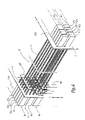
- FIG. 4 is a view in perspective of a part of the device of FIGS. 1 and 2 incorporating a plurality of modules such as that of FIG. 3 .
- FIG. 5 is a schematic view in perspective of a loom according to the invention, incorporating the device of FIGS. 1 to 4 .
- FIG. 6 is a view in perspective of a part of the loom of FIG. 5 .
- FIG. 7 is a view similar to FIG. 2 , for a device in accordance with a second form of embodiment of the invention.
- the electrical rotary actuator 1 shown in FIG. 1 is a servo-motor provided with a splined output shaft 11 of which X–X′ denotes the longitudinal geometric axis. This axis is parallel to the direction D of the weft yarns of the weaving loom.
- actuators 1 ′ In the vicinity of the actuator 1 there are disposed other actuators 1 ′ of the same type which are shown in dashed and dotted lines in FIG. 1 and of which the output shafts (not shown) are parallel to shaft 11 .
- each module 2 On the shaft 11 are mounted a plurality of identical modules 2 which each comprise a pinion 21 disposed around the shaft 11 and provided with a central opening allowing it to cooperate with the splines of this shaft in order to be driven in rotation about axis X–X′.
- the modules 2 may slide with reduced clearance on the corresponding shaft 11 .
- Each module 2 also comprises a rectilinear rack 22 substantially parallel to an axis Z–Z′ inclined with respect to the horizontal when the loom M is in normal configuration of use.
- Each module 2 also comprises a unitary casing 23 in which the pinion 21 is mounted to rotate freely, while the rack 22 may slide, in its longitudinal direction, in a groove 43 , made between a module 2 and an adjacent module 2 ′, and obturated by a finishing plate 44 .
- e denotes the distance along axis X–X′ between two adjacent modules 2 mounted on the shaft 11 .
- FIG. 1 shows that this distance is not necessarily constant.
- the modules 2 may be displaced parallel to axis X–X′, which makes it possible to vary the values of the distance e. It will also be understood that it is possible to add or to eliminate modules 2 on or from the shaft 11 .
- each rack 22 is fast with the upper end 24 a of a rod 24 made of epoxy carbon.
- the elements 22 and 24 may be glued or welded together, or fixed by any other appropriate means.
- the rod 24 is a semi-rigid element whose lower end 24 b is fixed to a heddle 3 provided with a mail 31 for passage of a warp yarn 4 .
- the rod 24 is adapted to exert, on the heddle 3 associated therewith, an upward effort of traction F 1 and a downward effort of thrust F′ 1 , with the result that the heddle 3 is controlled positively by the rod 24 without the need to use a return spring.
- the rod 24 may be made of other materials compatible with its function.
- it may be made of reinforced plastics material, steel or glass fibers.
- the loom M shown in FIG. 5 comprises a beam 101 and a reel 102 between which the warp yarns 4 of the loom circulate.
- D denotes the direction of the picks on the loom M, i.e. the direction of the weft yarns.
- the loom M also comprises a chassis 104 supporting the elements 101 and 102 and a system (not shown) for passage of the picks.
- the chassis 104 extends in a superstructure 105 disposed above the principal part of the loom M and supporting a shed forming device 110 and the perforated board 5 .
- This device is distributed in two units 110 A and 110 B mounted independently on the superstructure 105 .
- the unit 110 A is shown partially in FIG. 6 . It comprises two plates 111 and 112 between which is defined a volume V. On each plate 111 or 112 there are mounted electrical rotary actuators 1 whose output shafts 11 extend, through the plate 111 or 112 , in the volume V. For greater clarity of the drawing, only a part of the shafts 11 appears in FIG. 6 .
- the plates 111 and 112 and the actuators 1 are arranged in the superstructure 105 in such a manner that the shafts 11 , which are parallel to one another, are also substantially parallel to the direction D of the picks.
- the actuators 1 are arranged in rows and in columns on plates 111 and 112 .
- the plate 111 supports six rows of eight actuators 1 which form eight columns.
- the plate 112 bears five rows of actuators likewise forming eight columns.
- FIG. 6 only a part of the device has been shown and three rows R 1 to R 3 can be identified, of which five actuators are visible and form five columns C 1 to C 5 on the plate 111 , while two rows R 4 and R 5 of actuators forming five columns C′ 1 to C′ 5 are visible on plate 112 .
- the axis X–X′ is parallel to the direction D and perpendicular to an axis Y–Y′ along which rows R 1 to R 5 extend and to an axis Z–Z′ along which columns C 1 to C 5 and C′ 1 to C′ 5 extend.
- FIG. 5 only a few sheaths 25 have been shown between the units 110 A and 110 B, on the one hand, and the proximity of the zone of passage of the picks, on the other hand. This aims at simplifying the drawing. In practice, numerous sheaths 25 are used in place of a conventional harness and Jacquard loom.
- the different modules 2 intended to cooperate with the shafts 11 of the actuators 1 of row R 1 are integrated in a sub-assembly 40 shown in partially exploded perspective in FIG. 4 .
- This sub-assembly 40 extends substantially in a direction parallel to axis Y–Y′ and comprises eight modules 10 . It is formed by a one-piece casing 41 of plastics material constituting a plurality of unitary casings 23 and in which are formed housings 42 for receiving the pinions 21 and grooves 43 for slide of the racks 22 .
- the closure plate 44 of the sub-assembly 40 is shown removed in FIG. 4 . Openings 45 and 46 for passage of the shafts 11 are respectively provided in the casing 41 and in the plate 44 .
- the eight modules 20 intended to be driven by the actuators of row R 1 may be positioned on the corresponding shafts 11 , in groups, by manipulating the sub-assembly 40 . Positioning along the axis X–X′ of these different shafts may likewise be adjusted in groups, which represents a considerable saving of time when constructing the device 10 .
- each rod 24 is disposed inside a guiding sheath 25 which extends between a perforated board 5 and a comber board 6 respectively provided with orifices 5 a and 6 a for receiving and immobilizing the upper ( 25 a ) and lower ( 25 b ) ends of the sheaths 25 .
- the geometry of the sheaths 25 between the board 5 and the board 6 is variable and adapted to the desired weave.
- the distance d between two lower ends 25 b of sheath 25 , at the level of the board 6 is not necessarily equal to the distance d′ between two upper ends 25 a of sheath 25 , at the level of the board 5 , this distance d′ itself being substantially equal to the distance e between the modules 2 on the shaft 11 .
- the sheaths 25 corresponding to rods controlled by the same shaft 11 are preferably, but not necessarily, aligned at the level of the board 6 , as is seen in FIG. 1 .
- the ends 25 a and 25 b of the sheaths 25 are immobilized in the vicinity of the orifices 5 a and 6 a , the sheaths 25 being able to project above the board 5 and below the board 6 .
- each casing 23 there is provided a housing 23 a for receiving a first end 26 a of an elastic tongue 26 whose second end 26 b is free with respect to the casing 23 .
- This end 26 b is intended to be engaged in a longitudinal groove 22 b of a rack 22 of an adjacent module 2 .
- the groove 22 b extends towards the rack 22 opposite its toothing 22 c.
- the end 26 b of the tongue 26 may slide in the groove 22 b.
- the tongue 26 may come into abutment against a stop 22 d provided in the lower part of the groove 22 b, as shown in the left-hand side of FIG. 2 .
- the rack 22 is in top dead centre position, in the same way as the rod 24 and the heddle 3 associated therewith.
- This construction makes it possible to adjust at the same time the top dead centres of the different racks 22 driven by the same actuator 1 , insofar as it suffices to cause the corresponding shaft 11 to rotate until all the toothings 22 c of the racks escape the toothings 21 c of the pinions, while the racks are in abutment against the elastic tongues associated therewith.
- this tongue might be provided to cooperate with a stop (not shown) arranged in the vicinity of the upper part of the groove 22 b, this allowing the adjustment of the bottom dead centre of the stroke of the racks.
- the modules 52 comprise pinions 71 associated with racks 72 connected to harness cords 74 for controlling the heddles 53 .
- the harness cords 74 make it possible to exert an upward effort of traction F 1 on the heddles 53 , while the return springs 77 enable a downwardly directed effort to be exerted on these heddles.
- the springs 77 can allow a synchronisation of the different racks driven by the same shaft 61 , by performing a role similar to that of the tongues of the first embodiment.
- This second embodiment presents the particular advantage of being usable with a conventional Jacquard harness, a known perforated board and comber board.
- the invention has been represented with each effort transmission element 24 or 74 connected to a single heddle 3 or 53 . However, it is possible to control a plurality of heddles with such an element.
- the invention has been shown with the shafts 11 and 61 of the actuators 1 substantially parallel to direction D of the weft yarns. This is not obligatory, as it is possible to make use of the flexible nature of the effort transmission means 24 and 74 .
- an output shaft this is understood to mean any shaft driven by an actuator, whether it be in direct engagement therewith or through a reduction gear.
- the output shaft may be aligned or non-aligned with the geometric axis of the rotating part of the actuator, the possible reduction gear being able to perform the role of a bevel gear.
- the invention has been represented with pinions added on the output shafts of the actuators. It is also applicable with an actuator provided with an output shaft whose transverse section is such that it may engage directly with one or more racks, this shaft itself thus constituting one or more pinions within the meaning of the present invention. In other words, in the case of such a shaft meshing with a plurality of racks, it forms a succession of pinions attached to one another.
- the invention has been represented with actuators arranged above the heddles and the shed. However, it is applicable to the case of the actuators being placed below the heddles and the shed, which facilitates access to the shed and reduces space requirement.
Applications Claiming Priority (2)
| Application Number | Priority Date | Filing Date | Title |
|---|---|---|---|
| FR0108663A FR2826671B1 (fr) | 2001-06-29 | 2001-06-29 | Dispositif de formation de la foule sur un metier a tisser de type jacquard |
| PCT/FR2002/002267 WO2003002799A1 (fr) | 2001-06-29 | 2002-06-28 | Dispositif de formation de la foule sur un metier a tisser de type jacquard |
Publications (2)
| Publication Number | Publication Date |
|---|---|
| US20050103394A1 US20050103394A1 (en) | 2005-05-19 |
| US7007721B2 true US7007721B2 (en) | 2006-03-07 |
Family
ID=8864958
Family Applications (1)
| Application Number | Title | Priority Date | Filing Date |
|---|---|---|---|
| US10/481,795 Expired - Lifetime US7007721B2 (en) | 2001-06-29 | 2002-06-28 | Shedding device on a Jacquard-type weaving machine |
Country Status (10)
| Country | Link |
|---|---|
| US (1) | US7007721B2 (zh) |
| EP (1) | EP1399609B1 (zh) |
| JP (1) | JP4173441B2 (zh) |
| KR (1) | KR100840998B1 (zh) |
| CN (1) | CN100336953C (zh) |
| AT (1) | ATE431863T1 (zh) |
| DE (1) | DE60232410D1 (zh) |
| FR (1) | FR2826671B1 (zh) |
| TW (1) | TW567259B (zh) |
| WO (1) | WO2003002799A1 (zh) |
Cited By (6)
| Publication number | Priority date | Publication date | Assignee | Title |
|---|---|---|---|---|
| US20040159361A1 (en) * | 2003-01-16 | 2004-08-19 | Bram Vanderjeugt | Harness device for a weaving machine |
| US20140076453A1 (en) * | 2010-10-06 | 2014-03-20 | Ulster Carpet Mills (Holdings) Limited | Apparatus and method for loading tufts into a tuft carrier |
| US20150114511A1 (en) * | 2011-12-14 | 2015-04-30 | Snecma | Jacquard loom having optimized warp yarn density |
| US20160369430A1 (en) * | 2015-06-22 | 2016-12-22 | Staubli Lyon | Blade for moving hooks of a jacquard mechanism and jacquard mechanism comprising such a blade |
| CN111719213A (zh) * | 2020-06-04 | 2020-09-29 | 福建屹立智能化科技有限公司 | 一种单针控制提花模块、提花箱及地毯织机提花箱 |
| US11939707B2 (en) * | 2017-04-28 | 2024-03-26 | unspun, Inc. | Systems and methods for creating topographical woven fabric |
Families Citing this family (13)
| Publication number | Priority date | Publication date | Assignee | Title |
|---|---|---|---|---|
| BE1013193A3 (nl) * | 1999-12-23 | 2001-10-02 | Wiele Michel Van De Nv | Gaapvormingsinrichting voor een weefmachine. |
| KR100580234B1 (ko) * | 2004-04-19 | 2006-05-15 | 중소기업진흥공단 | 섬유강화 플라스틱을 이용한 저소음 직기용 프레임 |
| US7318456B2 (en) * | 2005-04-25 | 2008-01-15 | Massachusetts Institute Of Technology | Modular weaving system with individual yarn control |
| SE533266C2 (sv) * | 2008-12-16 | 2010-08-03 | Texo Ab | Vävmaskin med modulariserad drivning |
| FR2990958B1 (fr) * | 2012-05-24 | 2014-06-13 | Staubli Sa Ets | Dispositif de formation de la foule et metier a tisser equipe d'un tel dispositif |
| TWM493278U (zh) * | 2014-10-21 | 2015-01-11 | Deertex Inc | 具有透氣耐磨梭織鞋面之鞋類組件 |
| CN105350137B (zh) * | 2015-11-27 | 2017-05-10 | 江苏莱纳多智能装备有限公司 | 一种提花机开口行程放大装置 |
| CN105834877B (zh) * | 2016-04-25 | 2017-12-08 | 瑞安市日正汽车部件有限公司 | 一种工件可旋转且抛光轮位置可调的抛光机 |
| CN105904327B (zh) * | 2016-04-25 | 2017-11-21 | 扬州奥巴玛科技发展有限公司 | 一种可旋转工件且可收纳工件的抛光机 |
| CN105945703B (zh) * | 2016-04-25 | 2018-01-23 | 深圳磨霸智能科技有限公司 | 一种可对工件全面抛光的抛光机 |
| CN105922114B (zh) * | 2016-04-25 | 2018-04-20 | 中山超拓五金制品有限公司 | 一种抛光机 |
| CN105922108B (zh) * | 2016-04-25 | 2018-02-16 | 林家豪 | 一种可自动旋转工件的抛光机 |
| CN105773413B (zh) * | 2016-04-25 | 2017-11-28 | 扬州英奥车业有限公司 | 一种工件可旋转且设有工件收纳机构的抛光机 |
Citations (13)
| Publication number | Priority date | Publication date | Assignee | Title |
|---|---|---|---|---|
| US4627369A (en) * | 1983-06-27 | 1986-12-09 | Conrad Industries, Inc. | System for improving embroidered articles |
| EP0353005A1 (en) | 1988-07-26 | 1990-01-31 | Raymond Leslie Palmer | Loom or like control |
| US5140841A (en) * | 1986-12-31 | 1992-08-25 | Malimo Maschinenbau Gmbh | Control system for warp yarns |
| US5261464A (en) | 1991-09-24 | 1993-11-16 | Tecnotessile Centro Ricerche S.R.L. | Open eyelet heddle system for shedding warp threads |
| US5435353A (en) * | 1993-04-07 | 1995-07-25 | S.A. Des Etablissements Staubli (France) | Jacquard system with differentiated knife strokes to form an oblique shed |
| EP0668381A1 (en) | 1994-01-26 | 1995-08-23 | Danilo Jaksic | Jacquard machine |
| EP0750061A1 (fr) | 1995-06-20 | 1996-12-27 | Icbt Diederichs | Dispositif pour la réalisation d'une fausse lisière à pas de gaze sur une machine à tisser |
| US5743306A (en) * | 1994-05-12 | 1998-04-28 | Ulster Carpet Mills (Holdings) Limited | Apparatus and method for loading tufts into a tuft carrier |
| EP0848097A1 (de) | 1996-12-13 | 1998-06-17 | Schönherr Webstuhlbau GmbH | Antriebsvorrichtung für die Fachbildeelemente von Webmaschinen |
| JPH11350285A (ja) | 1998-06-08 | 1999-12-21 | Toyota Autom Loom Works Ltd | 織機の開口装置 |
| WO2000017431A1 (en) | 1998-09-18 | 2000-03-30 | Bonas Machine Company Limited | Motive drive for warp selection |
| US6092564A (en) | 1997-12-24 | 2000-07-25 | Bourgeaux; Pierre | Process and apparatus for mounting a funicular element in a jacquard electrical shed forming device |
| EP1069218A1 (fr) | 1999-05-31 | 2001-01-17 | Stäubli Faverges | Mécanique d'armure de type jacquard et métier à tisser équipé d'une telle mécanique |
Family Cites Families (1)
| Publication number | Priority date | Publication date | Assignee | Title |
|---|---|---|---|---|
| FR2794141B1 (fr) * | 1999-05-27 | 2001-07-13 | Staubli Gmbh | Dispositif de formation de la foule pour la realisation d'une lisiere et metier a tisser equipe d'un tel dispositif |
-
2001
- 2001-06-29 FR FR0108663A patent/FR2826671B1/fr not_active Expired - Fee Related
-
2002
- 2002-06-27 TW TW091114151A patent/TW567259B/zh not_active IP Right Cessation
- 2002-06-28 DE DE60232410T patent/DE60232410D1/de not_active Expired - Lifetime
- 2002-06-28 KR KR1020037017074A patent/KR100840998B1/ko active IP Right Grant
- 2002-06-28 WO PCT/FR2002/002267 patent/WO2003002799A1/fr active Application Filing
- 2002-06-28 CN CNB028126947A patent/CN100336953C/zh not_active Expired - Fee Related
- 2002-06-28 JP JP2003508758A patent/JP4173441B2/ja not_active Expired - Fee Related
- 2002-06-28 US US10/481,795 patent/US7007721B2/en not_active Expired - Lifetime
- 2002-06-28 EP EP02767535A patent/EP1399609B1/fr not_active Expired - Lifetime
- 2002-06-28 AT AT02767535T patent/ATE431863T1/de not_active IP Right Cessation
Patent Citations (14)
| Publication number | Priority date | Publication date | Assignee | Title |
|---|---|---|---|---|
| US4627369A (en) * | 1983-06-27 | 1986-12-09 | Conrad Industries, Inc. | System for improving embroidered articles |
| US5140841A (en) * | 1986-12-31 | 1992-08-25 | Malimo Maschinenbau Gmbh | Control system for warp yarns |
| EP0353005A1 (en) | 1988-07-26 | 1990-01-31 | Raymond Leslie Palmer | Loom or like control |
| US5261464A (en) | 1991-09-24 | 1993-11-16 | Tecnotessile Centro Ricerche S.R.L. | Open eyelet heddle system for shedding warp threads |
| US5435353A (en) * | 1993-04-07 | 1995-07-25 | S.A. Des Etablissements Staubli (France) | Jacquard system with differentiated knife strokes to form an oblique shed |
| EP0668381A1 (en) | 1994-01-26 | 1995-08-23 | Danilo Jaksic | Jacquard machine |
| US5743306A (en) * | 1994-05-12 | 1998-04-28 | Ulster Carpet Mills (Holdings) Limited | Apparatus and method for loading tufts into a tuft carrier |
| EP0750061A1 (fr) | 1995-06-20 | 1996-12-27 | Icbt Diederichs | Dispositif pour la réalisation d'une fausse lisière à pas de gaze sur une machine à tisser |
| EP0848097A1 (de) | 1996-12-13 | 1998-06-17 | Schönherr Webstuhlbau GmbH | Antriebsvorrichtung für die Fachbildeelemente von Webmaschinen |
| US6092564A (en) | 1997-12-24 | 2000-07-25 | Bourgeaux; Pierre | Process and apparatus for mounting a funicular element in a jacquard electrical shed forming device |
| JPH11350285A (ja) | 1998-06-08 | 1999-12-21 | Toyota Autom Loom Works Ltd | 織機の開口装置 |
| WO2000017431A1 (en) | 1998-09-18 | 2000-03-30 | Bonas Machine Company Limited | Motive drive for warp selection |
| EP1069218A1 (fr) | 1999-05-31 | 2001-01-17 | Stäubli Faverges | Mécanique d'armure de type jacquard et métier à tisser équipé d'une telle mécanique |
| US6216750B1 (en) | 1999-05-31 | 2001-04-17 | Staubli Faverges | Weaving loom panel support structure for jacquard selectors |
Cited By (10)
| Publication number | Priority date | Publication date | Assignee | Title |
|---|---|---|---|---|
| US20040159361A1 (en) * | 2003-01-16 | 2004-08-19 | Bram Vanderjeugt | Harness device for a weaving machine |
| US7168454B2 (en) * | 2003-01-16 | 2007-01-30 | N.V. Michel Van De Wiele | Harness device for a weaving machine |
| US20140076453A1 (en) * | 2010-10-06 | 2014-03-20 | Ulster Carpet Mills (Holdings) Limited | Apparatus and method for loading tufts into a tuft carrier |
| US8899275B2 (en) * | 2010-10-06 | 2014-12-02 | Ulster Carpet Mills (Holdings) Limited | Apparatus and method for loading tufts into a tuft carrier |
| US20150114511A1 (en) * | 2011-12-14 | 2015-04-30 | Snecma | Jacquard loom having optimized warp yarn density |
| US9200385B2 (en) * | 2011-12-14 | 2015-12-01 | Snecma | Jacquard loom having optimized warp yarn density |
| US20160369430A1 (en) * | 2015-06-22 | 2016-12-22 | Staubli Lyon | Blade for moving hooks of a jacquard mechanism and jacquard mechanism comprising such a blade |
| US9863068B2 (en) * | 2015-06-22 | 2018-01-09 | Staubli Lyon | Blade for moving hooks of a jacquard mechanism and jacquard mechanism comprising such a blade |
| US11939707B2 (en) * | 2017-04-28 | 2024-03-26 | unspun, Inc. | Systems and methods for creating topographical woven fabric |
| CN111719213A (zh) * | 2020-06-04 | 2020-09-29 | 福建屹立智能化科技有限公司 | 一种单针控制提花模块、提花箱及地毯织机提花箱 |
Also Published As
| Publication number | Publication date |
|---|---|
| TW567259B (en) | 2003-12-21 |
| ATE431863T1 (de) | 2009-06-15 |
| WO2003002799A1 (fr) | 2003-01-09 |
| EP1399609A1 (fr) | 2004-03-24 |
| KR20040012994A (ko) | 2004-02-11 |
| CN100336953C (zh) | 2007-09-12 |
| EP1399609B1 (fr) | 2009-05-20 |
| JP2004530812A (ja) | 2004-10-07 |
| FR2826671A1 (fr) | 2003-01-03 |
| DE60232410D1 (de) | 2009-07-02 |
| JP4173441B2 (ja) | 2008-10-29 |
| US20050103394A1 (en) | 2005-05-19 |
| CN1520475A (zh) | 2004-08-11 |
| FR2826671B1 (fr) | 2003-09-12 |
| KR100840998B1 (ko) | 2008-06-24 |
Similar Documents
| Publication | Publication Date | Title |
|---|---|---|
| US7007721B2 (en) | Shedding device on a Jacquard-type weaving machine | |
| US4936352A (en) | Double lift open shed jacquard machine | |
| GB2047755A (en) | Improvements in loom heald control means | |
| CN104233586A (zh) | 一种织机上用于控制纱罗织物经纱的装置及方法 | |
| BR9205639A (pt) | Processo para tecedura e cabeça de tear de tecedura | |
| US5927347A (en) | Modular shed-forming device for a jaquard loom | |
| US4031922A (en) | Vertically arranged triaxial weaving machine | |
| US5678612A (en) | Jacquard machine with plural lifter devices | |
| US6058983A (en) | Jacquard-type weaving mechanism and loom equipped with such a weaving mechanism | |
| US5462097A (en) | Piezoelectric devices for yarn control apparatus in a textile machine | |
| EP1783254B1 (en) | Warp yarn weaving device for selvedge formation in weaving looms | |
| US5363884A (en) | Selection bar design in an electronic warp selector | |
| ATE189489T1 (de) | Vorrichtung zum bilden einer dreherkante auf einer webmaschine | |
| US5511588A (en) | Electromagnetically activated jacquard machine with rotating lifting roll | |
| EP2929072B1 (en) | Module suitable for installation in a jacquard machine | |
| CN110512331B (zh) | 提花机以及设置提花机的方法 | |
| US7017617B2 (en) | Device for shed formation and Jacquard loom comprising same | |
| EP1396561B1 (en) | Shed forming device for a weaving machine | |
| US3410314A (en) | Control device for movable thread guides | |
| US5868173A (en) | Lifter device for a jacquard machine | |
| EP0860527B1 (en) | Electronically controlled warp selection system in looms | |
| CN109183236B (zh) | 一种织机选综系统 | |
| RU2177057C1 (ru) | Зевообразующее устройство ткацкого станка с волнообразно подвижным зевом | |
| US5711352A (en) | Mounting arrangement for linearly driven heald frames | |
| US3500872A (en) | Control device for movable thread guide |
Legal Events
| Date | Code | Title | Description |
|---|---|---|---|
| AS | Assignment |
Owner name: STAUBLI LYON, FRANCE Free format text: ASSIGNMENT OF ASSIGNORS INTEREST;ASSIGNORS:BASSI, DARIO;BOUCHET, DAMIEN;BOUTTE, GUILLAUME;REEL/FRAME:015349/0888 Effective date: 20031030 |
|
| FEPP | Fee payment procedure |
Free format text: PAYOR NUMBER ASSIGNED (ORIGINAL EVENT CODE: ASPN); ENTITY STATUS OF PATENT OWNER: LARGE ENTITY |
|
| STCF | Information on status: patent grant |
Free format text: PATENTED CASE |
|
| FPAY | Fee payment |
Year of fee payment: 4 |
|
| FPAY | Fee payment |
Year of fee payment: 8 |
|
| MAFP | Maintenance fee payment |
Free format text: PAYMENT OF MAINTENANCE FEE, 12TH YEAR, LARGE ENTITY (ORIGINAL EVENT CODE: M1553) Year of fee payment: 12 |