US7004656B2 - Stick-like paint container - Google Patents
Stick-like paint container Download PDFInfo
- Publication number
- US7004656B2 US7004656B2 US10/489,851 US48985104A US7004656B2 US 7004656 B2 US7004656 B2 US 7004656B2 US 48985104 A US48985104 A US 48985104A US 7004656 B2 US7004656 B2 US 7004656B2
- Authority
- US
- United States
- Prior art keywords
- stick
- inner container
- sleeve
- type cosmetic
- container
- Prior art date
- Legal status (The legal status is an assumption and is not a legal conclusion. Google has not performed a legal analysis and makes no representation as to the accuracy of the status listed.)
- Expired - Fee Related
Links
Images


Classifications
-
- A—HUMAN NECESSITIES
- A45—HAND OR TRAVELLING ARTICLES
- A45D—HAIRDRESSING OR SHAVING EQUIPMENT; EQUIPMENT FOR COSMETICS OR COSMETIC TREATMENTS, e.g. FOR MANICURING OR PEDICURING
- A45D40/00—Casings or accessories specially adapted for storing or handling solid or pasty toiletry or cosmetic substances, e.g. shaving soaps or lipsticks
- A45D40/06—Casings wherein movement of the lipstick or like solid is a screwing movement
-
- A—HUMAN NECESSITIES
- A45—HAND OR TRAVELLING ARTICLES
- A45D—HAIRDRESSING OR SHAVING EQUIPMENT; EQUIPMENT FOR COSMETICS OR COSMETIC TREATMENTS, e.g. FOR MANICURING OR PEDICURING
- A45D40/00—Casings or accessories specially adapted for storing or handling solid or pasty toiletry or cosmetic substances, e.g. shaving soaps or lipsticks
- A45D40/12—Casings with provision for preventing undesired movement of the stick
-
- A—HUMAN NECESSITIES
- A45—HAND OR TRAVELLING ARTICLES
- A45D—HAIRDRESSING OR SHAVING EQUIPMENT; EQUIPMENT FOR COSMETICS OR COSMETIC TREATMENTS, e.g. FOR MANICURING OR PEDICURING
- A45D40/00—Casings or accessories specially adapted for storing or handling solid or pasty toiletry or cosmetic substances, e.g. shaving soaps or lipsticks
- A45D40/16—Refill sticks; Moulding devices for producing sticks
Definitions
- the present invention relates to a container for a stick-type cosmetic. More particularly, the present invention relates to a container for a stick-type cosmetic which has a small number of components and can be easily disassembled and assembled.
- the stick-type cosmetic container is used by placing an internal structure having a function of allowing a stick-type cosmetic filled in an inner container to be projected and retracted in an outer cylinder or exterior container.
- a stick-type cosmetic container in which a stick-type cosmetic filled therein is projected and retracted by rotating an outer cylinder is widely used as a container for lipsticks and other cosmetics such as lip creams and concealers because of its ease of use.
- a conventional stick-type cosmetic container comprises a rotational cylinder 7 , sleeve 2 , inner container 5 filled with a stick-type cosmetic, outer cylinder 12 , and junction 13 , for example.
- the view on the right is a cross-sectional view substantially showing only the inner container 5 (the stick-type cosmetic is not shown), and the view on the left is a cross-sectional view showing a state in which the sleeve 2 , outer cylinder 12 , and junction 13 are removed.
- a small projection 6 is provided in the lower part of the outer surface of the inner container 5 , and an inner container guiding groove 4 is provided in the sleeve 2 .
- the screw 8 is threaded on the inner surface of the rotational cylinder 7 .
- the junction 13 plays a role in integrating the rotational cylinder 7 with the sleeve 2 .
- the outer cylinder 12 covers the rotational cylinder 7 encompassingly and is secured to the junction 13 by ultrasonic welding, bonding using an adhesive, or the like.
- the outer cylinder 12 is secured to the junction 13 and is integrated with the rotational cylinder 7 .
- the rotational cylinder 7 is also rotated.
- the small projection 6 in the inner container 5 is moved up and down along the inner container guiding groove 4 in the sleeve 2 according to the rotation of the screw 8 in the rotational cylinder 7 .
- the stick-type cosmetic is projected and retracted according to this movement.
- the small projection 6 in the inner container 5 is moved up and down along the inner container guiding groove 4 in the sleeve 2 according to the rotation of the rotational cylinder 7 .
- the inner container 5 finally drops out of the sleeve 2 . Therefore, movement of the small projection 6 in the inner container 5 must be limited within a certain range.
- the inner container 5 is prevented from dropping out by closing one end of the inner container guiding groove 4 , holding the opening of the inner container guiding groove 4 by the outer cylinder 12 from outside so that the inner container does not drop out, or not threading the screw 8 on the inner surface of the rotational cylinder 7 to the end.
- a conventional stick-type cosmetic container having the above configuration has no problem when the container is used as a disposable container.
- the container is highly inconvenient for use in terms of replacement of the inner container 5 , separate disposal of the metal and resin, and the like. Since the inner container 5 is configured not to drop out, the inner container 5 can be replaced by disassembly of the cosmetic container. However, the disassembly is practically impossible because the outer cylinder 12 is secured to the junction 13 .
- an object of the present invention is to provide a stick-type cosmetic container for which filling, disassembly, assembly, and separate disposal can be easily performed, and of which the inner container does not drop out during normal use.
- Another object of the present invention is to provide a stick-type cosmetic container comprising an internal structure of which the number of components is smaller than that of a conventional product and the members are commonly used for different types of products.
- the present inventors have conducted extensive studies to achieve the above objects. As a result, the inventors have found that refilling and replacement can be easily performed only for the inner container filled with a stick-type cosmetic, while the inner container can be prevented from dropping out during normal use, by improving the shape of the inner container guiding groove provided in the sleeve.
- the inventors have also found that it is not necessary to provide the junction for securing the inner container in order to prevent dropout used in a conventional stick-type cosmetic container, when a plurality of pawls are provided in the rotational cylinder and engaged with a rib provided on the outer surface approximately at the center of the sleeve.
- the present invention provides a stick-type cosmetic container comprising an internal structure that has a rotational cylinder, sleeve, and inner container into which a stick-like cosmetic can be filled, and that can project and retract the stick-type cosmetic filled into the inner container when a small projection provided in the inner container is guided by an inner container guiding groove provided in the sleeve and the small projection is moved up and down by a screw threaded on the inner surface of the rotational cylinder, wherein the inner container guiding groove provided in the sleeve in the internal structure comprises a linear primary groove, with the lower end being closed, and a secondary groove branched on the way of the primary groove and having an approximately inverted J shape, with the lower end being opened.
- the present invention also provides the stick-type cosmetic container further comprising a joining means provided in the rotational cylinder and the sleeve for rotatably joining the rotational cylinder and the sleeve, wherein the joining means comprises a plurality of pawls provided in the upper part of the rotational cylinder and a cyclic rib provided on the outer surface approximately at the center of the sleeve, the pawls being engaged with the cyclic rib to rotatably join the rotational cylinder and the sleeve.
- FIG. 1 is a drawing showing a configuration of a conventional stick-type cosmetic container.
- FIG. 2 is a drawing showing an example of an internal structure used in the stick-type cosmetic container of the present invention.
- the inner container is located in the uppermost part.
- FIG. 3 is a drawing showing the shape of a sleeve used in the internal structure as shown in FIG. 2 .
- FIG. 4 is a drawing showing the shape of a rotational cylinder used in the internal structure as shown in FIG. 2 .
- the view on the left is a front view
- the view at the center is a cross-sectional view
- the view on the right is a plan view.
- FIG. 5 is a drawing showing the shape of an inner container used in the internal structure as shown in FIG. 2 .
- the view on the left is a front view
- the view at the center is a right side view
- the view on the right is a plan view.
- FIG. 6 is a drawing showing the relation between an inner container guiding groove and a small projection provided in the inner container in the internal structure as shown in FIG. 2 .
- FIG. 7 is a drawing showing the relation between an inner container guiding groove and a small projection provided in an inner container in another example of the internal structure.
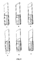
- FIG. 8 is a drawing showing movements of the members in the normal state (A-C) and movements of the members during replacement of the inner container (C-F) in the internal structure as shown in FIG. 2 .
- FIG. 9 is a drawing showing an example in which the small projection in the inner container used in the internal structure is provided with a resistive section.
- the view on the left is a front view
- the view on the right is a right side view
- the view on the lower left is a bottom view.
- FIG. 10 is a drawing showing another example of the small projection provided with the resistive section as shown in FIG. 9 , where a corner in the resistive section is cut off.
- the view on the left is a front view
- the view on the right is a right side view
- the view on the lower left is a bottom view.
- FIG. 2 is a drawing showing a configuration of an internal structure used in the stick-type cosmetic container of the present invention. (An exterior container is not shown.)
- the view on the right is a cross-sectional view substantially showing only the inner container, and the view on the left is a cross-sectional view showing a state in which a sleeve 2 is removed. (A stick-type cosmetic is not shown.)
- FIG. 2 is a drawing showing a configuration of an internal structure used in the stick-type cosmetic container of the present invention. (An exterior container is not shown.)
- the view on the right is a cross-sectional view substantially showing only the inner container
- the view on the left is a cross-sectional view showing a state in which a sleeve 2 is removed. (A stick-type cosmetic is not shown.)
- FIG. 2 is a drawing showing a configuration of an internal structure used in the stick-type cosmetic container of the present invention. (An exterior container is not shown.)
- the view on the right is
- 2 , 1 indicates an internal structure of the stick-type cosmetic container
- 2 indicates a sleeve
- 3 indicates a cyclic rib
- 4 indicates a inner container guiding groove
- 4 b indicates a secondary groove
- 5 indicates an inner container
- 6 indicates a small projection
- 7 indicates a rotational cylinder
- 8 indicates a screw
- 9 indicates a pawl
- 10 indicates a bottom lid.
- the stick-type cosmetic container of the present embodiment basically comprises a rotational cylinder 7 of which the inner surface is threaded by a screw 8 , a sleeve 2 , and an inner container 5 filled with a stick-type cosmetic.
- the shape of an inner container guiding groove 4 provided in the sleeve 2 significantly differs from the shape of the inner container guiding groove 4 of a conventional stick-type cosmetic container.
- the shape of the sleeve 2 used in the present embodiment is shown in FIG. 3 .
- the inner container guiding groove 4 of the sleeve 2 branches into a primary groove and a secondary groove 4 b at the lower end.
- the shape of the secondary groove 4 b (including the lowermost part of the primary groove) is an approximately inverted J shape.
- the secondary groove 4 b is opened downward.
- the sleeve 2 differs from the sleeve 2 of a conventional stick-type cosmetic container.
- the rotational cylinder 7 differs from a conventional rotational cylinder 7 in that a plurality of pawls 9 are provided in the upper part and that the screw 8 is threaded to the end in the downward direction (opened) but is not threaded to the end in the upward direction (closed).
- the pawls 9 in the rotational cylinder 7 preferably have concave portions on the inner surface.
- the inner container 5 used in combination with the sleeve 2 is a cylinder of which the lower part has a small projection 6 .
- the upper and lower parts of the inner container 5 are opened.
- the inner surface of the inner container 5 may be optionally provided with a dropout-preventing projection (not shown) to prevent the filled stick-type cosmetic from dropping out of the inner container 5 .
- the small projection 6 may have any shape inasmuch as the projection 6 can be moved in the inner container guiding groove 4 by the rotational force of the screw 8 .
- the shape is preferably cylindrical or hemispheric, generally.
- the outer surface of the inner container 5 may be optionally provided with a suppressing section 15 to reduce the space between the inner container 5 and the sleeve 2 and suppress rattling. Any shape may be employed for the suppressing section 15 without specific limitations insofar as rattling of the inner container 5 and the sleeve 2 can be suppressed.
- One of the features of the present invention is that disassembly, assembly, and replacement of the inner container 5 can be easily performed, while the inner container 5 filled with a stick-type cosmetic does not drop out during normal use.
- the mechanism possessing this feature will be described with reference to FIGS. 6 and 8 .
- the small projection 6 When the small projection 6 reaches the entrance of the secondary groove 4 b (the position indicated as the black circle in FIG. 6 ), since there is no guiding groove on the left, the projection 6 is moved further to the left. However, since the force of causing this leftward movement is a force in the direction perpendicular to the gradient of the screw 8 , the small projection 6 hits a small projection support 11 provided according to the gradient of the screw 8 and is returned to the primary groove. The small projection 6 is then moved down and stored in a primary groove lowermost part 14 (C in FIG. 8 ). Since the bottom of the primary groove is closed, the small projection 6 cannot be moved further downward. The inner container 5 stops accordingly. Here, a force in the axial direction is not applied to the rotational cylinder 7 .
- the inner container 5 can be moved up and down in the sleeve 2 without dropping out downward.
- a mechanism similar to the mechanism using the inner container guiding groove 4 shown in FIG. 6 can also be realized by utilizing the groove 4 shown in FIG. 7 .
- the secondary groove 4 b is provided on the side opposite to the side of the inner container guiding groove 4 in FIG. 6 .
- the small projection 6 in the inner container 5 is moved along the left side of the inner container guiding groove 4 and directly reaches the primary groove lowermost part 14 .
- the small projection 6 hits the small projection support 11 provided corresponding to this force direction. The projection 6 is then returned to the primary groove and continues moving up.
- the small projection 6 can be moved up and down within a certain range, while the inner container 5 is not detached from the inner container guiding groove 4 , even if the inner container guiding groove 4 is provided with the secondary groove 4 b.
- the small projection 6 does not intrude into the secondary groove 4 b during normal use.
- the small projection 6 when the small projection 6 is near the entrance of the secondary groove 4 b (the part corresponding to 4 c in FIG. 7 , hereinafter the same), if a force is applied from outside, for example, if the stick-type cosmetic is dropped or if reaction to the force for using the cosmetic occurs in the direction to the secondary groove 4 b , the small projection 6 may accidentally intrude into the secondary groove 4 b .
- the small projection 6 can be prevented from accidentally intruding into the secondary groove 4 b by providing the small projection 6 with a resistive section 16 as shown in FIG. 9 .
- FIG. 10 shows an example of the small projection 6 in which the side of the corner 17 (left side in FIG. 10 ) contacting the secondary groove 4 b in the inner container guiding groove 4 as shown in FIG. 7 is cut off.
- the bottom lid or bottom sticker (not shown) of the stick-type cosmetic is removed if present to make the inner container 5 visible.
- the small projection 6 is moved so that the inner container 5 can be moved down, followed by storing the small projection 6 in the lowermost part 14 of the inner container guiding groove 4 a (C in FIG. 8 ).
- the small projection 7 is moved to the entrance to the secondary groove 4 b by rotating the rotational cylinder 7 to the right (D in FIG. 8 ; rotated about 30° from the position of C).
- the small projection 6 is moved in the leftward direction by an appropriate means such as a jig, followed by rotating the rotational cylinder 7 to the left (E in FIG. 8 ).
- the inner container 5 is thus ejected downward via the secondary groove 4 b opened downward (F in FIG. 8 ).
- Installation of a new inner container 5 as component replacement is carried out by inserting the container 5 from the bottom of an internal structure 1 . This insertion is performed by mating the thread on the secondary groove 4 b , letting the small projection 6 in the inner container 5 into this section, and then rotating the rotational cylinder 7 to the right. Since a force in the upper rightward direction is applied to the small projection 6 in the secondary groove 4 b by the screw 8 in the rotational cylinder 7 , the projection 6 can enter the primary groove of the inner container guiding groove 4 via the secondary groove 4 b.
- Another feature of the present invention is that an outer cylinder 12 and a junction 13 that have been necessary in a conventional manner are not required.
- This feature is realized by a means by which the rotational cylinder 7 and the sleeve 2 can be rotatably joined.
- a plurality of the pawls 9 is provided in the upper part of the rotational cylinder 7
- a cyclic rib 3 is provided approximately at the center of the outer surface of the sleeve 2 .
- the pawls 9 are engaged with the cyclic rib 3 to rotatably join the rotational cylinder 7 and the sleeve 2 .
- a conventional stick-type cosmetic container comprises the rotational cylinder 7 , sleeve 2 , inner container 5 , outer cylinder 12 , and junction 13 .
- the rotational cylinder 7 and the outer cylinder 12 are joined via the junction 13 .
- the rotational cylinder 7 is rotated by rotating the outer cylinder 12 so that the stick-type container filled in the inner container 5 is let out.
- the pawls 9 in the rotational cylinder 7 are engaged with the cyclic rib 3 in the sleeve 2 to rotatably join the rotational cylinder 7 and the sleeve 2 in the present invention, as described above. Therefore, the inner container 5 can be moved up and down by the rotation involving the two members.
- the stick-type cosmetic container of the present invention comprises the internal structure 1 having the rotational cylinder 7 , the sleeve 2 , and the inner container 5 .
- the internal structure 1 is detachably attached to the exterior outer cylinder 12 to form a container.
- Various designs can be made for the outer cylinder 12 .
- the rotational cylinder 7 is colored, designed, or attached to a lid having a shape corresponding to the cylinder 7
- the internal structure 1 can be a stick-type cosmetic container having a small number of components.
- the internal structure 1 can thereby be commonly used for various types of stick-type cosmetic containers. Filling, disassembly, and replacement of the inner container 5 can be carried out for the internal structure 1 .
- the internal structure 1 is detachably incorporated in the outer cylinder 12 or an exterior container including the cylinder 12 , separate disposal after use is possible.
- the stick-type cosmetic container of the present invention as a conventional stick-type cosmetic container by securing the outer cylinder 12 to the rotational cylinder 7 by any means and attaching a necessary lid.
- the following method can be given.
- the rotational cylinder 7 is rotated to the right with respect to the sleeve 2 so that the small projection 6 in the inner container 5 is moved from the secondary groove 4 b to the primary groove of the inner container guiding groove 4 .
- the internal structure 1 is thus formed.
- the internal structure 1 is incorporated in the outer cylinder 12 or an exterior container including the cylinder 12 to provide a stick-type cosmetic container.
- the stick-type cosmetic container of the present invention is filled with a cosmetic in the following manner.
- the stick-type cosmetic is retained by adhesion to the inner container 5 or an escape-preventing projection in the inner container 5 , for example.
- a small clearance is provided by separation of the cosmetic from the sleeve 2 due to reduction in volume by solidification. Therefore, the cosmetic can be moved up and down by rotating the rotational cylinder 7 when the cap is removed.
- the primary groove lowermost part 14 in FIG. 7 plays a role in separating a part of the stick-type cosmetic that remains not separated from the inner surface of the sleeve 2 even after the cosmetic is filled and solidified, by causing the inner container 5 to be moved slightly in the upper perpendicular direction before the small projection 6 reaches the entrance of the secondary groove 4 b .
- a force in the rotational direction is applied to the stick-type cosmetic during separation, a force in the crosswise direction to push the stick-type cosmetic toward the sleeve 2 is generated.
- the stick-type cosmetic and the inner surface of the sleeve 2 are in contact in a large surface area and are rubbed together.
- the primary groove lowermost part 14 has a linear shape as shown in FIG. 7 , the initial movement of the small projection 6 and the stick-type cosmetic in the inner container 5 is a upward linear movement and does not include a rotational movement. Therefore, the stick-type cosmetic can be separated from the part of the inner surface of the sleeve 2 to which the cosmetic is attached without breaks or cracks.
- the length t of the primary groove lowermost part 14 is not specifically limited. However, the length t is preferably 0.3–1.5 mm, and particularly preferably 0.5–1 mm, in terms of attachment or detachment of the inner container 5 , for example.
- the bottom In the internal structure 1 of the stick-type cosmetic container of the present invention, the bottom must be opened, since filling is performed from the bottom and the internal structure 1 is installed from the bottom of the outer cylinder 12 .
- the product in this state does not have good appearance.
- a bottom lid 10 or a sticker may be attached to the bottom. It is convenient for buying a stick-type cosmetic for replacement if the product number, color tone, or the like is described on a sticker to be attached to the bottom or the bottom lid 10 .
- the internal structure 1 in the stick-type cosmetic container of the present invention as described above can be formed basicly as a stick-type cosmetic container of which the material, size, shape, and the like are almost the same as those of a stick-type cosmetic container that has been conventionally provided.
- the container of the present invention differs in some respects such as the shape of the sleeve 2 , the shape of the upper part of the rotational cylinder 7 , and the fact that the screw 8 on the inner surface of the rotational cylinder 7 is threaded to the end in the present invention.
- the top of the inner container 5 does not necessarily have a spired shape. Any other shape is possible.
- Various metals and plastics can be used as a material for the sleeve 2 , rotational cylinder 7 , or inner container 5 , as in the case of conventional products.
- other shape-retaining materials such as papers and ceramics may be used. This applies to a material for the outer cylinder 12 or an exterior container including the cylinder 12 .
- a feature of the stick-type cosmetic container of the present invention is that the inner container does not drop out during normal use and that disassembly and replacement of the members can be easily carried out using a simple jig or the like when the stick-type cosmetic is used up.
- the number of members forming the container can be reduced.
- the materials used can also be rationalized by standardizing the members.
- the stick-type cosmetic container of the present invention as a product that can save resources and be recycled can be advantageously used for cosmetics such as lipsticks, lip creams, concealers, skin-whitening sticks, and sunburn-preventive sticks.
Landscapes
- Containers And Packaging Bodies Having A Special Means To Remove Contents (AREA)
- Cosmetics (AREA)
- Coating Apparatus (AREA)
- Tubes (AREA)
Applications Claiming Priority (3)
| Application Number | Priority Date | Filing Date | Title |
|---|---|---|---|
| JP2001299676 | 2001-09-28 | ||
| JP2001-299676 | 2001-09-28 | ||
| PCT/JP2002/009935 WO2003028502A1 (fr) | 2001-09-28 | 2002-09-26 | Reservoir de peinture de type en baton |
Publications (2)
| Publication Number | Publication Date |
|---|---|
| US20040265033A1 US20040265033A1 (en) | 2004-12-30 |
| US7004656B2 true US7004656B2 (en) | 2006-02-28 |
Family
ID=19120390
Family Applications (1)
| Application Number | Title | Priority Date | Filing Date |
|---|---|---|---|
| US10/489,851 Expired - Fee Related US7004656B2 (en) | 2001-09-28 | 2002-09-26 | Stick-like paint container |
Country Status (11)
| Country | Link |
|---|---|
| US (1) | US7004656B2 (ko) |
| EP (1) | EP1430807B1 (ko) |
| JP (1) | JP4283676B2 (ko) |
| KR (1) | KR100902274B1 (ko) |
| CN (1) | CN1250134C (ko) |
| AT (1) | ATE467364T1 (ko) |
| CA (1) | CA2461589C (ko) |
| DE (1) | DE60236363D1 (ko) |
| HK (1) | HK1071040A1 (ko) |
| TW (1) | TWI222852B (ko) |
| WO (1) | WO2003028502A1 (ko) |
Cited By (3)
| Publication number | Priority date | Publication date | Assignee | Title |
|---|---|---|---|---|
| US20050260025A1 (en) * | 2002-07-29 | 2005-11-24 | Kose Corporation | Stick-type cosmetic paint container |
| US20190110569A1 (en) * | 2015-05-26 | 2019-04-18 | L'oreal | Device for treating the hair having push-release cartridge locking |
| US20220312937A1 (en) * | 2021-04-05 | 2022-10-06 | Tokiwa Corporation | Feeding container |
Families Citing this family (13)
| Publication number | Priority date | Publication date | Assignee | Title |
|---|---|---|---|---|
| KR100902274B1 (ko) | 2001-09-28 | 2009-06-10 | 가부시키가이샤 코세 | 스틱 형상 화장품용 용기 |
| JP5932420B2 (ja) * | 2012-03-21 | 2016-06-08 | 株式会社ヒダン | カートリッジ式棒状化粧料収容容器 |
| JP6706021B2 (ja) * | 2015-08-07 | 2020-06-03 | 竹内工業株式会社 | 棒状化粧品収納容器 |
| FR3047155A1 (fr) * | 2016-01-29 | 2017-08-04 | Chanel Parfums Beaute | Article de cosmetique notamment pour les levres comprenant une grille |
| JP6744725B2 (ja) * | 2016-02-05 | 2020-08-19 | 株式会社コーセー | 棒状化粧品容器の抜け防止構造 |
| KR101643119B1 (ko) | 2016-03-30 | 2016-07-26 | 김진우 | 나선 구조를 갖는 스틱 타입 화장품 용기 |
| KR200487201Y1 (ko) * | 2017-07-10 | 2018-08-20 | 소준 | 양방향 선스틱 용기 |
| WO2019142847A1 (ja) * | 2018-01-19 | 2019-07-25 | 株式会社コーセー | 棒状化粧料収納容器 |
| CN110169644A (zh) * | 2019-05-25 | 2019-08-27 | 天津竹内装璜有限公司 | 一种化妆品收纳容器的中束装置 |
| FR3104922B1 (fr) * | 2019-12-20 | 2024-04-26 | Albea Services | Distributeur de bâtonnet cosmétique, notamment rouges à lèvres, avec indicateur d’usage |
| CN111708104B (zh) * | 2020-07-16 | 2021-07-13 | 石家庄铁道大学 | 不同高度雪通量及积雪密度测量装置 |
| KR102423782B1 (ko) | 2020-08-18 | 2022-07-22 | 임성민 | 스틱형 화장품 용기 |
| DE202021103673U1 (de) * | 2021-07-08 | 2021-07-16 | Holy Pit Gmbh | Nachfüllbarer Körperpflege- oder Kosmetik-Stick |
Citations (8)
| Publication number | Priority date | Publication date | Assignee | Title |
|---|---|---|---|---|
| US3547551A (en) * | 1966-09-22 | 1970-12-15 | Ejectoret Sa | Holders for protecting sticks of pasty materials |
| EP0379607A1 (en) | 1987-07-31 | 1990-08-01 | Yoshino Kogyosho Co., Ltd. | Cosmetic casing capable of protruding cosmetic material |
| US5746530A (en) * | 1994-03-01 | 1998-05-05 | Oota; Etsuji | Medium container and its spare medium |
| US5873379A (en) * | 1998-05-04 | 1999-02-23 | Color Access, Inc. | Mass retention device with bellows |
| US5899621A (en) * | 1998-02-18 | 1999-05-04 | Der Kwei Cosmetic Packaging Co., Limited | Lipstick swivel mechanism with brake function |
| US5988917A (en) | 1998-10-15 | 1999-11-23 | Charles Chang | Cosmetic stick dispenser |
| JP2002223847A (ja) | 2001-02-01 | 2002-08-13 | Kose Corp | スティック状化粧料用容器 |
| US20040265033A1 (en) | 2001-09-28 | 2004-12-30 | Mitsuru Kurihara | Stick-like paint container |
Family Cites Families (2)
| Publication number | Priority date | Publication date | Assignee | Title |
|---|---|---|---|---|
| JP3522826B2 (ja) * | 1994-05-16 | 2004-04-26 | 株式会社ナリス化粧品 | 繰上式棒状化粧料容器 |
| JP3771065B2 (ja) * | 1998-10-28 | 2006-04-26 | 株式会社吉野工業所 | 棒状化粧料繰出し容器 |
-
2002
- 2002-09-26 KR KR1020047004390A patent/KR100902274B1/ko active IP Right Grant
- 2002-09-26 AT AT02772926T patent/ATE467364T1/de not_active IP Right Cessation
- 2002-09-26 DE DE60236363T patent/DE60236363D1/de not_active Expired - Lifetime
- 2002-09-26 EP EP02772926A patent/EP1430807B1/en not_active Expired - Lifetime
- 2002-09-26 JP JP2003531849A patent/JP4283676B2/ja not_active Expired - Fee Related
- 2002-09-26 CA CA002461589A patent/CA2461589C/en not_active Expired - Fee Related
- 2002-09-26 TW TW091122215A patent/TWI222852B/zh not_active IP Right Cessation
- 2002-09-26 CN CNB028189485A patent/CN1250134C/zh not_active Expired - Lifetime
- 2002-09-26 US US10/489,851 patent/US7004656B2/en not_active Expired - Fee Related
- 2002-09-26 WO PCT/JP2002/009935 patent/WO2003028502A1/ja active IP Right Grant
-
2005
- 2005-05-06 HK HK05103832A patent/HK1071040A1/xx not_active IP Right Cessation
Patent Citations (8)
| Publication number | Priority date | Publication date | Assignee | Title |
|---|---|---|---|---|
| US3547551A (en) * | 1966-09-22 | 1970-12-15 | Ejectoret Sa | Holders for protecting sticks of pasty materials |
| EP0379607A1 (en) | 1987-07-31 | 1990-08-01 | Yoshino Kogyosho Co., Ltd. | Cosmetic casing capable of protruding cosmetic material |
| US5746530A (en) * | 1994-03-01 | 1998-05-05 | Oota; Etsuji | Medium container and its spare medium |
| US5899621A (en) * | 1998-02-18 | 1999-05-04 | Der Kwei Cosmetic Packaging Co., Limited | Lipstick swivel mechanism with brake function |
| US5873379A (en) * | 1998-05-04 | 1999-02-23 | Color Access, Inc. | Mass retention device with bellows |
| US5988917A (en) | 1998-10-15 | 1999-11-23 | Charles Chang | Cosmetic stick dispenser |
| JP2002223847A (ja) | 2001-02-01 | 2002-08-13 | Kose Corp | スティック状化粧料用容器 |
| US20040265033A1 (en) | 2001-09-28 | 2004-12-30 | Mitsuru Kurihara | Stick-like paint container |
Non-Patent Citations (1)
| Title |
|---|
| U.S. Appl. No. 10/522,376, filed Jan. 26, 2005, inventor Kurihara et al. |
Cited By (6)
| Publication number | Priority date | Publication date | Assignee | Title |
|---|---|---|---|---|
| US20050260025A1 (en) * | 2002-07-29 | 2005-11-24 | Kose Corporation | Stick-type cosmetic paint container |
| US7422387B2 (en) * | 2002-07-29 | 2008-09-09 | Kose Corporation | Stick-type cosmetic paint container |
| US20190110569A1 (en) * | 2015-05-26 | 2019-04-18 | L'oreal | Device for treating the hair having push-release cartridge locking |
| US11399609B2 (en) * | 2015-05-26 | 2022-08-02 | L'oreal | Device for treating the hair having push-release cartridge locking |
| US20220312937A1 (en) * | 2021-04-05 | 2022-10-06 | Tokiwa Corporation | Feeding container |
| US11896112B2 (en) * | 2021-04-05 | 2024-02-13 | Tokiwa Corporation | Feeding container |
Also Published As
| Publication number | Publication date |
|---|---|
| WO2003028502A1 (fr) | 2003-04-10 |
| JP4283676B2 (ja) | 2009-06-24 |
| CN1250134C (zh) | 2006-04-12 |
| KR100902274B1 (ko) | 2009-06-10 |
| CA2461589C (en) | 2010-01-12 |
| CA2461589A1 (en) | 2003-04-10 |
| DE60236363D1 (de) | 2010-06-24 |
| EP1430807A4 (en) | 2004-12-29 |
| US20040265033A1 (en) | 2004-12-30 |
| HK1071040A1 (en) | 2005-07-08 |
| EP1430807B1 (en) | 2010-05-12 |
| JPWO2003028502A1 (ja) | 2005-01-13 |
| CN1558730A (zh) | 2004-12-29 |
| EP1430807A1 (en) | 2004-06-23 |
| TWI222852B (en) | 2004-11-01 |
| KR20040047859A (ko) | 2004-06-05 |
| ATE467364T1 (de) | 2010-05-15 |
Similar Documents
| Publication | Publication Date | Title |
|---|---|---|
| US7004656B2 (en) | Stick-like paint container | |
| JP4391936B2 (ja) | スティック状化粧料用容器 | |
| US8132977B2 (en) | Refill container for consumer products | |
| US5255990A (en) | Reset elevator/threaded shaft dispensing package for stick form product and a refill cartridge therefor | |
| EP4342330A1 (en) | Compact container having refill container replacement structure | |
| US6174099B1 (en) | Device for applying liquid cosmetic products | |
| CN110278708B (zh) | 容器盖及具有盖的包装 | |
| JP3202178B2 (ja) | 化粧料塗布容器 | |
| US6405737B1 (en) | Lipstick package with dispensing compartment(s) | |
| CN113520021A (zh) | 用于涂敷化妆品的容器的机构和包括这种机构的容器 | |
| KR20170062249A (ko) | 파우더 용기 | |
| JP2000041733A (ja) | カートリッジ式棒状化粧材繰出容器 | |
| JP2000201729A (ja) | 液体化粧料の収納容器 | |
| KR101091881B1 (ko) | 분말용 화장품케이스 | |
| KR200217591Y1 (ko) | 화장품 용기 | |
| KR100429714B1 (ko) | 립스틱 용기 | |
| JP4301355B2 (ja) | 棒状化粧品繰り出し容器 | |
| JP4030159B2 (ja) | 液体化粧料の収納容器 | |
| JP4273482B2 (ja) | 棒状化粧品繰り出し容器 | |
| KR200140860Y1 (ko) | 휴대용 화장품 케이스 | |
| JP2004049260A (ja) | 固形化粧品の繰出容器 | |
| KR200356308Y1 (ko) | 화장품 케이스 | |
| KR20230046159A (ko) | 화장품 용기 | |
| JPH046656Y2 (ko) | ||
| JPH09308525A (ja) | 化粧料等の収納容器 |
Legal Events
| Date | Code | Title | Description |
|---|---|---|---|
| AS | Assignment |
Owner name: KOSE CORPORATION, JAPAN Free format text: ASSIGNMENT OF ASSIGNORS INTEREST;ASSIGNORS:KURIHARA, MITSURU;NAKAMURA, MITSUNOBU;IWASAKI, KAZUTSUGU;AND OTHERS;REEL/FRAME:015909/0500 Effective date: 20040220 |
|
| CC | Certificate of correction | ||
| FPAY | Fee payment |
Year of fee payment: 4 |
|
| FPAY | Fee payment |
Year of fee payment: 8 |
|
| FEPP | Fee payment procedure |
Free format text: MAINTENANCE FEE REMINDER MAILED (ORIGINAL EVENT CODE: REM.) |
|
| LAPS | Lapse for failure to pay maintenance fees |
Free format text: PATENT EXPIRED FOR FAILURE TO PAY MAINTENANCE FEES (ORIGINAL EVENT CODE: EXP.) |
|
| STCH | Information on status: patent discontinuation |
Free format text: PATENT EXPIRED DUE TO NONPAYMENT OF MAINTENANCE FEES UNDER 37 CFR 1.362 |
|
| FP | Lapsed due to failure to pay maintenance fee |
Effective date: 20180228 |