US6934704B2 - Automatic manhour setting system and method, distributed client/server system, and computer program storage medium - Google Patents
Automatic manhour setting system and method, distributed client/server system, and computer program storage medium Download PDFInfo
- Publication number
- US6934704B2 US6934704B2 US09/753,726 US75372601A US6934704B2 US 6934704 B2 US6934704 B2 US 6934704B2 US 75372601 A US75372601 A US 75372601A US 6934704 B2 US6934704 B2 US 6934704B2
- Authority
- US
- United States
- Prior art keywords
- work
- standard
- manhour
- database
- data
- Prior art date
- Legal status (The legal status is an assumption and is not a legal conclusion. Google has not performed a legal analysis and makes no representation as to the accuracy of the status listed.)
- Expired - Fee Related, expires
Links
Images


Classifications
-
- G—PHYSICS
- G06—COMPUTING; CALCULATING OR COUNTING
- G06Q—INFORMATION AND COMMUNICATION TECHNOLOGY [ICT] SPECIALLY ADAPTED FOR ADMINISTRATIVE, COMMERCIAL, FINANCIAL, MANAGERIAL OR SUPERVISORY PURPOSES; SYSTEMS OR METHODS SPECIALLY ADAPTED FOR ADMINISTRATIVE, COMMERCIAL, FINANCIAL, MANAGERIAL OR SUPERVISORY PURPOSES, NOT OTHERWISE PROVIDED FOR
- G06Q10/00—Administration; Management
- G06Q10/06—Resources, workflows, human or project management; Enterprise or organisation planning; Enterprise or organisation modelling
- G06Q10/063—Operations research, analysis or management
- G06Q10/0639—Performance analysis of employees; Performance analysis of enterprise or organisation operations
-
- Y—GENERAL TAGGING OF NEW TECHNOLOGICAL DEVELOPMENTS; GENERAL TAGGING OF CROSS-SECTIONAL TECHNOLOGIES SPANNING OVER SEVERAL SECTIONS OF THE IPC; TECHNICAL SUBJECTS COVERED BY FORMER USPC CROSS-REFERENCE ART COLLECTIONS [XRACs] AND DIGESTS
- Y10—TECHNICAL SUBJECTS COVERED BY FORMER USPC
- Y10S—TECHNICAL SUBJECTS COVERED BY FORMER USPC CROSS-REFERENCE ART COLLECTIONS [XRACs] AND DIGESTS
- Y10S707/00—Data processing: database and file management or data structures
- Y10S707/912—Applications of a database
- Y10S707/913—Multimedia
- Y10S707/915—Image
-
- Y—GENERAL TAGGING OF NEW TECHNOLOGICAL DEVELOPMENTS; GENERAL TAGGING OF CROSS-SECTIONAL TECHNOLOGIES SPANNING OVER SEVERAL SECTIONS OF THE IPC; TECHNICAL SUBJECTS COVERED BY FORMER USPC CROSS-REFERENCE ART COLLECTIONS [XRACs] AND DIGESTS
- Y10—TECHNICAL SUBJECTS COVERED BY FORMER USPC
- Y10S—TECHNICAL SUBJECTS COVERED BY FORMER USPC CROSS-REFERENCE ART COLLECTIONS [XRACs] AND DIGESTS
- Y10S707/00—Data processing: database and file management or data structures
- Y10S707/953—Organization of data
- Y10S707/955—Object-oriented
-
- Y—GENERAL TAGGING OF NEW TECHNOLOGICAL DEVELOPMENTS; GENERAL TAGGING OF CROSS-SECTIONAL TECHNOLOGIES SPANNING OVER SEVERAL SECTIONS OF THE IPC; TECHNICAL SUBJECTS COVERED BY FORMER USPC CROSS-REFERENCE ART COLLECTIONS [XRACs] AND DIGESTS
- Y10—TECHNICAL SUBJECTS COVERED BY FORMER USPC
- Y10S—TECHNICAL SUBJECTS COVERED BY FORMER USPC CROSS-REFERENCE ART COLLECTIONS [XRACs] AND DIGESTS
- Y10S707/00—Data processing: database and file management or data structures
- Y10S707/99931—Database or file accessing
- Y10S707/99933—Query processing, i.e. searching
- Y10S707/99936—Pattern matching access
Definitions
- the present invention relates to an automatic manhour setting method and system for automatically setting manhours for an enormous number of work standards representing works in, e.g., an assembly workshop, a distributed client/server system, and a computer program storage medium.
- the present invention has been made to solve the above problem, and has as its object to propose automatic manhour setting system and method capable of automatically giving manhours to an enormous number of work standards, a distributed client/server system, and a computer program storage medium.
- an automatic manhour setting system is characterized by having the following arrangement.
- an automatic manhour setting system for giving manhour data to work standard data converted into computer data, characterized by comprising:
- a standard manhour database ( 2805 ) designed to be readable, in which a number of pairs each constituted by a work standard described by a standardized standard expression and a manhour corresponding to the work standard are registered in advance;
- setting means for, for each of target work standards to which manhours are to be given, matching an expression of the target work standard with the standard expressions of the work standards in the standard manhour database and setting a standard manhour of a matching work standard in the database as a manhour of the target work standard;
- manhour file means for storing a set manhour file.
- the target work standard to which the manhour is to be given is described by an operation phrase representing an operation of a work, an object phrase representing a target of the operation, and a comment phrase representing auxiliary information related to the operation and/or object, and each of the work standards in the database is also described by an operation phrase, object phrase, and comment phrase. This is because a work is most simply and exactly expressed by an operation phrase, object phrase, and comment phrase.
- a first comment related to an object of an operation for the target work standard to which the manhour is to be given, a first comment related to an object of an operation, an object phrase representing the object of the operation, a second comment related to the operation, and an operation phrase representing the operation of the work are described in a predetermined order, and for each of the work standards in the database, a first comment, object phrase, second comment, and operation phrase are also described in the predetermined order.
- search based on complete matching between the expression of the target work standard and the standard expression of the work standard in the standard manhour database is preferentially executed.
- search based on complete matching is not always successful.
- search based on partial matching is preferably used for the target work standard for which the search based on complete matching to the standard expression of the work standard in the standard manhour database fails.
- the setting means executes search in a second manhour database whose degree of standardization is lower than that of the standard manhour database.
- the standard manhour database includes work standards recognized as standards, while the second manhour database whose degree of standardization is lower includes, e.g., work standards which are barely used in the past.
- the search efficiency can be increased using a wild card symbol.
- the expression included in the target work standard preferably includes an expression by a wild card.
- candidates are preferably displayed in a descending order of the degrees of matching to cause the user to select one candidate.
- the system is characterized in that standard manhour data in the standard manhour database contains a manhour value and data related to a set condition when the manhour value is set.
- the system is characterized in that the condition data is referred to by a directory in a memory space of the automatic manhour setting system, and the setting means sets a directory value of the searched set condition data of the work standard as the manhour of the target work standard.
- the system comprises analysis means for analyzing the work standard to assign the manhour when no matching is obtained by searching the second manhour database.
- a system having no second manhour database preferably comprises analysis means for analyzing the work standard to assign the manhour when no matching is obtained by searching the standard manhour database.
- the analysis means uses a creation tool with the same reference as that in creating contents of the standard manhour database.
- the tools are united, the user interfaces are also united, and the output forms are also united.
- the analysis means may use a creation tool with the same reference as that in creating contents of the second manhour database.
- the system comprises download means for downloading a plurality of work standard data to which manhours are to be given.
- the standard manhour setting system is characterized in that
- the plurality of downloadable work standard are stored in an external database
- the download means comprises
- selection means for selecting an arbitrary one of the displayed directories, thereby selecting the target work standard to which the manhour is to be given.
- the system is characterized in that the external database stores the downloadable work standards having a hierarchical structure according to the degree of assembly,
- the download means downloads upper directories to the manhour setting system together with the directories of the downloadable work standards
- the display means displays the downloaded work standard directories and upper directories together, and
- the selection means can designate whether one of the displayed work standard directories or upper directories is selected. With this arrangement, the user can select a plurality of work standards at once in accordance with a composition revision watchdog according to the his/her purpose.
- the above object can also be achieved by a distributed client/server database system comprising a server including the above-described storage means and a plurality of clients each having input means.
- the above object can also be achieved by a work standard creation method corresponding to each of the above-described system configurations or a computer program storage medium for realizing the method by a computer system.
- FIG. 1 is a view showing the hardware configuration of an assembly standard information management system according to an embodiment
- FIG. 2 is a view showing the relation structure of a representative model record, process (arrangement) record, and work standard record;
- FIG. 3 is a view for explaining a window in which work standard data is to be input in the work standard system
- FIG. 4 is a view showing the linkage between master data files in the work standard system
- FIG. 5 is a flow chart for explaining the procedure of inputting work standard data
- FIG. 6 is a view for explaining a window for inputting data to the “applied model” field
- FIG. 7 is a view for explaining another method of inputting a model name to an applied model field 302 ;
- FIG. 8 is a view for explaining reference input of data related to a part
- FIG. 9 is a view for explaining incremental search input of data related to a work.
- FIG. 10 is a view for explaining incremental search input of data related to a work
- FIG. 11 is a view for explaining a window in which data related to a work is to be input
- FIG. 12 is a view for explaining reference input in inputting work data
- FIG. 13 is a view for explaining the reference input function in inputting “verb” in the work procedure
- FIG. 14 is a flow chart showing the control procedure in inputting data on the basis of the work procedure input window shown in FIG. 11 ;
- FIG. 15 is a view for explaining an example of a plurality of input work procedures
- FIG. 16 is an explanatory view of the reference input function in inputting a note
- FIG. 17 is an explanatory view of the reference input function in inputting a note
- FIG. 18 is an explanatory view of various menus for editing the work procedure itself
- FIG. 19 is a view for explaining operation of exchanging two work procedures
- FIG. 20 is a view for explaining operation of exchanging two work procedures
- FIG. 21 is an explanatory view of a menu for storing a created work
- FIG. 22 is a view showing a menu window for opening a work to be edited in editing the work standard
- FIG. 23 is a view for explaining a plurality of works opened by the menu shown in FIG. 22 ;
- FIG. 24 is a view for explaining a menu window for executing an image editing function
- FIG. 25 is a view for explaining an input field to which an image to be attached is to be loaded.
- FIG. 26 is a view showing an image attached to the work standard data
- FIG. 27 is a view showing a menu window for selecting a tool to edit an image
- FIG. 28 is a view for explaining positioning of a translation subsystem in the work standard creation system
- FIG. 29 is a view for explaining a start menu for starting translation
- FIG. 30 is a view showing a window for selecting a work standard to be translated
- FIG. 31 is a view for explaining a state wherein the work standard to be translated and an English equivalent are displayed on opposite sides;
- FIG. 32 is a view for explaining a state wherein the work standard to be translated and an English equivalent are displayed on opposite sides;
- FIG. 33 is a view for explaining a menu window for activating playback of voice data attached to the work standard
- FIG. 34 is a view for explaining a menu window for activating voice data recording
- FIG. 35 is a view showing the storage positions of files in a work standard creation system 2800 and translation system 2803 ;
- FIG. 36 is a view for explaining the file structure of a standard manhour setting system 2801 of the embodiment in the form of blocks;
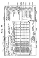
- FIG. 37 is a view for explaining the data structure of a manhour setting file 3601 ;
- FIG. 38 is a view for explaining the data structure of a standard data file 2804 ;
- FIG. 39 is a view showing the directory structure in the standard data file 2804 ;
- FIG. 40 is a view for explaining three routes of manhour setting in the standard manhour setting system 2801 ;
- FIG. 41 is a view for explaining the outline of data load in the standard manhour setting system 2801 ;
- FIG. 42 is a view for explaining the first route for setting the manhour on the basis of data from a standard material data file
- FIG. 43 is a view for explaining the second route for setting the manhour on the basis of data from an operation pattern data file
- FIG. 44 is a view showing a manhour setting file 3601 ;
- FIG. 45 is a view for explaining the initial menu window of the standard manhour setting system 2801 ;
- FIG. 46 is a view for explaining the window structure for defining the data range to be loaded in the standard manhour setting system 2801 ;
- FIG. 47 is a view showing the list of work data defined by the window shown in FIG. 46 ;
- FIG. 48 is a view for explaining the data load window
- FIG. 49 is a view for explaining that arbitrary works can be grouped by arbitrarily changing the hierarchical structure of directories in the standard manhour setting system 2801 ;
- FIG. 50 is a view for explaining the file structure of the standard manhour setting system 2801 ;
- FIG. 51 is a flow chart for explaining the control procedure of the standard manhour setting system 2801 ;
- FIG. 52 is a view for explaining a user interface window for selecting a “product” as a manhour setting target
- FIG. 53 is a view for explaining another user interface window for selecting a “product” as a manhour setting target
- FIG. 54 is a view for explaining the “model” selection window
- FIG. 55 is a view for explaining the dialog for selecting a “work” to be edited
- FIG. 56 is a view for explaining a work loaded by selection in FIG. 55 ;
- FIG. 57 is a view for explaining the analysis material editing window
- FIG. 58 is a view for explaining a user interface window for selecting a work to be analyzed
- FIG. 59 is a view for explaining a user interface window for displaying representative WFs (Work Factors) that can be selected by the user;
- FIG. 60 is a view showing a user interface window so as to explain the manhour definition of PU (pick up) operation
- FIG. 61 is a view showing a user interface window so as to explain the manhour definition of TURN (direction changing) operation;
- FIG. 62 is a view for explaining a window for inquiring the change reason for the manhour of a specific work
- FIG. 63 is a view showing a window for displaying the change reason for the manhour
- FIG. 64 is a view for explaining the basic operation of a work assignment system 2802 ;
- FIG. 65 is a view for explaining the file structure of the work assignment system 2802 ;
- FIG. 66 is a view for schematically explaining the work composition in the standard manhour setting system 2801 ;
- FIG. 67 is a view for explaining a window for displaying original data of simple division or parallel division in the standard manhour setting system 2801 ;
- FIG. 68 is a view for explaining the work contents of stations divided by simple division
- FIG. 69 is a view for explaining a user interface window in further editing the workshop divided by simple division;
- FIG. 70 is a view for explaining a user interface window for defining the parallel operation between works in parallel division
- FIG. 71 is a view for explaining a plurality of composition plans created by parallel division
- FIG. 72 is a view for explaining a user interface window in further editing composition plan 1 created by parallel division;
- FIG. 73 is a view for explaining a user interface window in further editing composition plan 2 created by parallel division;
- FIG. 74 is a view for explaining a user interface window for defining a load target in loading data from the standard manhour setting system 2801 in the work assignment system 2802 ;
- FIG. 75 is a view for explaining the reason why the data load range can be changed and defined in various ways in the work assignment system 2802 ;
- FIG. 76 is a view for explaining a user interface window in opening an existing file in a composition table file 6400 ;
- FIG. 77 is a view for explaining a state wherein the work data loaded in the memory of the work assignment system 2802 are displayed for each “target model”;
- FIG. 78 is a view for explaining a user interface window in adding a work in the standard manhour setting system 2801 ;
- FIG. 79 is a flow chart for explaining the control procedure of simple division by the work assignment system 2802 ;
- FIG. 80 is a view for explaining the states of five stations divided by simple division by the work assignment system 2802 ;
- FIG. 81 is a view for explaining work division in the stations in the work assignment system 2802 ;
- FIG. 82 is a view showing a state wherein a work having a large manhour is assigned to station 2 to be parallel-operated in the workshop having five stations so as to explain work assignment;
- FIG. 83 is a view for explaining the work division result in the stations in the work assignment system 2802 ;
- FIG. 84 is a view for explaining a user interface window for station division in the work assignment system 2802 ;
- FIG. 85 is a view for explaining a user interface window for adding or inserting a station in the work assignment system 2802 ;
- FIG. 86 is a view for explaining a method of displaying a station to which a work having a large manhour is assigned by the work assignment system 2802 ;
- FIG. 87 is a view for explaining an authentication window for authenticating a user who will compose works
- FIG. 88 is a block diagram for explaining the overall arrangement of a system according to a modification in which each subsystem has a standalone structure
- FIG. 89 is a view for explaining a state wherein operations of each of a plurality of works, and images and parameters corresponding to the respective operations are related to each other and stored;
- FIG. 90 is a view showing images (images representing a continuous operation) continuously generated by designating parameters in accordance with the method shown in FIG. 89 ;
- FIG. 91 is a view showing a dialog box for inputting a component symbol in relation to FIG. 39 ;
- FIG. 92 is a view showing a user interface window for grouping a plurality of works in composing works
- FIG. 93 is a view showing a user interface window for grouping a plurality of works in composing works
- FIG. 94 is a view showing a user interface window for grouping a plurality of works in composing works
- FIG. 95 is a flow chart for explaining a control procedure for work assignment as a modification to FIG. 79 , i.e., a composition control procedure that the number of stations assigned works preferentially should not exceed the number of stations N ST ;
- FIG. 96 is a flow chart for explaining a control procedure for work assignment as another modification to FIG. 79 , i.e., a composition control procedure for preferentially averaging the manhours of works assigned to stations;
- FIG. 97 is a view showing the state of parallel-operated station 2 in the workshop of the example shown in FIG. 85 .
- this assembly standard information management system comprises three subsystems:
- the work standard creation system 2800 creates (defines) a work standard (work standard data) for the standard manhour setting subsystem 2801 and work assignment subsystem 2802 .
- a work standard work standard data
- the user is required to understand, for each work to be executed in the manufacturing process, a “verb” representing an operation of the work, an “object” that describes the target of the work, and some “comments” and also have knowledge for the manufacturing process enough to sequentially describe the flow of the series of works.
- the standard manhour setting system 2801 determines the standard manhour for the work standard created by the work standard creation system 2800 .
- the work assignment system 2802 determines composition (work composition) using the work standard created by the work standard creation system 2800 .
- FIG. 1 shows the hardware configuration of the assembly standard information management system.
- this assembly standard information management system has a plurality of clients and one server (or a plurality of servers).
- the computer system of each client (to be referred to as a client system hereinafter) has, e.g.,
- the work standard creation system 2800 defines/creates master data to be used by the standard manhour setting system 2801 and work assignment system 2802 .
- a “work standard” represents a certain work unit in the manufacturing process.
- One work process (to be referred to as a process hereinafter) is formed from a plurality of work standards (or one work standard in some cases).
- a plurality of processes are defined for the products of the model, and one or a plurality of work standards are defined for each process, as shown in FIG. 2 .
- process 1 , process 2 , . . . , process N are defined for a representative model A.
- a plurality of “work standards” can be defined for each process.
- Each work standard is input through an input window (either from the client terminal or the server terminal) as shown in FIG. 3 .
- the basic work unit is called a “work standard” that is the base of work in the assembly process.
- the “assembly standard information management system” of this embodiment is finally a system for managing assembly of products in the factory and therefore is preferably capable of management not at the work standard level but at the product level.
- one work is assigned one identifier (or directory).
- Sets of a plurality of work standards are classified using a hierarchical structure including “target model”, “representative model” as the upper level thereof, and “genre” as the further upper level (e.g., a genre such as “printer” or “camera”). More specifically, the CRT window (display window) of the terminal displays menus:
- a dialog box for inputting the name of “representative model” and the name of “process” appears on the screen of the display unit.
- the user inputs the name of “representative model” and the name of “process”. For example, assume that the input name of “representative model” is “BJC-4200”, and the input name of “process” for the model “BJC-4200” is “total assembly”.
- the application program will create a record “total assembly” under a record “BJC-4200” and create a plurality of work standard records under the record “total assembly”.
- the main menu of the application program includes “work standard”, “edit”, . . . , and the pull-down menu of the “work standard” menu-includes “file new (N)”.
- the input window shown in FIG. 3 is displayed when the “file new (N)” is selected. That is, this application program allows the user to define a certain work of the representative model “BJC-4200” through the input window shown in FIG. 3 . The user inputs the name of the work in a “work name” field 312 .
- a window 300 shown in FIG. 3 has
- FIG. 4 shows files opened by this application program, which form a master data file group. Each master file will be described later.
- FIG. 5 is a flow chart for explaining the input procedure for the input window shown in FIG. 3 .
- an input to the “applied model” field 302 is done in step S 100 shown in FIG. 5 .
- the input in this step can be done in two ways: a direct input method by which the user directly inputs data to the field using a keyboard, and a menu input method by which an icon 301 is clicked to display a window with the list of a plurality of candidate names of the “applied models”, as shown in FIG. 6 , the user selects one of the displayed candidate names using a mouse or the like, and the selected name is input to the field 302 .
- a direct input method by which the user directly inputs data to the field using a keyboard
- a menu input method by which an icon 301 is clicked to display a window with the list of a plurality of candidate names of the “applied models”, as shown in FIG. 6 , the user selects one of the displayed candidate names using a mouse or the like, and the selected name is input to the field 302 .
- the names of a plurality of “applied models” selected in the window shown in FIG. 6 are input to the field 302 .
- step S 200 the user inputs a desired note to the note column through the keyboard.
- step S 300 the user inputs data related to parts or tools to a predetermined field through the keyboard while moving the cursor to an arbitrary position in the field using the mouse.
- a part number pairs with a part name When one of them is input, a part data master file 40 ( FIG. 4 ) is searched (so-called incremental search) using the input character sequence as a keyword, so all pairs of part numbers and part names having that keyword are displayed, as shown in FIG. 8 .
- the user selects a pair from the displayed candidates, so the selected pair data is output to a predetermined field.
- search is executed using characters input until the current time as a keyword to display candidates searched at the current time, and every time one more character is input, the candidates that have already been searched are narrowed down to only those matching the character sequence including the added character.
- step S 400 pieces of information related to tools and the like are input to the fields 306 , 307 , and 308 .
- the direct input using the keyboard and the method of searching from the master file (tool file 60 ) are prepared, like the input in step S 300 .
- step S 500 the user inputs details of a work standard for the work to be defined.
- the data input for definition of a work standard is the gist of the data input in the work standard creation system 2800 , and a dedicated input window as shown in FIG. 11 is prepared. Details of step S 500 are included in the control procedure shown in FIG. 14 .
- the input window shown in FIG. 11 is displayed.
- a work standard has already been input to the double-clicked position, i.e., when the user double-clicks on a portion where the name of an already input “work standard” is displayed, details of the already input work standard are displayed in the window shown in FIG. 11 .
- one “work standard” comprises
- “Comment 1 ” describes a comment about the “object”.
- “Comment 2 ” describes a comment about the “verb”. For example, if
- the work standard creation system 2800 prepares in advance a standard database 70 already input in relation to “comment 1 ”, a standard database 80 already input in relation to “object”, a standard database 90 already input in relation to “comment 2 ”, and a standard database 100 already input in relation to “verb”, as shown in FIG. 4 .
- the above-described incremental search method for the master databases corresponding to items that the user will input allows the user to execute reference input of already input data.
- defined standard terms can be input to the fields 1101 to 1104 regardless of the user.
- a field 1105 is divided into a reference instruction field 1105 a and a work standard display field 1105 b . “00*” is always displayed in the reference instruction field 1105 a . The user who requires the reference input should double-click on the field 1105 a.
- the user selects the field 1101 to notify the system that the user requires the data input of comment 1 .
- the fields 1101 to 1104 shown in FIG. 11 disappear, and instead, a field 1201 in which a keyword for search of a reference item can be input and a field 1202 in which a plurality of reference item candidates are to be displayed are displayed, as shown in FIG. 12 .
- the user does not know the standard verb for the operation “ (IDOUSASERU: move)” but knows that at least the character “ (DOU: move)” must be used.
- the user inputs “ (DOU: move)” to the field 1201 .
- the system searches the “verb” master database file 100 for all verb data having the character “ (DOU: move)”.
- the reference input is used for the input to all the fields 1101 to 1104 (steps S 506 to S 512 in FIG. 14 ).
- FIG. 15 shows that four work standards (procedures 01 to 04 ) are input.
- Each of the work standards can be assigned a note, as shown in FIG. 16 .
- a note is input to a field 1106 .
- the reference input function can also be used for the input of a note. More specifically, when the user wants to add a note to the already defined work standard 01 (displayed in the field 1105 b ), the user selects the field 1105 b using the mouse and then selects the field 1106 using the mouse. If the user individually requires the reference input, the user double-clicks on “00*” in the field 1105 a . Then, a field 1107 changes to a keyword input field 1601 and reference item display field 1602 , as shown in FIG. 16 . For example, when the user wants to refer to a note including a word “ (CHUI: note)”, the user inputs “ (CHUI: note)” to the field 1601 .
- the work standard creation system 2800 searches the note database 50 ( FIG. 4 ) and displays all notes including “ (CHUI: note) ” in the field 1602 , as shown in FIG. 16 .
- the user selects a desired note using the mouse and presses the ENTER key, the note is displayed in the field 1107 , as shown in FIG. 17 .
- an input data editing function is prepared as processing in step S 514 (FIG. 14 ).
- the number of the work standard to be changed is selected in the field 1107 , and the work standard is double-clicked. Then, the data of “comment 1 ”, “object”, “comment 2 ”, and “verb” assigned to the procedure are displayed in the fields 1101 to 1104 , respectively, and a note corresponding to the procedure is displayed in the field 1106 . The user individually corrects the data in each field.
- Editing each unit of the work standard means an-operation of deleting one work standard, an operation of setting the same work standard to another sequential position, or an operation of setting (inserting) a “free” work standard between two arbitrary work standards adjacent to each other.
- a menu 1802 shown in FIG. 18 is opened, for example, when the right mouse button of the client is clicked.
- editing functions including
- the target work standard is selected, and the “delete” menu is selected.
- the “copy” menu is selected.
- the sequential position is selected, and the “paste” menu is selected. With this “paste” operation, the contents of the work standard at the paste position are popped down.
- procedure 01 is selected in FIG. 18 , and the “add” menu is selected.
- work standards 01 to 03 sequentially move to procedure positions 02 to 04 , and a free procedure is set to procedure position 01 .
- the window returns to the window shown in FIG. 3 .
- the plurality of set work standards would be displayed in the field 310 , and the note would be displayed in the field 313 .
- the user gives a “work name” as a standard work to the plurality of work standards set in the field 310 . That is, the user inputs the work name to the field 312 .
- the assembly information management system can display a process set by the work assignment system 2802 at the site of work (client side). For example, when window display shown in FIG. 3 is done at the site of work, the operator can see the display and confirm the work contents, notes, tools, and parts at a glance. In this system, an image can be attached to each work standard in addition to the above character information for the work.
- FIG. 24 shows a window for inputting graphic data.
- This window is displayed when the user selects the “illustration” menu (menu on the right side of the “edit” menu”) in executing the application program of the work standard creation system 2800 , and a graphic pattern displayed in accordance with the selection operation can be edited.
- the image file to be edited is created in advance by a presentation application program PowerPoint (available from Microsoft) or Canvas and stored as a graphic file 120 .
- an illustration display column 2500 ( FIG. 25 ) is displayed.
- the user inputs the name of a file to be attached to a “file name” field 2501 in the display column 2500 .
- the system searches for the file whose name is input to the “file name” field 2501 and displays it in the column 2500 .
- an image file “so-09.wmf” is displayed at a position corresponding to the illustration display column 2500 shown in FIG. 25 as the result of user's file name input operation.
- the authoring tool for editing is selected, and then, the “edit” menu is clicked, as shown in FIG. 27 .
- the update result can be saved by clicking on an “update” icon 2602 (FIG. 26 ).
- the image is a still image in the BMP format.
- it may be a moving image compressed by MPEG.
- a so-called animation image may be stored in the graphic file 120 (FIG. 4 ).
- each animation image is stored with predetermined parameters unique to the operation of the image.
- An image with such parameters is registered in the graphic file 120 by combining the directory name, operation (verb) name, and parameters for each animation image, as shown in FIG. 89 .
- FIG. 90 shows an example in which three work standards:
- Assembly work is not always done only in Japan.
- This system for standardizing assembly work expects operation not only in Japan but also in many foreign factories (for example, factories in the English-speaking zone and Thai-speaking zone).
- the work standard creation system 2800 has a translation system 2803 .
- the translation system 2803 downloads master data created by the work standard creation system 2800 from the work standard creation system 2800 , and after translation, uploads the translated master data to the work standard creation system 2800 , as shown in FIG. 28 .
- the menu of the translation system 2803 includes “upload” for uploading work standard data to the master file, “work standard download” for downloading work standard data from the master file, and “work standard translation” for starting translation, as shown in FIG. 29 . Icons for switching the translation target between work standard and master data are also prepared.
- a window 3000 as shown in FIG. 30 is displayed to prompt the user to input a “representative model name” ( 3001 ) and “process name” ( 3002 ).
- a check box 3003 display of the entire text, display of only an untranslated portion, or display of only an error portion of translation is selected as the range of the display target.
- the translation language can be selected.
- the user clicks on a “display” icon button 3007 the names of all works having the model name input to the “representative model name” field 3001 and the process name input to the “process name” field 3002 are displayed in a display area 3005 .
- the translation system 2803 converts the Japanese to the English using a dictionary. Since this is conversion from words to words, a dictionary (table) is preferably used. Especially, since this work standard creation system 2800 uses the incremental search in inputting data, standard terms are used, and arbitrary word selection is eliminated, as described above. For this reason, the conversion accuracy improves.
- the work procedure (field 310 ) is manually input by the user. This is because the language structure of the Japanese is largely different from that of the English, and data (especially comment 1 and comment 2 ) constructing the work standard with high arbitrariness (i.e., close to a natural language) is unsuitable to conversion using a table.
- the translation system 2803 does not employ a translation method using language analysis (semantic analysis).
- language analysis semantic analysis
- a reason for this is as follows. In work management, many natural language texts are not always input. Translation is necessary only on a limited occasion when a work is to be newly defined, or work contents are to be changed, so machine translation that is expensive and time-consuming for maintenance is inappropriate. Between European languages (e.g., English and German) having relatively similar language structures, machine translation is appropriate even for the contents of work standards.
- a work standard is created using one language (e.g., on the Japanese side), and only software that runs on the WINDOWS (or WINDOWS NT) of Japanese version has the function of converting the Japanese text to English.
- converting various terms (text data) created by the work management system to the language of another country depends on the function of the language of the operating system based on the official language of that country. For this reason, conversion using a table is most reliable for easy translation to the language of that country.
- this translation system uses word conversion using a table (table dictionary) for a word in a work standard. Additionally, if the table dictionary also stores a converted word for a phrase longer than a word, the phrase is replaced with the converted word. In principle, a word in a work standard, which cannot be completely translated even using the table dictionary, is manually corrected.
- the name of the work is selected in the display area 3005 , and the “display” button 3007 is clicked. Then, a window as shown in FIG. 31 is displayed. Whether the translation has been appropriate is determined by checking the translation result. To verify the adaptability between a specific English word and a corresponding Japanese (adaptability of translation result), the word portion is double-clicked to display a correction window 3200 as shown in FIG. 32 .
- All work standards of the work with this work name are displayed in Japanese in an area 3202 .
- English work standards corresponding to these Japanese work standards are displayed in an area 3204 .
- work standard 01 is selected. This selected work standard 01 is displayed in Japanese in an area 3201 , and an English equivalent of procedure 01 is displayed in an area 3203 .
- the English text is corrected in the area 3202 .
- Data input in the work standard creation system 2800 and, more particularly, translation of work standards into the language of another country is done by word conversion and manual input.
- Manually inputting a translated text requires the user to have both an ability of translation and an ability of high-speed input using the keyboard. Since it may be difficult to ensure an operator who has both the abilities in that country, the translation operation and input operation are separated. That is, a translation result is recorded by voice input, and the data is input in playing back the recorded voice.
- a work standard to which input voice is to be attached is selected, and the “new” menu in the voice menu ( FIG. 33 ) of the translation system application program is selected, thereby displaying a window shown in FIG. 34 overlapping the window shown in FIG. 31 .
- the recording button ( ⁇ ) in the window shown in FIG. 34 is clicked, recording starts.
- the voice sampling rate and the like are set in advance.
- the ⁇ button is clicked.
- “save” in the “work standard” menu is selected.
- FIG. 35 shows the storage positions of files saved in the work standard creation system 2800 and translation system 2803 .
- Both the work standard creation system 2800 and translation system 2803 can process not only voice and image files but also, e.g., MOVIE files by QUICKTIME.
- a plurality of files temporarily registered, as shown in FIG. 35 can reproduced together (including voice and images). For example, when one or a plurality of work standards are selected in the window shown in FIG. 23 , and display in the “illustration” menu or “playback” in the voice menu is selected, the images/voices of the work standards are displayed/played back in the defined order.
- the voice and image are preferably synchronized.
- a QUICKTIME file or MOVIE file can easily synchronize voice and image.
- the work standard creation system 2800 also proposes to superpose CG data of an arrow or the like on still image data. During voice playback of a work, the arrow can visually indicate the operator in detail which work portion is being mentioned.
- the work assignment system 2802 to be described later composes the work standard data created by the work standard creation system 2800 , thereby assigning each work to a desired workshop. The result is reflected to a composition table file 6400 to be described later.
- the composition table file 6400 is uploaded to the work standard creation system 2800 .
- the work standard creation system 2800 can input works in the composition order corresponding to actual assembly workshops from the work assignment system 2802 and open the works.
- the uploaded file has voice data and image data attached by the work standard creation system 2800 .
- the voice/image playback function of the work standard creation system 2800 is exploited at the actual site of assembly, the work contents can be instructed to the operator in detail by voice and image.
- the work standard creation system 2800 describes a work related to a work standard by an operation phrase representing an operation of the work, an object phrase representing the target of the operation, and a comment phrase representing auxiliary information related to the operation or object.
- all work standards are standardized by the elements including the operation, object, and comment phrases.
- the work standard creation system 2800 is preferably built under a client/server computer system.
- a client/server distribution system for assembly information management is provided.
- the translation system 2803 can translate the operation, object, and comment phrases in each record of the standard manhour database into a predetermined language such that the system can operate in a country with a different language.
- AD-4 For translation by the translation system 2803 , a translation method using matching to a dictionary is employed in consideration of easiness.
- AD-5 Image data or voice data can be attached to a work standard.
- AD-6 Since not only a photorealistic image but also CG data or animation image can be used as image data, work standard data can be created at the initial stage quite before the actual operation of the factory.
- the standard manhour setting system 2801 is a system for determining the standard manhour of a desired work and is connected to the work standard creation system 2800 . More specifically, as shown in FIG. 28 , the standard manhour setting system 2801 and work standard creation system 2800 share master data and the like. Determination of the standard manhour by the standard manhour setting system 2801 is preferably done in the form of so-called batch processing. Hence, after master data including work standard data as the determination target is downloaded to the standard manhour setting system 2801 , the standard manhour setting system 2801 determines the standard manhour.
- the above-described work standard creation system 2800 does not input manhour data.
- the work standard creation system 2800 does not give a manhour value to a standard work because, in the standard work created by the work standard creation system 2800 , the manhour value given to each work must not vary depending on the person or day.
- the idea is that the manhour value is determined by the user who will compose works at the time of composition.
- the standard manhour setting system 2801 uses standard data as basic manhour data.
- the standard manhour setting system 2801 outputs a manhour setting file 3601 using, as reference files, a standard data (to be referred to as CS (C. Standard data) hereinafter) file 2804 and operation pattern data file 2806 .
- CS C. Standard data
- FIG. 37 shows the data structure of the manhour setting file 3601 .
- the manhour setting file 3601 shown in FIG. 37 has records in units of element works and has the names of the element works, the frequencies of the element works, the manhours of the element works (unit: RU), the values of “CS”, and the values of “set conditions”. More specifically, the value of the directory of a data file containing the contents of a set condition given to the work is stored in the “set condition” field. The value of the root directory of the set condition data file is stored in the “CS” field.
- FIG. 38 shows the data structure of the standard data file 2804 .
- Each record of the standard data file 2804 is called a standard material.
- each record of the standard data file 2804 has a “comment 1 ” field, “object” field, “comment 2 ” field, “verb” field, and “set condition” field.
- the “comment 1 ”, “object”, “comment 2 ”, and “verb” fields in the standard data file 2804 are the same as those in the work standard creation system 2800 . Set condition data will be described later.
- FIG. 39 shows examples of the data structure in the standard data file 2804 .
- standard material data 3901 of an element work has directories “SPG3/T133/M11/0”
- standard material data 3902 of another element work has directories “ASHD/T11222/T1111”.
- the operation pattern data file 2806 has the same data structure as that of the CS data file 2804 . More specifically, work data contained in the operation pattern data file 2806 include data as shown in FIG. 38 , which are related to works actually executed in the past. Only the difference from the standard data file 2804 is whether the work is recognized as a “standard”.
- the work standard creation system 2800 can easily define a number of element works as “work standards” each constituted by
- the work assignment system to be described later changes the composition of element works in consideration of the manhour. That is, the work standard creation system 2800 defines works, and the standard manhour setting system 2801 sets the manhour such that the composing operation by the work assignment system 2802 is facilitated.
- the work standard creation system 2800 , standard manhour setting system 2801 , and work assignment system 2802 commonly have work elements with identifiers. However, since the identifiers themselves do not make the user remember the work contents, the master files cannot be searched using the identifiers of work elements (standard works). Hence, this system is designed to be able to execute multi-keyword searching using, as keywords, a total of four phrases, i.e., two comments, object, and verb common to all the systems.
- the standard manhour setting system 2801 searches the standard material data file 2804 using the total of four phrases, i.e., two comments, object, and verb (the combination of these four keywords will be referred to as a “work identification multi-keyword” in this specification) and gives manhour data (the above-described “manhour” and “set condition”) attached to the found standard data to each work data of data created by the work standard creation system 2800 .
- step S 4001 work standard data created by the work standard creation system 2800 is loaded in step S 4001 .
- step S 4002 it is determined for each work whether data having work identification keywords matching (or partially matching or ambiguously matching) the work identification multi-keyword of the work is present in the standard material data file 2804 , and if so, manhour data HS of a record in the standard material data file is assigned to the work standard data.
- work data loaded from the work standard creation system 2800 is represented by X
- a work identification multi-keyword of the data X is represented by KW.
- step S 4004 the user has a chance to confirm whether the assigned manhour data HS is appropriate.
- step S 4002 it is determined in step S 4002 that the work identification multi-keyword KW of the work data X is not present in the standard material data file 2804 , a record having the work identification multi-keyword KW is searched for from the operation pattern data file 2806 in step S 4010 .
- the operation pattern data file 2806 has the same data structure as that of the standard material data file 2804 .
- the difference between the two files is that data in the operation pattern data file is not a standard but at least has manhour data set in the past.
- manhour data HP set for the work data is assigned to the target work.
- the user is given a chance to confirm whether the manhour data HP is correct.
- the standard manhour setting system 2801 has three routes to set manhour data.
- the route using the standard material data file 2804 is called a “first route”
- the route using the operation pattern data file 2806 is called a “second route”
- the route in which the user directly analyzes a work and assigns manhour data is called a “third route” for the descriptive convenience.
- FIG. 41 is a view for explaining for explaining data load in step S 4001 of FIG. 40 .
- FIG. 42 is a view for explaining the operation of the first route in detail.
- FIG. 43 is a view for explaining the operation of the second route.
- FIG. 44 is a view showing a detailed example of the final manhour setting file 3601 obtained by the operation in FIGS. 41 and 42 .
- FIG. 40 the operation of the first, second, or third route is performed every time a work data file is downloaded from the work standard creation system 2800 , i.e., every record of the work data file.
- FIGS. 41 to 44 show the operations as if the operation of the first, second, or third route were performed at once for all the downloaded files, for the illustrative convenience.
- the manhour setting file 3601 before data load has the data structure shown in FIG. 37 .
- the “comment 1 ” field, “object” field, “comment 2 ” field, and “verb” field in the work data file are loaded as an “element work name”. Since the work data file does not contain manhour data, the manhour setting file 3601 has no manhour data at the stage of data load in FIG. 41 .
- the Japanese texts in the “element work name” field of the manhour setting file 3601 shown in FIG. 41 are not translated to English, and English equivalents of these texts are indicated by * 1 to * 5 in the margin of FIG. 41 .
- This aims at indicating that when data in the respective columns of the table shown on the lower side of FIG. 41 , which are created by the work standard creation system 2800 , are directly loaded in this order, and the data in the row direction (horizontal direction) of the columns are connected, these data form significant Japanese texts in that word order in the “element work name” field.
- each “element work name” shown in FIG. 42 and the like is illustrated as a series of text data for the illustrative convenience, the “element work name” field is actually separated into the “comment 1 ” field, “object” field, “comment 2 ” field, and “verb” field.
- FIG. 42 explains the first route.
- standard data having the keyword KW “set load spring in treatment device for attaching load spring” is searched from the standard material data file 2804 .
- the “*” is a symbol representing a wild card and can have an arbitrary value.
- Data shown in the first record of the standard material data file 2804 shown in FIG. 42 are
- any word including “ (BANEO: spring)” can match in all records.
- any word including “ (NI: to)” can match in all records.
- any word including “ (KUMIKOMU: set)” can match in all records.
- the first record in the manhour setting file 3601 matches the first record in the standard material data file 2804 , which has
- the record matches a record having the highest degree of matching.
- the degree of matching is obtained with reference to the number of characters except the wild card.
- the first record in the standard material data file 2804 contains more matching text data than the second record. Hence, it is determined that the degree of matching is higher for the first record in the standard material data file 2804 than for the second record. It is finally determined that the record matches not the second record but the first record.
- the first record in the standard material data file 2804 has a time value “41 RU” as a manhour, so “ 41 ” is set in the “manhour” field of the first record of the manhour setting file 3601 .
- the first record in the standard material data file 2804 has ““SPG3/T133/M11/ 0 ” as “manhour standard material” data.
- the root directory of manhour information is “SPG3”, and the sub-directories are “T133/M11/ 0 ”.
- “SPG3” is stored in the “CS” field of the first record in the manhour setting file 3601
- data “T133/M11/ 0 ” is stored in the “set condition” field.
- the “degree of matching” is determined with reference to the number of matching words.
- the second record matches no record in the standard material data file 2804
- the third records matches the second record in the standard material data file 2804
- the fourth record matches no record in the standard material data file 2804
- the fifth record matches the third record in the standard material data file 2804 .
- the manhour setting file 3601 is tentatively created as shown in FIG. 42 in accordance with the manhour data setting procedure by the first route.
- the procedure of the second route is executed as shown in FIG. 43 .
- the text data of “element work names” of the second and fourth work data and the “comment 1 ”, “object”, “comment 2 ”, and “verb” in the operation pattern data file 2806 are searched.
- the second and fourth work data match the first and second records in the operation pattern data file 2806 , respectively.
- the values (“/GET-50E/M-10E” and “/GET-50E/M-10E”) of the “operation pattern” fields of the first and second records in the operation pattern data file 2806 are stored in the “set condition” fields of the second and fourth records in the setting file 3601 .
- the records do not match the standard material data file, no value is written in the “CS” fields in the setting file 3601 .
- the operation of the second route is ended.
- the manhour setting file 3601 is set as shown in FIG. 44 by the operations of the first and second routes.
- the operation of the third route is performed when the standard manhour can be determined by neither the first route nor the second route.
- the standard manhour is determined by directly analyzing the WF (Work Factor).
- FIG. 45 shows the initial menu window displayed when the standard manhour setting system 2801 is activated.
- six main menus are displayed.
- Data load is necessary before determination of the standard manhour.
- the user selects the data load menu 4501 , a window as shown in FIG. 46 is displayed.
- a field 4601 on the left side indicates product symbols created by the work standard creation system 2800 , i.e., product numbers (or the names of “representative models”) that can be downloaded to the manhour determination system.
- Fields 4602 to 4605 on the right side indicate work names downloaded from the work standard creation system 2800 in the past. More specifically, the field 4602 indicates the names of “work standards” downloaded by the standard manhour setting system 2801 , the field 4603 indicates the “product symbols” of the respective “work standards”, the field 6404 indicates the “names” of the respective “work standards”, and the field 4605 indicates download dates, i.e., “load dates”.
- One or a plurality of “product numbers” to be loaded (downloaded) are selected from the field 4601 using the mouse.
- the product number of the product to be named is designated in the field 4601 , and the “name” is input to a field 4601 .
- Data load is started by selecting the product to be loaded with the mouse, clicking on a “select” button 4611 , and clicking on an “OK” icon 4612 .
- the window shown in FIG. 47 displays the list of works present on the memory of the standard manhour setting system 2801 .
- a work downloaded previously can be discriminated from the current download data by referring to a previous load date field 4703 .
- the standard manhour setting system 2801 Since the standard manhour setting system 2801 is separated from the work standard creation system 2800 , works or work groups to be considered by the standard manhour setting system 2801 itself are present independently of works or work groups set by the work standard creation system 2800 . In the standard manhour setting system 2801 , one work (or work group) is independently recomposed by the standard manhour setting system 2801 as another “component”.
- the component newly set by the standard manhour setting system 2801 is discriminated from other components by a “component symbol”.
- the names of a plurality of works to be set in the component are selected in a field 4701 , the “component symbol set” menu in the edit menu is selected, and a component symbol (field 9101 ) and name (field 9102 ) are input through a window as shown in FIG. 91 .
- the component symbol is assigned to a field 4702 in FIG. 47 in correspondence with the selected work names.
- a flag 4705 a represents the state of work standard data.
- N the value of this flag
- C the value of the work standard is previously loaded to the standard manhour setting system 2801 and then changed on the standard manhour setting system 2801 side.
- D the value of the work standard is previously loaded to the standard manhour setting system 2801 and then deleted on the standard manhour setting system 2801 side.
- a field 4705 b has a flag representing the approval state of a work standard. When the value is “F”, it represents that the approver of the work standard is registered.
- a field 4706 represents a number assigned to the work standard by the work standard creation system 2800 .
- a field 4707 represents a number given to the work standard by the standard manhour setting system 2801 .
- Data is loaded in units of components.
- a “data load” window 4800 shown in FIG. 48 is displayed.
- the user designates the component symbol of a load target through a dialog 4801 in the window 4800 .
- the user checks the “all” button.
- the user checks the “designate component” button and inputs the component symbol name to a field 4802 .
- a work name selected in the field 4701 in FIG. 47 with the mouse is recognized as one “component”.
- a plurality of components can be defined.
- a single work can belong to different “components”.
- the window 4800 also has a dialog 4803 in which a material to be referred to in automatically setting the manhour. That is, after the data load, whether an operation of automatically setting the manhour for the loaded work should be performed can be designated by a “standard material (CS) check button 4804 and “analysis material” check button 4805 .
- the “standard material (CS)” is the standard material data file 2804
- automatic manhour setting by checking the “standard material (CS)” is manhour data setting by the above-described first route.
- the “analysis material” is the operation pattern data file 2806 , and automatic manhour setting by checking the “analysis material” is manhour data setting by the above-described second route. If the user does not want automatic manhour setting, both of the “standard material (CS)” and “analysis material” check buttons are turned off.
- FIG. 50 shows the file structure of the standard manhour setting system 2801 .
- the standard manhour setting system 2801 creates the manhour setting file 3601 on the basis of files loaded from the standard material data file 2804 and operation pattern data file 2806 .
- the standard material data file 2804 and analysis material “operation pattern” data file 2806 are created by a standard material creation routine 5001 and analysis material creation routine 5002 , respectively, in advance.
- manhour data is automatically set for work data downloaded from the work standard creation system 2800 .
- the respective “works” (the “works” are not the sets of a plurality of detailed works but simple root directories) required to assembly a product are linked by directories through one or a plurality of components (the components may be divided into a plurality of layers).
- the directories are traced, the “product” assembly work can finally reach a work, and which manhour data is set for the work can be confirmed.
- the program procedure of displaying work contents for this confirmation is included in the standard material manhour processing routine 5003 .
- the manhour data automatically set by the standard material creation routine 5001 or analysis material creation routine 5002 can also be confirmed by the standard material manhour processing routine 5003 .
- the standard material manhour processing routine 5003 will be described.
- Standard manhour processing is executed by clicking the “standard manhour processing” icon 4502 (FIG. 45 ).
- Individual “element works” correspond to work data and have a structure as shown in FIG. 38 , as described above.
- the standard material manhour processing routine 5003 is executed in accordance with the control procedure of the flow chart shown in FIG. 51 .
- the directories are linked using a hierarchical structure
- step S 600 the “product” as a manhour setting target is selected.
- FIG. 52 shows the product selection window.
- the target “product” is selected with the mouse or the like, and a “set manhour” button 5201 is clicked.
- step S 602 shows the “component” selection window.
- a target component is selected with the mouse or the like, and a “next” button 5301 is clicked.
- step S 604 shows the “model” selection window.
- “BJ-970909” and “97-09-09 load” are displayed as a product symbol and product name, respectively.
- “CH” is displayed as a component symbol.
- the target “model” is selected with the mouse or the like (“BJC-4300” is selected in the example shown in FIG. 54 ), and a “next” button 5401 is clicked.
- this button is clicked, the flow advances to step S 606 to select a “work” to be edited.
- FIG. 55 shows the dialog for causing the user to select a “work” to be edited.
- “product” and “component” since the user has selected the “product” and “component”, “BJ-970909” and “97-09-09 load” are displayed as a product symbol and product name, respectively.
- “CH” is displayed as a component symbol
- “BJC-4300” is selected as the “model”
- “xxxxxxx” are displayed as a set model symbol and model name, respectively.
- a plurality of works are displayed.
- the “formal management No” of each work is set.
- the “name” of each work is set.
- the manhour value set for each work is set.
- a field 5504 (“USE” field) stores the directory (corresponding to “set condition field” in the example shown in FIG. 43 ) of manhour set on the basis of automatic manhour setting by the second route, i.e., the operation pattern data file 2806 (this file is created on the basis of works used in the past).
- a field 5505 (“CS” field) stores the root directory (corresponding to “CS field” in the example shown in FIG. 42 ) of manhour set on the basis of automatic manhour setting by the first route, i.e., the standard material (CS) data file 2804 .
- the user can confirm manhour data (manhour value and manhour set condition (USE and CS)) automatically set. That is, in the manhour confirmation processes in step S 4004 and S 4014 of FIG. 40 are executed by the user through the display shown in FIG. 55 . More specifically, in the example shown in FIG. 55 , when a work has a value “0” as the “manhour” in the field 5503 , it means that no corresponding work is registered in either the standard material data file 2804 or operation pattern data file 2806 .
- step S 4004 when the manhour in the window shown in FIG. 55 is “0”, to automatically set the manhour by the second route, the user returns to the window shown in FIG. 48 to turn on the check box 4805 and click the OK button 4806 .
- step S 608 in FIG. 51 After the end of automatic manhour setting by the second route, the window shown in FIG. 55 is displayed again, and it is confirmed whether a work having a “manhour” value “0” is present. If a work having a manhour value “0” is present, processing from step S 608 in FIG. 51 is executed. Operations in step S 608 and S 610 correspond to step S 4020 and S 4022 in FIG. 40 (third route).
- Step S 608 in FIG. 51 is executed when the user clicks a “change” button 5506 to change the contents of the elements (comments, object, and verb) of a work or set the manhour value.
- FIG. 56 shows a user interface window for editing a work element.
- the comment 1 , object, comment 1 , and verb are corrected in fields 5601 to 5605 .
- the button 5605 is clicked.
- a button 5606 is clicked.
- a user interface window shown in FIG. 57 is displayed.
- the contents of each work are analyzed to determine the manhour using the third route.
- the control procedure shown in the flow chart of FIG. 51 is used for operation analysis in the third route.
- step S 610 is executed, and a user interface window shown in FIG. 58 is displayed.
- the user inputs a target operation content to a field 5801 and a WF (Work Factor symbol) to a field 5802 .
- a field 5803 stores the directory of a set condition.
- the analysis contents and set conditions obtained by analysis are stored in the set condition field 5803 as a directory including the data.
- a WF must be set for a work “set main body to a predetermined position”. To do this, the field 5802 is double-clicked.
- the WF is a known Work Factor symbol.
- a characteristic user interface window as shown in FIG. 59 is prepared to input the WF.
- a user interface window shown in FIG. 60 or 61 is displayed.
- a button corresponding to a WF in FIG. 59 a user interface window shown in FIG. 60 or 61 is displayed.
- WFs to be classified into a “table” type are WFs to be set in the user interface window as shown in FIG. 60 .
- WFs to be classified into a “table” type can be set in the user interface window as shown in FIG. 60 .
- WFs to be classified into a “formula” type are WFs to be classified into a “formula” type and can be analyzed in the user interface window as shown in FIG. 61 . Furthermore,
- WFs to be classified into a “table/formula” type are WFs to be classified into a “table/formula” type and can be analyzed in the above-described user interface windows as shown in FIGS. 60 and 61 .
- Each operation is analyzed by a condition related to the operation and a threshold value used to determine whether the condition is satisfied.
- a condition related to the operation For the “pickup” operation of the example shown in FIG. 60 , five (six at maximum in accordance with the display window size) conditions, “moving distance”, “grip type”, “pre-positioning”, “main size”, and “weight”, are preset.
- threshold values can be set for condition determination in accordance with the limited display window.
- threshold values “ ⁇ 10 cm”, “+10 cm”, and “>5 cm” are prepared for “moving distance”.
- Condition values are also preset for the remaining conditions, i.e., “grip type”, “pre-positioning”, “main size”, and “weight”. These condition and condition values (threshold values) are displayed when a “default value” button is clicked. For each condition, the user selects a condition value that is suggested to be most appropriate. In the example shown in FIG. 60 , the user selects
- the system calculates the manhour (time) for each condition. For example, for the condition value “+10 cm” for the condition “moving distance”, the moving speed of the worker is known, and time t 1 required for movement by 10 cm is set for the condition “moving distance”.
- manhour times t 2 , t 3 , t 4 , and t 5 are calculated, respectively, and the sum of times t 1 to t 5 is stored in a field 5804 as a manhour.
- a directory for storing the conditions and contents of condition values set in FIG. 60 is stored and displayed in the set condition field 5802 shown in FIG. 58 .
- FIG. 61 shows analysis definition for a formula-type WF using an example “TURN” (“change direction of body). More specifically, when time (i.e., unit time) necessary for one cycle of the operation “change direction of body” is “10”, a manhour for the operation “change direction of body” is generally represented by
- m is a variable representing the “number of times of operation of changing direction”.
- a manhour formula “10*m” is set for TURN (“change direction of body”) as a default value.
- the formula “10*m” is displayed in a field 6101
- the variable name “the number of times of operation of changing direction” is displayed in a field 6102
- the unit of the variable, “times” is displayed in a field 6104 .
- the user inputs the value of “times m” in a field 6103 .
- the manhour value is calculated, displayed in the manhour field 5804 in FIG. 58 , and stored in the memory.
- the manhour value may change.
- the standard manhour setting system 2801 monitors whether the manhour value changes using click on the “change” button 5508 as a trigger.
- a user interface window shown in FIG. 62 is displayed to allow the user to input the change reason for the manhour.
- a field 6201 contains “10” and indicates that the manhour change amount is “10”.
- a field 6202 has a USE value “0” and indicates that the work data is still unused.
- the change reason for the manhour is input to a field 6204 .
- the change reason is “new setting” because a work is newly registered.
- the reason code in a field 6203 is provided in a one-to-one correspondence with the change reason.
- a reason code with an arbitrary code can be assigned to the change reason.
- the reason code to be set is preferably determined in advance.
- buttons 6206 To display reasons for change in previous setting in the field 6204 in scroll, the user clicks on a button 6206 .
- the change reason code set in the user interface window shown in FIG. 62 is displayed together with various kinds of information set for the work. For example, in the display window shown in FIG. 55 , the reason code is displayed in a “correction” field 5507 (value “1”).
- This standard manhour setting system 2801 can hold the log of five changes (five or more if the memory allows) for one work.
- the column of the “correction” field 5507 of the work is double-clicked.
- a change log correction window shown in FIG. 63 is displayed.
- the change reason is displayed in a field 6301
- preceding and succeeding manhour values are displayed in a field 6302 .
- the work “electrical check” has only one change reason. However, when a plurality of change reasons are present, five change reasons are displayed at maximum while being stacked on the lower side.
- the work standard creation system 2800 creates work standard data containing no manhour data
- the standard manhour setting system 2801 creates the manhour setting file 3601 from the work standard data.
- the work assignment system 2802 downloads (loads data) the contents of the manhour setting file 3601 and creates a composition table file 6400 .
- the work assignment system 2802 also determines the range of composition in the loaded manhour setting data, composes works within that range in accordance with a predetermined purpose, corrects the composition, and outputs the composition. In other words, it may safely be said that the work standard creation system 2800 and standard manhour setting system 2801 exist such that the work assignment system 2802 can
- FIG. 65 illustrates inputs to the work assignment system 2802 and outputs from the work assignment system 2802 .
- the work assignment system 2802 receives the range to be composed as range data 6502 .
- Work data downloaded in accordance with this range is used for the composing operation.
- division condition data 6503 for division to stations is input as a condition for composition.
- Composition here means that a plurality of works in an order defined by the work standard creation system 2800 are distributed to a plurality of “stations” in accordance with the order of works (including a case wherein the order is changed by the work assignment system 2802 ).
- a station means a physical station or simply indicates a plurality of work groups put together in terms of concept. Each station is assigned a specific operator. In this assignment, the work assignment system 2802 assigns a specific operator on the basis of the information of each operator (experience time or the degree of skill for a work), which is stored in an operator database 6501 .
- the work assignment system 2802 outputs a simple division window display output 6504 or window display output 6505 (considering the parallel operation of works) to the display unit such that the user can easily confirm the composition result.
- the composition data can also be output in the EXCEL format as an example of a general document data format.
- the work assignment system 2802 provides two division methods as composition methods. As one method, works are simply divided to stations. As the other method, works are divided to stations in consideration of the parallel operation of the works (to be referred to as “parallel division” hereinafter for the descriptive convenience). For either division method, work data download from the standard manhour setting system 2801 to the work assignment system 2802 is necessary.
- FIG. 67 shows an example in which some works related to the assembly work of a model “GP55” are loaded to the work assignment system 2802 and displayed on the screen of the display unit.
- “standard No” represents the work order defined by the work standard creation system 2800 and edited or corrected by the standard manhour setting system 2801 .
- the work assignment system 2802 initially recognizes the order of work data in the manhour setting file 3601 of the standard manhour setting system 2801 as the work order in the work assignment system 2802 .
- simple division or parallel division is executed.
- the assembly work of one unit of model “GP55” comprises seven (or more) works
- WF unit: RU
- U the number of units (the number of products) to be produced by one crew as a set of a plurality of operators per day
- H unit: RU
- E the target composition efficiency (i.e., expected composition efficiency)
- N ST ( U ⁇ WF )/( H ⁇ E ) (1) That is, when N ST stations are prepared, the above object can be achieved.
- FIG. 68 shows a display window in which the works shown in FIG. 67 are divided to plurality of stations, and the work contents of station 1 (St 1 ) and station 2 (St 2 ) are displayed. More specifically, of the seven or more works shown in FIG. 67 , works Nos. 1 to 3 are assigned to station 1 (St 1 ) and works Nos. 4 to 6 are assigned to station 2 (St 2 ). In the example shown in FIG. 68 , the total manhour in station 1 (St 1 ) is 954 RU, and that in station 2 (St 2 ) is 750 RU. The total manhours “945 RU” and “750 RU” should fall within the pitch time T P .
- composition based on the theory may lower the efficiency.
- the work assignment system 2802 prepares a means for easily correcting/changing the contents of composition.
- the correction/change means is shown in FIG. 69 .
- FIG. 69 shows a user interface window as the correction/change means displayed on the display screen of the display unit of the work assignment system 2802 . More specifically, a bar graph 6901 represents the manhours (RU) assigned to the stations as a result of simple division. Reference numerals 6902 and 6903 denote contents of works assigned to the respective stations, which correspond to the graph 6901 .
- the bar representing the man hour of the station St 1 matches the pitch time T P
- the bars for the stations St 2 and St 3 are shorter than the pitch time T P
- the bar for a station St 4 exceeds the pitch time T P .
- a certain user may average the variation in manhour between the stations by exchanging the works between the stations.
- a certain user may empirically know that the efficiency can be improved by moving a specific work to another station although it increases the variation in manhour.
- a work in the station St 1 and a work in the station St 2 shown in the table 6902 can be exchanged.
- the variation result of the total manhour in each station in accordance with the exchange is reflected to the bar graph 6901 .
- the process change result can be visually confirmed on the bar graph.
- FIG. 70 shows a user interface window for defining the parallel operability of works.
- the example shown in FIG. 70 assumes an assembly procedure for a total of 14 works with numbers S (start) to 13 . Assume that the names, process number, and manhours of all works as shown in FIG. 67 are displayed on the display screen of the display unit for user confirmation.
- the user defines the parallel operation of works, which is known based on the experience of himself/herself, using work icons and link lines for connecting the work icons, as shown in FIG. 70 , while confirming the order of works on the table as shown in FIG. 67 .
- a work icon is symbolized by a circle and a work number in the circle.
- composition plan 1 composition plan 2 , . . . . and displays them, as shown in FIG. 71 .
- Group designation of works means that the same group code is given to a plurality of works to assign them to a single station.
- the group designation function is provided to designate works requiring the same tools to the same group or works using components on a single attachment surface to the same group to suppress the purchase cost for expensive tools, or designate works to the same group in order to put assembly works together to effectively use the machine manhour time for other works such that works having the same group code are prevented from being assigned to different stations.
- group designation that impedes assignment based on the priority table is not allowed, as shown in FIG. 94 .
- group 1 cannot be designated because work 8 outside the group is inserted between works 2 and 12 . This is because work 8 must be executed after work 2 and before work 12 and cannot be executed when work 8 is assigned to a station different from that for works 2 and 12 . To designate works 2 and 12 to the same group, work 8 inserted therebetween must also be designated to the same group.
- composition plan 1 works Nos. 1 , 2 , and 3 are assigned to station 1 (St 1 ), and works Nos. 4 , 5 , and 6 are assigned to station 2 (St 2 ).
- composition plan 2 works Nos. 1 , 2 , and 8 are assigned to station 1 (St 1 ), and works Nos. 3 , 4 , and 5 are assigned to station 2 (St 2 ).
- FIG. 72 shows a user interface for composition plan 1
- FIG. 73 shows a user interface for composition plan 2 .
- the work assignment system 2802 prepares two load sources of work data to be composed, i.e., the manhour setting file 3601 (standard manhour setting system 2801 side) and the composition table file 6400 (work assignment system 2802 side), as shown in FIG. 64 . More specifically, when the work assignment system 2802 is activated, and the “load new file (N)” menu of the file menu is selected, data can be loaded from the manhour setting file 3601 . When the “open (O)” menu of the file menu is selected, a target work file can be opened from the composition table file 6400 .
- FIG. 74 shows a user interface window for a data load when the “open new file (N)” menu is selected.
- the hierarchical relationship and contents of work data succeeded by the manhour setting file 3601 are edited or worked by the standard manhour setting system 2801 .
- Work data as the result must also be succeeded by the work assignment system 2802 from the standard manhour setting system 2801 .
- the work assignment system 2802 has a user interface capable of designating one or more or all of the four layers as data load targets from the standard manhour setting system 2801 .
- a user interface for example, to load data from the manhour setting file 3601 in units of genres, the name of the genre is input to a field 7401 , as in the example shown in FIG. 74 .
- a field 7402 a set of all work data at the “genre” level present in the field 6301 of the standard manhour setting system 2801 is displayed.
- bubble-jet printer BJ
- facsimile apparatus FAX
- laser beam printer LBP
- the name of a genre to which the representative model belongs is input to the field 7401 . Then, the names of all representative models belonging to the selected genre are displayed in a field 7404 . When, of these displayed names, the name of a desired “representative model” is double-clicked, the name is copied to a field 7403 , and then, the “OK” button 7408 is clicked.
- the name of the target model is input to a field 7405 , or a field 7406 is selected, and then, the “OK” button 7408 is clicked.
- the work assignment system 2802 has a user interface capable of setting to download a plurality of “components” at the “component” level at once.
- a field 7407 shown in FIG. 74 the names of all components belonging to a “target model” of a “representative model” in a “genre” are displayed, so a plurality of “components” can be selected while designating the download order thereof.
- sequential numbers are input to an order column 7409 of the “components” selected by clicking of the mouse.
- the user interface shown in FIG. 74 and , more particularly, arbitrary setting at the component level has the following advantage.
- model “X 3 ” (including the components “B”, “C”, and “A”), . . .
- the work assignment system 2802 adds “?n” (n is a number) to the directory name of the original “model”.
- FIG. 76 shows a user interface window for opening an existing file in the composition table file 6400 .
- files are selected in units of “target models”.
- the “target model” includes the “target model” defined in the field 7405 in FIG. 74 and the “target models” newly automatically defined in FIG. 75 .
- the “revision number ” of the selected “target model” is displayed in a field 7604 . Whether the composition data input window or composition data editing window for the selected “target model” is to be displayed is selected by check buttons 7605 .
- work data loaded to the memory of the work assignment system 2802 by the above-described download or file open operation are displayed in units of “target models”.
- the work data are displayed as a list in a field 7706 .
- the name of the target model is displayed in a field 7701
- the file name is displayed in a field 7702
- the revision number is displayed in a field 7703 .
- a “total work count” N TW for the “target model” is displayed in a field 7707
- the total manhour is displayed in a field 7708 .
- the number or name of a work selected in the field 7706 with the mouse is displayed in a field 7705 .
- the total manhour in composition is displayed in a field 7709 .
- An input for defining conditions for composition is done in a window 7710 .
- bibliographic data of the composition result are displayed in a window 7720 .
- Data_related to the above-described equation (1) are input to the input window 7710 . More specifically, the user inputs the number of units (the number of products) U to be produced by one crew as a set of a plurality of operators per day to a field 7710 a , time (i.e., operation time of each station) H (unit: RU) obtained by subtracting an exclusive time such as a break from one-day working time of one crew (a set of a plurality of operators) to a field 7710 b , and the target composition efficiency (i.e., expected composition efficiency) E to a field 7710 c .
- the total manhour in the composition which is represented by equation (1)
- the total manhour (field 7709 ) not input by the user but calculated by the system is used, as described above.
- the pitch time T P is displayed in a field 7720 d.
- the user can edit the composition in units of works while looking at the window shown in FIG. 77 .
- the editing commands are “divide”, “integrate”, “insert before”, “insert after”, “delete”, “change work order”, “in composition”, and “outside composition”. These editing menus are done from the editing menu provided by the window system or by selecting a desired work with the mouse and clicking the right button of the mouse.
- a work means that one unit work is divided into two unit works.
- the manhour value of each divided unit work is “0”.
- the number of each divided element work has a subnumber.
- the name of each divided element work has an indent.
- integrated works means that two element works are integrated to one unit work.
- the manhour of the integrated unit work corresponds to the sum of manhours of the respective element works as integration targets.
- a work designated by the dialog shown in FIG. 78 is inserted before a selected work. More specifically, the name of work to be inserted is written in a field 7801 , and a temporary manhour value is written to a field 7802 .
- composition or “outside composition” it is determined whether a work is to be subjected to composition or excluded from the composition targets.
- FIG. 79 is a flow chart for explaining the control procedure of composition.
- counters i, j, and k for work are initialized to “1”, and a register T for storing the accumulation time of manhours for each station is initialized to “0”.
- step S 791 data of a work wj (manhour tj) indicated by the counter j is extracted.
- step S 792 the manhour tj is accumulated to the time register T.
- step S 793 the counter j is incremented by one.
- step S 794 it is determined whether the manhour value accumulated in the time register T exceeds the pitch time T P . If NO in step S 794 , the flow returns to step S 791 to repeat the above-described operation.
- step S 796 the counter i is incremented to prepare for setting the next station.
- step S 797 the counter k is returned to “j”, and the time register T is initialized to “0”.
- step S 798 it is determined whether the counter value j representing the work number exceeds the total number of works N TW . If YES in step S 798 , the processing is ended.
- the control procedure shown in FIG. 79 determines assignment of works to stations with priority on the manhour. That is, assignment is determined that the accumulated manhour value T preferentially should not exceed the pitch time T P .
- the number of assigned stations may eventually be larger than the number of stations N ST set as a target, and if so, the composition efficiency changes accordingly.
- the assignment method shown in the flow chart of FIG. 95 gives priority on that the total number of stations to be assigned works should not exceed the upper limit value N ST .
- variables, a parallel number ni and total accumulated parallel sum number n 0 are newly introduced, unlike the control shown in FIG. 79 .
- the parallel number ni is the number of stations that can be parallel-operated in the stations i.
- step S 950 the counters i, j, and k for work are initialized to “1”, the register T for storing the accumulated time of manhours for each station is initialized to “0”, and the total accumulated parallel sum number n 0 is initialized to “0”.
- step S 951 data of the work wj (manhour tj) indicated by the counter j is extracted.
- step S 952 the manhour tj is accumulated to the time register T.
- step S 953 the counter j is incremented by one.
- step S 954 it is determined whether the manhour value for the station i exceeds the pitch time T P . Since the station i is allowed to parallel-operate ni stations in advance, and the manhour that can be assigned to the station i is T P ⁇ ni, more works can be assigned to the station i when T ⁇ T P ⁇ ni (4) When T ⁇ T P ⁇ ni (5) no more works can be assigned to the station i. In step S 954 , such determination is done.
- step S 955 i+n 0 ⁇ N ST (6) is determined to confirm that the total number of stations assigned works does not exceed the upper limit value N ST . More specifically, when equation (5) holds for a certain station i (the assigned manhour T exceeds the pitch manhour (T P ⁇ ni) considering parallel operation), the station Sti is newly set in step S 956 unless the total number of stations (i+n 0 ) set so far exceeds the upper limit value N ST .
- step S 955 is to prevent the number of assigned station from exceeding N ST by assigning works beyond the pitch manhour T P to the final station.
- step S 958 the counter k is set to “j”, and the time register T is initialized to “0”.
- step S 959 it is determined whether the counter value j representing the work number exceeds the total number of works N TW . If YES in step S 959 , the processing is ended.
- the load (manhour) may be concentrated to the final station.
- the assignment method shown in the flow chart of FIG. 96 has as its object to keep the number of stations N ST set as a target and distribute the load (manhour) without concentrating the load to the final station such that the variation in manhour between the stations is easily evened.
- T 0 be the accumulated manhour assigned to all stations assigned works.
- a new variable, station manhour T A is introduced.
- T A WF/N ST (8)
- the pitch time T P defined by equations (1) and (2) is used as a reference for determination whether the station Sti is to be set.
- the station manhour average value T A defined by equation (8) is used as data for determination whether the station Sti is to be set.
- step S 960 of FIG. 96 the counters i, j, and k for work are initialized to “1”, the register T for storing the accumulated time of manhours for the station i is initialized to “0”, the total accumulated manhour T 0 is initialized to “0”, and the total accumulated parallel sum number n 0 is initialized to “0”.
- step S 961 data of the work wj (manhour tj) indicated by the counter j is extracted.
- step S 962 the manhour tj is accumulated to the time register T. That is, the accumulated manhour value of the manhours tk to tj for the station i is stored in the time register T.
- step S 963 the manhour tj is accumulated to the time register T 0 to update the total accumulated manhour T 0 .
- step S 964 the counter j is incremented by one.
- step S 964 it is determined whether T 0 >T A ⁇ ( i+n 0 ) (10) As described above, (i+n 0 ) is the total number of stations assigned works so far in determining whether the ith station is to be set. For this reason, when equation (10) holds, all works corresponding to the accumulated manhour Ti can be assigned to the station Sti in step S 965 .
- FIG. 80 shows an example in which the composition created by the control procedure shown in FIG. 79 is displayed.
- composition can be easily corrected, as described in association with FIG. 69 , and also, correction can be done while confirming the correction process in real time.
- FIG. 80 the work assignment states of five out of the total of N ST stations are displayed.
- the number of stations for display is limited to five due to a limitation on the screen size of the display unit.
- the total manhour value of each station is stored and displayed in a field 8004 .
- the total manhour of each station is displayed in a bar graph ( 8006 ).
- the composition efficiency is displayed in a field 8007 .
- Reference numeral 8008 denotes a display window of works outside the composition; and 8009 , a display example of a menu displayed by clicking the right button of the mouse. The work outside the composition and the works listed for the station can be exchanged.
- the editing commands “divide”, “integrate”, “insert before”, “insert after”, “delete”, “change work order”, “in composition”, and “outside composition” are allowed for works displayed in the composition target definition window shown in FIG. 77 .
- editing commands “divide”, “integrate”, “insert before”, “insert after”, “delete”, “change work order”, “in composition”, and “outside composition” are also prepared for the works listed for the five stations displayed on the window shown in FIG. 80 .
- the “change work order” menu is displayed as a “move” menu.
- FIG. 81 Assume that a plan as shown in FIG. 81 is obtained by a composing operation. As is apparent from the example shown in FIG. 81 , the total manhour of station 1 is larger than that of station 2 by 38 RU. The cause for this is the work “A 4 ” assigned to station 1 , as is known from the work table.
- the user selects the work “A 4 ” with the mouse, displays the menu by clicking the right button of the mouse, and selects the “divide” menu (or double-clicks).
- the work “A 4 ” is divided into works “A 4 - 1 ” and “A 4 - 2 ” each having a 1 ⁇ 2 manhour, as shown in FIG. 82 .
- the user selects the “move” menu to move the work “A 4 - 2 ” from station 1 to station 2 .
- the result of movement is reflected to the graph, as shown in FIG. 83 .
- a desired work is selected with the mouse, and the menu is selected (for “integrate”, the menu can also be double-clicked), thereby reflecting the editing result to the graph.
- the editing function in the work assignment system 2802 includes not only editing in units of work but also editing in units of stations.
- the functions are “delete”, “insert”, “add”, and “parallel integrate” of a station.
- an empty station is inserted between two stations.
- an arbitrary work in the station located on the front side is selected with the mouse.
- the right button of the mouse is clicked to display the “insert station” menu, and the menu is selected. With this operation, an empty station is inserted.
- add station a station is added next to the station as an addition target.
- an arbitrary work in the station as an addition target is selected with the mouse.
- the right button of the mouse is clicked to display the “add station” menu, and the menu is selected.
- an empty station is added.
- the newly created station is additionally displayed after the station as the addition target. Since the added station has no work, a work is moved from another station.
- a work in a station is divided into stations equal in number to the plurality of operators.
- a desired station is selected with the mouse, the right button of the mouse is clicked to display the “parallel integrate” menu, and the menu is selected. Then, a dialog shown in FIG. 84 is displayed. The number of stations to be divided is written in a field 8402 .
- FIG. 85 shows an example of station division before parallel operation.
- the number of works assigned to the station St 2 displayed as “operator 2 ” is large, and the time is also long.
- station 2 is divided into stations St 2 - 1 and St 2 - 2 , as shown in FIG. 97 .
- St 1 expressed as “operator 1 ” in FIG. 85 corresponds to St 1 expressed as “operator 1 ” in FIG. 97 .
- St 3 expressed as “operator 3 ” in FIG. 85 corresponds to St 3 expressed as “operator 4 ” in FIG. 97 .
- St 4 expressed as “operator 4 ” in FIG. 85 corresponds to St 4 expressed as “operator 5 ” in FIG. 97
- St 5 expressed as “operator 5 ” in FIG. 85 corresponds to St 5 expressed as “operator 6 ” in FIG. 97 .
- Addition of a station (or addition of a work) at the time of composition is effective when a station (or work) for check (inspection) is to be added. Whether the inspection process is necessary can hardly be determined by the work standard creation system 2800 for defining the work or the standard manhour setting system 2801 for defining the manhour. Such determination is necessary and possible when the work assignment system 2802 is operated.
- a previous or subsequent station as an addition target is designated with the mouse, and the “add” station menu is selected, a newly created empty station is displayed after the addition target station.
- composition is not limited to the above examples.
- the display shown on the upper side ( 8601 ) of FIG. 86 is not preferable because the window is inefficiently occupied.
- n be a value obtained by dividing the total manhour in the station assigned such a single work having a large manhour by a number (to be referred to as a unit manhour hereinafter) obtained by multiplying the pitch time T P by a predetermined value (a constant can be used), and rounding up the quotient, n operators are assigned to the station.
- the graph display of the manhour of such a station has a width n times the normal bar width.
- the width of the station 2 bar in FIG. 86 is doubled ( 8602 in FIG. 86 ). With this display, the user can understand at a glance that the station has a single work with a large manhour, and its manhour represented by a multiple of the above “unit manhour”.
- the user interface window shown in FIG. 87 is an input window for checking the operator has a right for composition.
- the operator code is input to a person name code column 8701 , the name of the operator is input to a column 8702 , the position is input to a column 8703 , the password is input to a column 8704 , and the authority is input to a column 8705 .
- the input data are collated with a personnel database, and only when the data match, an access right is given.
- FIG. 88 shows the data upload from the work assignment system 2802 to the work standard creation system 2800 when the work standard creation system 2800 , standard manhour setting system 2801 , and work assignment system 2802 have standalone structures.
- the work standard creation system 2800 of this embodiment can attach voice or image data to a work standard.
- the work standard creation system 2800 , standard manhour setting system 2801 , and work assignment system 2802 build a client/server database system, as shown in FIG. 1 . For this reason, the download or upload by batch operation of work standard data is unnecessary between the work standard creation system 2800 , standard manhour setting system 2801 , and work assignment system 2802 .
- download or upload is limited to download or upload of minimum necessary data. Merging between image data or voice data and work standard data composed by the work assignment system 2802 is executed by the work standard creation system 2800 . This shortens the time required for the download or upload.
- work standard creation system 2800 can be connected to each station in the workshop through a LAN (communication network), so work standard data, including image data or voice data, can be downloaded to the workstation of each station through the LAN.
- LAN communication network
- M-1 The above-described embodiment is constructed under the client/server environment, as shown in FIG. 1 .
- the present invention can also be applied to a standalone environment in a single computer system.
- the work standard creation system 2800 , standard manhour setting system 2801 , and work assignment system 2802 operate in the computer system.
- M-2 various files are created in each system, and the formats of these files can be set in various ways.
- these files need not always be so-called permanent files always stored in an external auxiliary storage device such as a disk and can be so-called view files which are present only on the main memory. This is because many files are temporarily created for the purpose of display (view).
- the object of the present invention can also be achieved by supplying a storage medium (or recording medium) in which software program codes for realizing the functions of the above-described embodiment are recorded to an apparatus which operates as the above-described subsystem or the server/client, and causing the computer (or a CPU or an MPU) of the system or apparatus to read out and execute the program codes stored in the storage medium.
- the program codes read out from the storage medium realize the functions of the above-described embodiment by themselves, and the storage medium storing the program codes constitutes the present invention.
- the functions of the above-described embodiment are realized not only when the readout program codes are executed by the computer but also when the OS (Operating System) running on the computer performs part or all of actual processing on the basis of the instructions of the program codes.
- management can be more efficiently executed using work standard data suitable for computer processing.
- work standard data suitable for computer processing can be created.
- the manhour can be quickly set for a work standard by computer processing.
Landscapes
- Business, Economics & Management (AREA)
- Human Resources & Organizations (AREA)
- Engineering & Computer Science (AREA)
- Strategic Management (AREA)
- Economics (AREA)
- Entrepreneurship & Innovation (AREA)
- Development Economics (AREA)
- Educational Administration (AREA)
- Operations Research (AREA)
- Marketing (AREA)
- Game Theory and Decision Science (AREA)
- Quality & Reliability (AREA)
- Tourism & Hospitality (AREA)
- Physics & Mathematics (AREA)
- General Business, Economics & Management (AREA)
- General Physics & Mathematics (AREA)
- Theoretical Computer Science (AREA)
- Information Retrieval, Db Structures And Fs Structures Therefor (AREA)
- General Factory Administration (AREA)
- Management, Administration, Business Operations System, And Electronic Commerce (AREA)
Applications Claiming Priority (2)
| Application Number | Priority Date | Filing Date | Title |
|---|---|---|---|
| JP2000001076A JP2001195115A (ja) | 2000-01-06 | 2000-01-06 | 工数自動設定システム、工数自動設定方法、分散型クライアントサーバシステム及びコンピュータプログラムの記憶媒体 |
| JP2000-001076 | 2000-01-06 |
Publications (2)
| Publication Number | Publication Date |
|---|---|
| US20020059225A1 US20020059225A1 (en) | 2002-05-16 |
| US6934704B2 true US6934704B2 (en) | 2005-08-23 |
Family
ID=18530337
Family Applications (1)
| Application Number | Title | Priority Date | Filing Date |
|---|---|---|---|
| US09/753,726 Expired - Fee Related US6934704B2 (en) | 2000-01-06 | 2001-01-03 | Automatic manhour setting system and method, distributed client/server system, and computer program storage medium |
Country Status (3)
| Country | Link |
|---|---|
| US (1) | US6934704B2 (ja) |
| JP (1) | JP2001195115A (ja) |
| DE (1) | DE10100275A1 (ja) |
Cited By (4)
| Publication number | Priority date | Publication date | Assignee | Title |
|---|---|---|---|---|
| US20080091674A1 (en) * | 2006-10-13 | 2008-04-17 | Thomas Bradley Allen | Method, apparatus and article for assigning a similarity measure to names |
| US20090063125A1 (en) * | 2007-08-28 | 2009-03-05 | International Business Machines Corporation | Method for globalizing support operations |
| US20090240539A1 (en) * | 2008-03-21 | 2009-09-24 | Microsoft Corporation | Machine learning system for a task brokerage system |
| US20150199809A1 (en) * | 2014-01-16 | 2015-07-16 | Fujitsu Fsas Inc. | Management apparatus and management method |
Families Citing this family (3)
| Publication number | Priority date | Publication date | Assignee | Title |
|---|---|---|---|---|
| JP5178496B2 (ja) * | 2008-12-22 | 2013-04-10 | 三菱電機株式会社 | プロジェクト管理システム |
| JP6138566B2 (ja) * | 2013-04-24 | 2017-05-31 | 川崎重工業株式会社 | 部品取付作業支援システムおよび部品取付方法 |
| JP6696305B2 (ja) * | 2016-06-02 | 2020-05-20 | コニカミノルタ株式会社 | 患者情報表示装置及び患者情報表示方法 |
Citations (23)
| Publication number | Priority date | Publication date | Assignee | Title |
|---|---|---|---|---|
| US4845634A (en) | 1987-07-29 | 1989-07-04 | Westinghouse Electric Corp. | Product information network system |
| US4961148A (en) | 1989-02-06 | 1990-10-02 | Chrysler Corporation | Method for preparing automotive assembly operations documents |
| US5010486A (en) | 1986-11-28 | 1991-04-23 | Sharp Kabushiki Kaisha | System and method for language translation including replacement of a selected word for future translation |
| US5023800A (en) | 1988-04-14 | 1991-06-11 | Northrop Corporation | Assembly data model system |
| US5177688A (en) | 1989-12-01 | 1993-01-05 | Texas Instruments Incorporated | Assembly line balancer |
| JPH08305748A (ja) | 1995-04-28 | 1996-11-22 | Dainippon Printing Co Ltd | 作業工数見積り装置 |
| DE19632499A1 (de) | 1995-08-11 | 1997-03-06 | Hartmut F Prof Dr Ing Binner | Verfahren zur graphischen Darstellung von Prozessen |
| US5615138A (en) | 1993-04-08 | 1997-03-25 | Honda Giken Kogyo Kabushiki Kaisha | Method for establishing the working mantime in the production line |
| US5767848A (en) * | 1994-12-13 | 1998-06-16 | Hitachi, Ltd. | Development support system |
| US5771043A (en) | 1990-08-22 | 1998-06-23 | Hitachi, Ltd. | Method and apparatus for displaying operating procedure |
| US5884247A (en) | 1996-10-31 | 1999-03-16 | Dialect Corporation | Method and apparatus for automated language translation |
| US5930460A (en) * | 1995-01-24 | 1999-07-27 | Nissan Motor Co., Ltd. | Teaching program automatic generation apparatus |
| US5980084A (en) | 1997-11-24 | 1999-11-09 | Sandia Corporation | Method and apparatus for automated assembly |
| US6163785A (en) | 1992-09-04 | 2000-12-19 | Caterpillar Inc. | Integrated authoring and translation system |
| US6173253B1 (en) | 1998-03-30 | 2001-01-09 | Hitachi, Ltd. | Sentence processing apparatus and method thereof,utilizing dictionaries to interpolate elliptic characters or symbols |
| US6208956B1 (en) | 1996-05-28 | 2001-03-27 | Ricoh Company, Ltd. | Method and system for translating documents using different translation resources for different portions of the documents |
| US6223092B1 (en) | 1990-02-14 | 2001-04-24 | Hitachi, Ltd. | Automatic manufacturing evaluation method and system |
| US6240328B1 (en) | 1994-01-10 | 2001-05-29 | Motorola, Inc. | Manufacturing method for assembling products by generating and scheduling dynamically assembly instructions |
| US6249715B1 (en) | 1997-03-18 | 2001-06-19 | Sumitomo Wiring Systems, Ltd. | Method and apparatus for optimizing work distribution |
| US6385621B1 (en) * | 1998-11-20 | 2002-05-07 | Franklin Peter Frisina | Computer software for maintenance resource management |
| US6453209B1 (en) | 1999-09-01 | 2002-09-17 | Daimlerchrysler Corporation | Computer-implemented method and apparatus for integrating vehicle manufacturing operations |
| US6490569B1 (en) * | 1998-06-22 | 2002-12-03 | Km Ltd. | System for combining life cycle assessment with activity based costing using a relational database software application |
| US20030023611A1 (en) | 1999-03-18 | 2003-01-30 | Lockheed Martin Corporation | Relational database method for accessing information useful for the manufacture of, to interconnect nodes in, to repair and to maintain product and system units |
-
2000
- 2000-01-06 JP JP2000001076A patent/JP2001195115A/ja not_active Withdrawn
-
2001
- 2001-01-03 US US09/753,726 patent/US6934704B2/en not_active Expired - Fee Related
- 2001-01-04 DE DE10100275A patent/DE10100275A1/de not_active Ceased
Patent Citations (23)
| Publication number | Priority date | Publication date | Assignee | Title |
|---|---|---|---|---|
| US5010486A (en) | 1986-11-28 | 1991-04-23 | Sharp Kabushiki Kaisha | System and method for language translation including replacement of a selected word for future translation |
| US4845634A (en) | 1987-07-29 | 1989-07-04 | Westinghouse Electric Corp. | Product information network system |
| US5023800A (en) | 1988-04-14 | 1991-06-11 | Northrop Corporation | Assembly data model system |
| US4961148A (en) | 1989-02-06 | 1990-10-02 | Chrysler Corporation | Method for preparing automotive assembly operations documents |
| US5177688A (en) | 1989-12-01 | 1993-01-05 | Texas Instruments Incorporated | Assembly line balancer |
| US6223092B1 (en) | 1990-02-14 | 2001-04-24 | Hitachi, Ltd. | Automatic manufacturing evaluation method and system |
| US5771043A (en) | 1990-08-22 | 1998-06-23 | Hitachi, Ltd. | Method and apparatus for displaying operating procedure |
| US6163785A (en) | 1992-09-04 | 2000-12-19 | Caterpillar Inc. | Integrated authoring and translation system |
| US5615138A (en) | 1993-04-08 | 1997-03-25 | Honda Giken Kogyo Kabushiki Kaisha | Method for establishing the working mantime in the production line |
| US6240328B1 (en) | 1994-01-10 | 2001-05-29 | Motorola, Inc. | Manufacturing method for assembling products by generating and scheduling dynamically assembly instructions |
| US5767848A (en) * | 1994-12-13 | 1998-06-16 | Hitachi, Ltd. | Development support system |
| US5930460A (en) * | 1995-01-24 | 1999-07-27 | Nissan Motor Co., Ltd. | Teaching program automatic generation apparatus |
| JPH08305748A (ja) | 1995-04-28 | 1996-11-22 | Dainippon Printing Co Ltd | 作業工数見積り装置 |
| DE19632499A1 (de) | 1995-08-11 | 1997-03-06 | Hartmut F Prof Dr Ing Binner | Verfahren zur graphischen Darstellung von Prozessen |
| US6208956B1 (en) | 1996-05-28 | 2001-03-27 | Ricoh Company, Ltd. | Method and system for translating documents using different translation resources for different portions of the documents |
| US5884247A (en) | 1996-10-31 | 1999-03-16 | Dialect Corporation | Method and apparatus for automated language translation |
| US6249715B1 (en) | 1997-03-18 | 2001-06-19 | Sumitomo Wiring Systems, Ltd. | Method and apparatus for optimizing work distribution |
| US5980084A (en) | 1997-11-24 | 1999-11-09 | Sandia Corporation | Method and apparatus for automated assembly |
| US6173253B1 (en) | 1998-03-30 | 2001-01-09 | Hitachi, Ltd. | Sentence processing apparatus and method thereof,utilizing dictionaries to interpolate elliptic characters or symbols |
| US6490569B1 (en) * | 1998-06-22 | 2002-12-03 | Km Ltd. | System for combining life cycle assessment with activity based costing using a relational database software application |
| US6385621B1 (en) * | 1998-11-20 | 2002-05-07 | Franklin Peter Frisina | Computer software for maintenance resource management |
| US20030023611A1 (en) | 1999-03-18 | 2003-01-30 | Lockheed Martin Corporation | Relational database method for accessing information useful for the manufacture of, to interconnect nodes in, to repair and to maintain product and system units |
| US6453209B1 (en) | 1999-09-01 | 2002-09-17 | Daimlerchrysler Corporation | Computer-implemented method and apparatus for integrating vehicle manufacturing operations |
Non-Patent Citations (9)
| Title |
|---|
| Driskill et al., "Interactive Design, Analysis, and Illustration of Assemblies", Proceeding of the 1995 symposium on the interactive 3D graphics, 1995, pp. 27-33. |
| English Abstract of German Patent Publication 196 32 499 A1 (Item A). |
| English Abstract of Japanese Publication 8-305748 (Item B). |
| English Translation of German Patent Publication 196 32 499 A1. |
| German Patent Office Communication for Application No. 101 00 274.2-53. |
| German Patent Office Communication for counterpart Application No. 101 00 275.2-53. |
| He et al., "On a system of understanding illustrative diagrams in an assembly manual", Proceedings of the 3rd international conference on Industrial and engineering applications of artificial intelligence and expert systems, 1990, pp. 350-356. |
| Translation of German Patent Office Communication for Application No. 101 00 274.2-53 (Item AA). |
| Translation of German Patent Office Communication for Application No. 101 00 275.2-53 (Item CC). |
Cited By (7)
| Publication number | Priority date | Publication date | Assignee | Title |
|---|---|---|---|---|
| US20080091674A1 (en) * | 2006-10-13 | 2008-04-17 | Thomas Bradley Allen | Method, apparatus and article for assigning a similarity measure to names |
| US9026514B2 (en) * | 2006-10-13 | 2015-05-05 | International Business Machines Corporation | Method, apparatus and article for assigning a similarity measure to names |
| US20090063125A1 (en) * | 2007-08-28 | 2009-03-05 | International Business Machines Corporation | Method for globalizing support operations |
| US7962324B2 (en) | 2007-08-28 | 2011-06-14 | International Business Machines Corporation | Method for globalizing support operations |
| US20090240539A1 (en) * | 2008-03-21 | 2009-09-24 | Microsoft Corporation | Machine learning system for a task brokerage system |
| US20150199809A1 (en) * | 2014-01-16 | 2015-07-16 | Fujitsu Fsas Inc. | Management apparatus and management method |
| US9524528B2 (en) * | 2014-01-16 | 2016-12-20 | Fujitsu Fsas Inc. | Management apparatus and management method |
Also Published As
| Publication number | Publication date |
|---|---|
| US20020059225A1 (en) | 2002-05-16 |
| DE10100275A1 (de) | 2001-10-31 |
| JP2001195115A (ja) | 2001-07-19 |
Similar Documents
| Publication | Publication Date | Title |
|---|---|---|
| US7136825B2 (en) | Work assignment system and method, distributed client/server system, and computer program storage | |
| US20050240390A1 (en) | Work standard creation system and method, distributed client/server, and computer program storage medium | |
| US5119307A (en) | Method and system for automated bill-of-material generation | |
| US5909688A (en) | Information management system | |
| US7054826B2 (en) | Assembly information management system and client/server distribution system for assembly information management | |
| US20050038821A1 (en) | Method and system for capturing, managing and disseminating manufacturing knowledge | |
| US5303147A (en) | Computer aided planning method and system | |
| KR19980702170A (ko) | 통신네트워크 데이터베이스 구축 방법 및 장치 | |
| US6934704B2 (en) | Automatic manhour setting system and method, distributed client/server system, and computer program storage medium | |
| US6745195B1 (en) | System, method and computer program product for generating software cards that summarize and index information | |
| US5513356A (en) | Information processing system for obtaining desired processing based upon output specifications input by user | |
| US6920364B2 (en) | Work assistance apparatus and memory medium for use therein | |
| US20060010081A1 (en) | Automated system for assisting the architectural process | |
| US7664780B1 (en) | Process data development and analysis system and method | |
| US5715442A (en) | Data unit group handling apparatus | |
| JPH08234977A (ja) | ソフトウェアプロジェクトにおける多面的進捗管理方式 | |
| JP3036720B2 (ja) | 階層化データ検索装置及び保守部品検索装置 | |
| JPH11184687A (ja) | ソフトウェア文書の階層構造及び関係を用いるソフトウエア文書作成システムとその運用方法 | |
| JPS6284337A (ja) | 仕様書情報解析方式 | |
| JPH06214768A (ja) | プログラム部品作成方法及びプログラム自動生成方法 | |
| JP3695410B2 (ja) | 生産技術の管理方法及びそのための装置 | |
| JP3123400B2 (ja) | 資産修正履歴自動生成システム | |
| JPH08202769A (ja) | ドキュメント作成装置 | |
| JPH11306253A (ja) | データ処理作業の進行管理システム | |
| WO2003019429A1 (en) | Management system |
Legal Events
| Date | Code | Title | Description |
|---|---|---|---|
| AS | Assignment |
Owner name: CANON KABUSHIKI KAISHA, JAPAN Free format text: ASSIGNMENT OF ASSIGNORS INTEREST;ASSIGNORS:OKADA, ATSUSHI;HIRASHIMA, TAKASHI;SAWAMURA, YOSHINORI;AND OTHERS;REEL/FRAME:011824/0845;SIGNING DATES FROM 20010126 TO 20010205 |
|
| FPAY | Fee payment |
Year of fee payment: 4 |
|
| FPAY | Fee payment |
Year of fee payment: 8 |
|
| REMI | Maintenance fee reminder mailed | ||
| LAPS | Lapse for failure to pay maintenance fees |
Free format text: PATENT EXPIRED FOR FAILURE TO PAY MAINTENANCE FEES (ORIGINAL EVENT CODE: EXP.) |
|
| STCH | Information on status: patent discontinuation |
Free format text: PATENT EXPIRED DUE TO NONPAYMENT OF MAINTENANCE FEES UNDER 37 CFR 1.362 |
|
| FP | Lapsed due to failure to pay maintenance fee |
Effective date: 20170823 |