US6924625B2 - Battery pack and method of detecting battery pack abnormalities - Google Patents
Battery pack and method of detecting battery pack abnormalities Download PDFInfo
- Publication number
- US6924625B2 US6924625B2 US10/803,954 US80395404A US6924625B2 US 6924625 B2 US6924625 B2 US 6924625B2 US 80395404 A US80395404 A US 80395404A US 6924625 B2 US6924625 B2 US 6924625B2
- Authority
- US
- United States
- Prior art keywords
- output terminal
- rechargeable battery
- battery pack
- battery
- abnormality
- Prior art date
- Legal status (The legal status is an assumption and is not a legal conclusion. Google has not performed a legal analysis and makes no representation as to the accuracy of the status listed.)
- Expired - Fee Related, expires
Links
Images


Classifications
-
- H—ELECTRICITY
- H01—ELECTRIC ELEMENTS
- H01M—PROCESSES OR MEANS, e.g. BATTERIES, FOR THE DIRECT CONVERSION OF CHEMICAL ENERGY INTO ELECTRICAL ENERGY
- H01M50/00—Constructional details or processes of manufacture of the non-active parts of electrochemical cells other than fuel cells, e.g. hybrid cells
- H01M50/20—Mountings; Secondary casings or frames; Racks, modules or packs; Suspension devices; Shock absorbers; Transport or carrying devices; Holders
-
- H—ELECTRICITY
- H01—ELECTRIC ELEMENTS
- H01M—PROCESSES OR MEANS, e.g. BATTERIES, FOR THE DIRECT CONVERSION OF CHEMICAL ENERGY INTO ELECTRICAL ENERGY
- H01M10/00—Secondary cells; Manufacture thereof
- H01M10/42—Methods or arrangements for servicing or maintenance of secondary cells or secondary half-cells
-
- H—ELECTRICITY
- H01—ELECTRIC ELEMENTS
- H01M—PROCESSES OR MEANS, e.g. BATTERIES, FOR THE DIRECT CONVERSION OF CHEMICAL ENERGY INTO ELECTRICAL ENERGY
- H01M50/00—Constructional details or processes of manufacture of the non-active parts of electrochemical cells other than fuel cells, e.g. hybrid cells
- H01M50/50—Current conducting connections for cells or batteries
- H01M50/572—Means for preventing undesired use or discharge
- H01M50/584—Means for preventing undesired use or discharge for preventing incorrect connections inside or outside the batteries
- H01M50/59—Means for preventing undesired use or discharge for preventing incorrect connections inside or outside the batteries characterised by the protection means
- H01M50/597—Protection against reversal of polarity
-
- H—ELECTRICITY
- H02—GENERATION; CONVERSION OR DISTRIBUTION OF ELECTRIC POWER
- H02J—CIRCUIT ARRANGEMENTS OR SYSTEMS FOR SUPPLYING OR DISTRIBUTING ELECTRIC POWER; SYSTEMS FOR STORING ELECTRIC ENERGY
- H02J7/00—Circuit arrangements for charging or depolarising batteries or for supplying loads from batteries
- H02J7/0029—Circuit arrangements for charging or depolarising batteries or for supplying loads from batteries with safety or protection devices or circuits
- H02J7/00304—Overcurrent protection
-
- H—ELECTRICITY
- H02—GENERATION; CONVERSION OR DISTRIBUTION OF ELECTRIC POWER
- H02J—CIRCUIT ARRANGEMENTS OR SYSTEMS FOR SUPPLYING OR DISTRIBUTING ELECTRIC POWER; SYSTEMS FOR STORING ELECTRIC ENERGY
- H02J7/00—Circuit arrangements for charging or depolarising batteries or for supplying loads from batteries
- H02J7/0029—Circuit arrangements for charging or depolarising batteries or for supplying loads from batteries with safety or protection devices or circuits
- H02J7/0031—Circuit arrangements for charging or depolarising batteries or for supplying loads from batteries with safety or protection devices or circuits using battery or load disconnect circuits
-
- H—ELECTRICITY
- H01—ELECTRIC ELEMENTS
- H01M—PROCESSES OR MEANS, e.g. BATTERIES, FOR THE DIRECT CONVERSION OF CHEMICAL ENERGY INTO ELECTRICAL ENERGY
- H01M2200/00—Safety devices for primary or secondary batteries
- H01M2200/10—Temperature sensitive devices
- H01M2200/106—PTC
-
- Y—GENERAL TAGGING OF NEW TECHNOLOGICAL DEVELOPMENTS; GENERAL TAGGING OF CROSS-SECTIONAL TECHNOLOGIES SPANNING OVER SEVERAL SECTIONS OF THE IPC; TECHNICAL SUBJECTS COVERED BY FORMER USPC CROSS-REFERENCE ART COLLECTIONS [XRACs] AND DIGESTS
- Y02—TECHNOLOGIES OR APPLICATIONS FOR MITIGATION OR ADAPTATION AGAINST CLIMATE CHANGE
- Y02E—REDUCTION OF GREENHOUSE GAS [GHG] EMISSIONS, RELATED TO ENERGY GENERATION, TRANSMISSION OR DISTRIBUTION
- Y02E60/00—Enabling technologies; Technologies with a potential or indirect contribution to GHG emissions mitigation
- Y02E60/10—Energy storage using batteries
Definitions
- This invention relates to a battery pack containing rechargeable batteries, and to a method of detecting battery pack abnormalities.
- Battery pack contains rechargeable batteries (secondary batteries), which can be repeatedly recharged, such as nickel-cadmium batteries, nickel-hydrogen batteries, and lithium-ion batteries.
- rechargeable batteries secondary batteries
- nickel-cadmium batteries nickel-hydrogen batteries
- lithium-ion batteries lithium-ion batteries.
- over-current protection sections have been provided inside battery packs to prevent excessive current flow.
- simpler circuit breaker configurations are provided to cutoff excessive current flow.
- a circuit breaker detects excessive current flow, it forces disconnection of the power supply circuit to cut-off current flow (refer to Japanese Non-Examined Patent Publication No. 2000-315483).
- the present invention was developed to solve these types of problems.
- the present invention was also developed to solve these types of problems.
- the second object of the present invention to provide a battery pack which allows discrimination of the type of rechargeable batteries contained in the battery pack, and allows inexpensive implementation of the battery protection function using minimal space within the battery pack.
- a battery pack for the present invention is provided with a rechargeable battery which can be charged and has a first and second electrode, and a protection device which protects the rechargeable battery when an abnormality is detected.
- the protection device is provided with a first output terminal which is exposed externally and connects to the first electrode of the rechargeable battery, a second output terminal which is exposed externally and connects to the second electrode of the rechargeable battery, a third output terminal which is exposed externally to detect signals, and a contact switching section which can switch contact to protect the rechargeable battery when an abnormality is detected.
- the protection device has its output terminals and contact switching section configured as a single unit.
- the contact switching section connects at one end to the second electrode of the rechargeable battery, and at the other end connects in a manner allowing it to switch between a contact connected to the second output terminal and a contact connected to the third output terminal.
- the contact switching section is configured to connect the second electrode of the rechargeable battery to the contact connected to the second output terminal during normal operation, and to the contact connected to the third output terminal when an abnormality is detected.
- Another battery pack of the present invention has its third output terminal connected to a detection device which identifies the type of the rechargeable battery.
- the third output terminal otherwise connects to a detection device which discerns rechargeable battery temperature rise.
- Another battery pack of the present invention connects the detection device between the third output terminal and the second output terminal.
- a safety component is housed in the protection device to protect the rechargeable battery when an abnormality is detected.
- the safety component is provided with a protection element connected between the second electrode of the rechargeable battery and the second output terminal.
- This protection element can be a PTC device.
- the safety component and the detection device are connected at the surface on the opposite side of the externally exposed output terminals.
- the detection device can also be electrically connected directly between the second and third output terminals on the opposite side of the surface of the externally exposed output terminals.
- the rechargeable battery and the protection device are molded with resin to form a single unit.
- the contact switching section is provided with an arm activated by bimetal.
- One end of the arm is fixed at node C, which connects to the second electrode of the rechargeable battery, and the other end acts as the switching end.
- the switching end can connect to contact A connected to the second output terminal to put the arm in parallel with the protection element in the normal operating position, and can connect to contact B connected to the third output terminal to connect the third output terminal and the second electrode of the rechargeable battery in the abnormal operating position.
- the method of detecting battery pack abnormalities of the present invention is a method of detecting abnormalities for a battery pack provided with a rechargeable battery which can be charged and has a first and second electrode, and a protection device which protects the rechargeable battery when an abnormality occurs.
- This method has a step for electrical equipment connected with the battery pack to detect a response signal from the detection device, which distinguishes rechargeable battery type, via the third output terminal, which is connected to the detection device, when the protection device detects no rechargeable battery abnormality.
- This method also has a step to bypass the detection device and connect the second electrode of the rechargeable battery to the third output terminal when the protection device detects a rechargeable battery abnormality.
- this method has a step for the electrical equipment to detect abnormalities via the third output terminal and transition to a prescribed abnormal operation mode, which allows operation at a rechargeable battery voltage lower than its specified voltage.
- the prescribed abnormal operation mode can include display of a specified display screen.
- the battery pack and method of detecting battery pack abnormalities described above achieves the excellent characteristic that abnormalities can effectively be detected with a simple configuration. This is because the battery pack and method of detecting battery pack abnormalities of the present invention has a detection device which serves both to distinguish the type of the rechargeable battery and to detect abnormalities. With this structure, the electrical equipment connected with the battery pack can reliably monitor and detect battery type and abnormalities via the signal terminal.
- the battery pack With the battery pack described above, discrimination of the internal rechargeable battery type is possible by external electrical equipment, and a battery pack with battery protection can be realized inexpensively in a compact configuration.
- the battery pack is provided with a signal terminal in a terminal section which houses the protection device, and this signal terminal is connected to a detection device, which identifies the rechargeable battery type. Accordingly, a plurality of different types of battery packs can be accurately distinguished by the electrical equipment allowing optimal use according to the type of battery pack attached.
- the detection device can serve both to distinguish rechargeable battery type and to detect battery abnormalities, which simplify the structure, miniaturize the terminal section, and contributes to making the overall battery pack lighter and more compact.
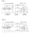
- FIG. 1 is a circuit diagram for normal operation of a battery pack associated with a form of embodiment of the present invention.
- FIG. 2 is a circuit diagram when abnormalities are detected in a battery pack associated with a form of embodiment of the present invention.
- FIG. 3 is an enlarged oblique view showing the output terminal section of a battery pack associated with a form of embodiment of the present invention.
- FIG. 4 is an exploded oblique view showing the entire battery pack of FIG. 3 .
- FIG. 5 is an equivalent circuit diagram showing the battery pack and electrical equipment of FIG. 1 .
- FIG. 6 is an equivalent circuit diagram showing the battery pack and electrical equipment of FIG. 2 .
- FIG. 7 is a cross-section view showing an example of the configuration of a contact switching section during normal operation.
- FIG. 8 is a cross-section view showing an example of the configuration of a contact switching section when abnormalities are detected.
- FIG. 9 is an oblique view showing a terminal section for a battery pack associated with a form of embodiment of the present invention.
- FIG. 10 is an exploded oblique view showing the terminal section for a battery pack of FIG. 9 .
- FIG. 11 is a plane view showing the terminal section for a battery pack of FIG. 9 .
- FIG. 12 is a lengthwise cross-section view showing the terminal section for a battery pack of FIG. 9 .
- FIG. 13 is a bottom view showing the terminal section for a battery pack of FIG. 9 .
- FIG. 14 is a lengthwise cross-section view showing the terminal section for a battery pack of FIG. 9 mounted on a battery.
- FIG. 15 is a circuit diagram showing an output terminal wiring layout for a related technology battery pack.
- FIG. 16 is a circuit diagram showing an output terminal wiring layout for a battery pack associated with a form of embodiment of the present invention.
- FIG. 17 is a circuit diagram showing an output terminal wiring layout for a battery pack associated with a form of embodiment of the present invention.
- FIGS. 1 and 2 are circuit diagrams of a battery pack associated with one form of embodiment of the present Invention, and FIGS. 3 and 4 are oblique views of the battery pack.
- the battery pack shown in these figures is provided with a rechargeable battery 4 and a protection device 3 to prevent events such as abnormal rechargeable battery 4 discharge.
- the protection device 3 is provided with a protection element 5 , a contact switching section 12 , and a detection device 17 .
- the protection device 3 is also provided with a first output terminal 6 A, a second output terminal 6 B, and a third output terminal 6 C. As shown in FIGS. 3 and 4 , the three output terminals 6 are disposed in a line with electrode surfaces exposed externally.
- each output terminal is arranged in a straight line from left to right in the order second output terminal 6 B, third output terminal 6 C, and first output terminal 6 A, it should be clear they are not limited to this arrangement. Disposition of each output terminal can be swapped, and optimal vertical, horizontal, skewed, triangular, or other terminal arrangements can be adopted.
- the positive electrode of the rechargeable battery 4 is connected to the first output terminal 6 A.
- One end of the protection element 5 and one end of the contact switching section 12 are connected to the negative electrode of the rechargeable battery 4 .
- the other end of the protection element 5 is connected to one end of the detection device 17 and the second output terminal 6 B.
- the other end of the detection device 17 is connected to the third output terminal 6 C.
- the third output terminal 6 C connects with the detection device 17 and identifies the type of the rechargeable battery 4 . Further, the third output terminal 6 C can also connect to a temperature sensor, such as a thermistor, in addition to, or in place of the detection device 17 , to detect rechargeable battery 4 temperature.
- a temperature sensor such as a thermistor
- the contact switching section 12 is configured with one end always fixed, and with the other switching end allowing switching when an abnormality is detected.
- the fixed end of the contact switching section 12 (node C in FIG. 1 ) is connected between the negative electrode of the rechargeable battery 4 and the protection element 5 .
- the switching end can switch between either the other end of the protection element 5 , node A in FIG. 1 , or between the detection device 17 and the third output terminal 6 C, node B in FIG. 2 .
- This contact switching section 12 switches its switching end to contact node A, which is the normal operating position, when there are no abnormalities or operation is normal, and switches its switching end to contact node B, which is the abnormal position, when an abnormality is detected.
- the circuit of FIG. 1 can be drawn as the equivalent circuit of FIG. 5
- the circuit of FIG. 2 can be drawn as the equivalent circuit of FIG. 6 .
- the protection element 5 When there are no abnormalities or operation is normal, the protection element 5 is short circuited because the contact switching section 12 connects nodes C and A, and the protection element 5 conducts negligible current. Consequently, as shown in the equivalent circuit of FIG. 5 , the first output terminal 6 A and the second output terminal 6 B are connected to the positive and negative electrodes respectively of the rechargeable battery 4 , and electrical power is supplied from the rechargeable battery 4 to electrical equipment connected with the battery pack. In addition, the third output terminal 6 C is connected to the negative electrode of the rechargeable battery 4 via the detection device 17 . Therefore, a prescribed voltage appears at the third output terminal 6 C. Since a voltage dividing resistor R 1 is connected in the electrical equipment between the first output terminal 6 A and the third output terminal 6 C, as shown in FIG. 1 , a voltage value is detected at the third output terminal 6 C which is the voltage at the rechargeable battery 4 terminals voltage divided by R 1 and the detection device 17 .
- the detection device 17 is used not only to identify the battery pack, but also to detect abnormal operation.
- the switching end of the contact switching section 12 switches from node A to node B. Consequently, node C and node B become connected, and the circuit configuration changes from the equivalent circuit of FIG. 5 to that of FIG. 6 .
- the third output terminal 6 C is connected to the negative electrode of the rechargeable battery 4 , which is the reference voltage, no voltage appears at that terminal.
- the electrical equipment can detect battery pack abnormality by detecting voltage at the third output terminal 6 C, which drops from the voltage divider value established by R 1 and detection device 17 , to zero.
- the second output terminal 6 B is connected to the negative electrode of the rechargeable battery 4 via the protection element 5 , current flow is reduced.
- the electrical equipment can transition to a prescribed abnormal operating mode at this time.
- the electrical equipment is provided with a control section 18 which monitors the third output terminal 6 C, and a display section 19 controlled by the control section 18 .
- the control section 18 and the display section 19 receive electrical power from the rechargeable battery 4 via the first output terminal 6 A and the second output terminal 6 B.
- the control section 18 judges the situation as normal.
- third output terminal 6 C voltage drops to zero as shown in FIG.
- the control section 18 judges battery pack conditions as abnormal, and issues instructions to transition to a specified abnormal mode of operation.
- abnormal mode operations actions are taken such as warning the user that a battery pack abnormality has occurred, protecting or saving data in mid-operation, switching to a low power operating mode, or switching to a spare battery,
- the electrical equipment is a portable telephone (cell-phone)
- the control section 18 detects abnormality, a message describing abnormal occurrence or a standby screen is displayed by the display section while operations are suspended and data is temporarily saved.
- the control section 18 can be configured as a gate array integrated circuit such as an FPGA or ASIC.
- a liquid crystal display or light emitting diode (LED) display can be used as the display section 19 .
- Power for abnormal mode operation is supplied from the rechargeable battery 4 via the protection element 5 . Since the amount of current supplied through the protection element 5 is limited, abnormal mode operations are those which can be executed with lower power than normal.
- the electrical equipment may use the alternate power source instead of, or in addition to the rechargeable battery 4 .
- electrical equipment can use an alternate power source such as an internally housed back-up battery, or a capacitor which is charged by the battery pack during normal operation and discharged during abnormal operation.
- the protection element 5 is a resistor or high temperature, high current protection element. Specifically, a component which detects temperature rise or current increase and limits current such as a PTC device can be used as the protection element 5 .
- a PTC (positive temperature coefficient) device is a composite material with positive slope resistance-temperature characteristics. A PTC device has the characteristic that resistance increases with temperature and effectively blocks current flow when temperature rise is detected.
- the contact switching section 12 also detects temperature rise and current increase. As described above, when abnormality is detected, the switching end switches to change electrical connection. When abnormality is not detected, the contact switching section 12 is connected in parallel with the protection element 5 , and when abnormality is detected, the contact switching section 12 is configured to connect the negative electrode of the rechargeable battery 4 and the third output terminal 6 C.
- Bimetal can be used for this type of contact switching section 12 . Bimetal is made up of two types of thin metal plates with different coefficients of expansion which are adhered together. When temperature changes, curvature of both metal plates changes according to the difference in expansion coefficients, and the bimetal plate becomes curved.
- invar 64% Fe,: 36% Ni
- bronze Cu, Sn
- a third metal with an intermediate coefficient of expansion can also be sandwiched between the two metals to smooth the change in curvature.
- FIGS. 7 and 8 An example of a contact switching section 12 configuration using bimetal is shown in FIGS. 7 and 8 . These figures are cross-section views showing exposed regions of the first output terminal 6 A, the third output terminal 6 C, and the second output terminal 6 B at the upper surface of the battery pack.
- FIG. 7 shows the contact switching section 12 prior to activation when no abnormality is detected
- FIG. 8 shows an example of a contact switching section 12 activated due to detection of an abnormality.
- the contact switching section 12 is provided with an arm 12 A activated by bimetal, and this arm 12 A is activated either directly or indirectly by bimetal.
- the contact switching section 12 of FIGS. 7 and 8 is provided with an arm 12 A and a pressure plate 12 B.
- the arm 12 A is a flexible plate of conductive material, and preferably a copper alloy can be used.
- the metal plate arm 12 A is configured to curve downward in its normal state.
- the pressure plate 12 B is made of bimetal, is disposed at the bottom surface of the arm 12 A, and pushes upward on the arm 12 A.
- the pressure plate 12 B normally has a convex shape as shown in FIG. 7 , but its ends spring upward into a concave shape during detection of an abnormality and pushes the arm 12 A against the upper surface as shown in FIG. 8 .
- the first output terminal 6 A is made of nickel sheet and connected to the positive electrode of the rechargeable battery 4 .
- the detection device 17 is connected between the third output terminal 6 C and the second output terminal 6 B, which are similarly made of nickel sheet.
- a base plate 11 made of copper alloy sheet and disposed below the output terminals is connected to the negative electrode of the rechargeable battery 4 .
- a silver alloy base plate contact 11 B and a PTC device, which is the protection element 5 are connected to the upper surface of the base plate 11 . The upper and lower surfaces of this PTC device form its contacts.
- insulating material 13 A, 13 B is disposed on the left and right of the PTC device. As shown in FIG.
- the bimetal pressure plate 12 B which rides on the upper surface of the PTC device, is supported by the insulating material 13 A, 13 B and is insulated from other materials.
- a copper alloy plate arm 12 A is provided with a movable contact 10 A projecting downward from the switching end of the arm 12 A, and a movable contact 10 B on the back of the arm 12 A slightly aft of the switching end. These contacts are both made opening surface silver.
- the contact switching section 12 can be assembled as a single unit with the output terminal section 6 D.
- the contact switching section 12 operates as follows.
- the third output terminal 6 C is connected to the second output terminal 6 B via the detection device 17 .
- electrical power is supplied to the electrical equipment from the rechargeable battery 4 of the battery pack, and the third output terminal 6 C is connected to the detection device 17 .
- the bimetal pressure plate 12 B curves, its ends spring upward as shown in FIG. 8 , and it flexibly presses the arm 12 A against the upper surface. Point A becomes disconnected, and the movable contact 10 B contacts the third output terminal 6 C at point B.
- the upper surface of the PTC device is connected to the second output terminal 6 B via the pressure plate 12 B and the arm 12 A.
- the detection device 17 is bypassed by upper surface connections of the arm 12 A, and the third output terminal 6 C is directly connected to the second output terminal 6 B.
- the second output terminal 6 B is connected via the PTC device to the negative electrode of the rechargeable battery 4 by the bottom surface of the arm. In this configuration, limited current is supplied to the electrical equipment via the PTC device, and the electrical equipment control section 18 detects abnormality and transitions to abnormal mode operation.
- the protection element 5 and the contact switching section 12 which detect temperature rise, are assembled in combination, and during abnormal conditions the contact switching section 12 switches connections while the high temperature, high current protection device limits current. Consequently, the temperature for bimetal and PTC activation is made approximately equal.
- the contact switching section 12 is not limited to the structure described above.
- the arm 12 A can be made of bimetal without using a pressure plate 12 B, and the arm itself can be configured to bend.
- the contact switching section 12 is configured as a single structure with the output terminal section 6 D.
- the molded resin region 21 becomes the external case 1 .
- the unassembled battery 7 which is the rechargeable battery 4
- the output terminal section 6 D is joined with the output terminal section 6 D to form a battery pack core, which is fixed in the molded resin region 21 by insertion molding.
- a battery pack with an external case formed as a plastic case is assembled by joining the protection device 3 and battery 7 as a battery pack core and Inserting the core in the external case.
- Battery pack assembly is not limited to this example, and a separately molded plastic external case can also be loaded with a battery pack core, made from an output terminal section joined to a battery.
- the contact switching section can be configured separately from the output terminal section and combined for assembly.
- voltage is detected at the third output terminal 6 C to judge normal or abnormal conditions, but the system may also be configured to detect current instead of voltage.
- the first output terminal was the positive electrode and the second output terminal was the negative electrode in the example described above, but the positive and negative electrodes may be swapped for a circuit configuration with the first output terminal as the positive electrode and the second output terminal as the negative electrode to obtain the same result.
- the contact switching section is also implemented with a simple structure using bimetal to switch contact. In this manner, required cost is reduced in the form of embodiment described above by implementing abnormality detection and over-current protection with a simple structure, and without using a complex over-current protection section made up of a plurality of electronic circuits. Furthermore, when an abnormality occurs, current is not completely cut-off as with a circuit breaker, partial current is sustained allowing abnormal mode operation, occurrence of the abnormality is immediately transmitted to the electrical equipment, and data loss due to instant power cut-off is avoided. In addition, recovery is achieved by automatic return to normal operation when the abnormal conditions cease to exist.
- the battery pack shown in FIGS. 3 and 4 is provided with alignment cut-outs 2 in the corner regions of the external case 1 to attach the battery pack solidly in position in the electrical equipment battery mounting section (not illustrated).
- alignment cut-outs 2 are provided at both sides of the front surface of the external case, which holds the output terminals 6 . Since a battery pack with alignment cut-outs 2 can mate in a fixed position on the electrical equipment battery mounting section, it can mount solidly on the electrical equipment without moving in position.
- the battery pack associated with a form of embodiment of the present invention does not necessarily have to provide alignment cut-outs in its external case. This is because the battery pack can mate with the electrical equipment battery mounting section to hold it in a fixed position.
- FIG. 9 an oblique view is shown in FIG. 9
- FIG. 10 an exploded oblique view is shown in FIG. 10
- a plane view is shown in FIG. 11
- a lengthwise cross-section view is shown in FIG. 12
- a bottom view is shown in FIG. 13
- a lengthwise cross-section view showing the protection device 3 attached to a battery 7 is shown in FIG. 14 .
- the protection device 3 shown in these figures is provided with a cover 15 for the output terminals 6 , a contact switching section 12 to switch contact when abnormality occurs, a protection element 5 to limit current and protect the rechargeable battery 4 when abnormality occurs, and a protection device base 16 .
- This protection device 3 is made by joining its cover 15 and base 16 and disposing safety elements 20 , such as the contact switching section 12 and protection element 5 , between the cover 15 and base 16 .
- the cover 15 and base 16 are joined together by fastening with screws or hooks etc., or by welding or bonding etc.
- the cover 15 and base 16 can be joined together with synthetic resin Including the protection device 3 molded as a single unit.
- the protection device 3 is electrically connected to the battery 7 , which makes up the rechargeable battery 4 .
- the battery pack part or all of the rechargeable battery 4 is inserted and fixed in the molded resin region 21 , and the protection device 3 is inserted and fixed in the molded resin region 21 with the output terminals 6 exposed externally.
- the protection device 3 is configured with insulating casing, and part or all of the cover 15 and base 16 are made of insulating material. Battery pack output terminals 6 are attached to the surface of the protection device 3 cover 15 , and the output terminals 6 are inserted and fixed in the molded resin region 21 via the protection device 3 .
- the first output terminal 6 A, the second output terminal 6 B, and the third output terminal 6 C, which make up the output terminals 6 are disposed adjacent to each other approximately in the same plane with approximately the same shape in an externally exposed fashion on the cover 15 .
- the cover is made of synthetic resin which forms a single piece with the output terminals.
- the protection device 3 can also be molded with synthetic resin as a single piece with the cover 15 and base 16 . In this manner, the protection device 3 is formed as a single unit containing protection elements in insulating casing and exposing battery pack output terminals at the surface.
- the protection element 5 which protects the rechargeable battery 4 from abnormal conditions, is disposed in an open region at the mating surface of the cover 15 and base 16 .
- the protection element 5 is connected between the rechargeable battery 4 and the output terminals 6 and shuts down rechargeable battery 4 output when abnormality occurs to prevent over-current.
- the protection element 5 can be housed in the protection device 3 to directly connect it with the output terminals 6 or dispose it in a position close to the output terminals 6 . Consequently, a separate protection circuit is not necessary, a circuit board and electronic components are not required, and additional space inside the battery pack does not need to be allocated to house those parts thereby contributing to size and cost reduction.
- the protection device 3 has a detection device 17 , which identifies the type of the rechargeable battery, directly attached to the surface of the output terminals 6 .
- a detection device 17 which identifies the type of the rechargeable battery, directly attached to the surface of the output terminals 6 .
- the front surfaces of the output terminals 6 are exposed externally as connection terminals for the electrical equipment, the backsides of the output terminals 6 are used for detection device 17 attachment, and the detection device 17 is directly fixed to the output terminals 6 by soldering or spot welding etc.
- protection device 3 space is efficiently used to allow a compact structure.
- wiring between the detection device 17 and the output terminals 6 is minimized, and omitting wiring and circuit boards contributes to cost and space reduction. Detailed description of each component follows.
- the cover 15 of the protection device 3 has output terminals 6 attached to its surface.
- the output terminals 6 are exposed outside the external case 1 , and connect with power supply terminals (not illustrated) on the electrical equipment.
- the output terminals 6 are provided with a first output terminal 6 A and second output terminal 6 B which connect with positive and negative power supply terminals, and with a third output terminal 6 C which Is a signal terminal.
- These output terminals 6 are each exposed externally as rectangular shapes of approximately the same size, they are disposed next to each other in the cover 15 , and they are formed as a single piece with the synthetic resin cover 15 .
- the output terminals 6 are disposed in approximately a straight line and in order from left to right, the first output terminal 6 A, the third output terminal 6 C, and the second output terminal 6 B, but it should be clear there is no limit to the above arrangement.
- the third output terminal 6 C which is the signal terminal, functions as an identification terminal to distinguish the type of the battery pack.
- Output terminals 6 of a related technology battery pack are provided with first and second output terminals 6 which connect with rechargeable battery positive and negative power supply terminals.
- a related technology battery pack which is provided with a terminal for signal detection has, for example as shown in FIG. 15 , the signal terminal short circuited to the negative output terminal.
- the detection device 17 is connected to the signal terminal as shown in FIG. 16 .
- the detection device 17 is specified corresponding to the characteristics and type of the battery pack rechargeable battery 4 .
- the detection device 17 as a resistor having resistance related to rechargeable battery 4 capacity, electrical equipment connected with the battery pack can distinguish the battery capacity of the battery pack. Since the electrical equipment can determine whether or not a suitable battery pack has been attached, the user can confirm if a suitable battery pack has been selected and attached even when a plurality of battery pack types are available. If a battery pack is determined to be of a different type, for example if a battery pack with a specified voltage not matching the electrical equipment is attached, error information can be displayed and power from the battery pack not accepted, or the user can be notified that the wrong battery pack has been attached via the display section 19 etc.
- the electrical equipment is a battery charger for charging the battery pack
- battery capacity can be determined by resistance detection via the third output terminal 6 C, and the battery pack can be charged in an optimal fashion.
- detection device 17 resistance is set to 75 K ⁇
- resistance is set to 85 K ⁇ .
- electrical equipment connected with the battery pack can acquire information concerning rechargeable battery 4 characteristics set by the detection device 17 and detected by voltage and current etc. detected at the signal terminal.
- battery pack authenticity can be determined based on the detection device 17 .
- a battery pack with equal terminal voltage but not recommended as an authentic battery pack in other words a battery pack with no detection device 17
- it is judged as not authentic by detecting the voltage at the third output terminal 6 C.
- the electrical equipment it is possible for the electrical equipment to judge battery pack authenticity and display an error message etc.
- problems such as power supply instability can result from connecting a poor quality battery pack which does not meet authentic specifications, such as a pirate battery pack, these problems can be avoided by distinguishing battery authenticity with certainty, and battery pack reliability can be improved.
- the detection device 17 can be a resistor or capacitor, and a chip resistor or IC chip can be used.
- a resistor R 2 and capacitor C 2 are connected in parallel between the second output terminal 6 B and the third output terminal 6 C.
- these components are fixed on the backside of the terminals bridging between the terminals in a conducting fashion. Consequently, battery identification is possible with minimum distance connection using no wires thereby reducing component count, conserving space, and lowering cost.
- the detection device 17 If an IC chip etc. is used as the detection device 17 , data communication between the battery pack and the electrical equipment can take place via the signal terminal, and more sophisticated battery pack identification is possible.
- the third output terminal 6 C which is the signal terminal, can also function as an abnormality detection terminal to detect rechargeable battery 4 abnormalities, in addition to having the function of battery pack type identification.
- the electrical equipment can be notified of an abnormal occurrence by establishing a change in voltage or current at the signal terminal when an abnormality is detected.
- the contact switching section 12 shown in FIG. 10 is a circuit breaker.
- the circuit breaker is configured with safety elements 20 disposed between the cover 15 and the base 16 , and is provided with a movable contact plate 12 D.
- the movable contact plate 12 D is a conducting metal plate which can flexibly deform, it has one end fixed at the second output terminal 6 B and the third output terminal 6 C, and it has contact metal 12 C fixed at its front end.
- the movable contact plate 12 D is in the ON state when the contact metal 12 C is touching a fixed contact 14 on a lead 8 attached to the base 16 , and can switch to the OFF state when it separates from the lead 8 .
- the movable contact plate 12 D is made of temperature distorting metal to deform with temperature by itself, or it can turn ON and OFF with temperature change via a separate temperature distorting metal material.
- the temperature distorting metal is bimetal or tri-metal, which are laminates of metals with different thermal coefficients of expansion. The temperature distorting metal deforms with temperature rise and the movable contact plate 12 D switches from the ON position to the OFF position.
- the temperature distorting metal of the circuit breaker detects battery temperature and switches the movable contact plate 12 D ON and OFF.
- the circuit breaker can also be configured to carry battery current in the temperature distorting metal, or a heat dependent resistor can be connected in series with the battery, the heat dependent resistor can be configured to heat the temperature distorting metal, and the circuit breaker can detect over-current and cut-off current flow.
- the movable contact plate can also be temperature distorting metal. Since the movable contact plate is also used as temperature distorting metal in this type of circuit breaker, the internal structure can be simplified.
- a circuit breaker is used in the contact switching section 12 of FIG. 10
- a PTC device, fuse, or protection circuit configured from an electronic circuit can also be used as a protection element 5 , or used in combination in the contact switching section 12 .
- the protection device 3 is provided with a protection element 5 which shuts down current to safely protect the battery when a battery abnormality occurs.
- a fuse or protection circuit configured from an electronic circuit can be used as the protection element 5 .
- material is housed in the base 16 which has electrical resistance that increases radically when temperature exceeds a set temperature and effectively shuts down current flow.
- a fuse detects over-current and cuts-off current flow.
- a protection element which melts open with excessive current is housed in the base 16 .
- a protection circuit which is an electronic circuit detects over-current, temperature, over-charge, or over-discharge and controls charging and discharging current.
- a protection circuit configured from an electronic circuit is implemented by housing necessary electronic components in the base 16 . Otherwise, a circuit breaker which detects temperature or over-current and cuts-off current flow can also be used in place of the protection element 5 . Since the contact switching section 12 , such as a circuit breaker, described above can also detect temperature or current increase, the contact switching section 12 and protection element 5 can be combined to detect abnormalities and protect the battery and circuitry. In the example of FIGS. 1 and 2 , a protection element 5 which detects temperature rise and a contact switching section 12 were combined to change connections with the contact switching section 12 when an abnormality occurred and also to limit current flow with a high temperature, high current protection device. Therefore, activation temperature for the bimetal and PTC device are made approximately the same.
- the protection device 3 shown in FIG. 14 has output terminals 6 fixed to the surface of the cover 15 , and the protection device 3 serves additionally as a terminal holder to fix the output terminals 6 in specified positions.
- the first output terminal 6 A is connected to the battery 7
- the third output terminal 6 C is connected to the second output terminal 6 B via the detection device 17
- the second output terminal 6 B is connected to the battery 7 via a safety element 20 disposed on the base 16 .
- the output terminals 6 are inserted and fixed in the plastic cover 15 .
- the output terminals 6 can also be attached to the cover 15 by means such as pins, screws, or pressure fitting etc.
- the protection device 3 Is also provided with alignment cavities 5 A to temporarily hold the battery pack core in proper alignment inside the mold when forming the molded resin region 21 .
- the base 16 of the figures is provided with a plurality of alignment cavities 5 A in both sides of its bottom surface.
- the alignment cavities 5 A are recessions provided in the bottom surface of the base 16 . Pins in the mold insert in the alignment cavities 5 A to temporarily hold the protection device 3 in proper position within the mold.
- a pair of leads 8 to connect to the battery 7 are attached to the cover 15 and base 16 .
- the pair of leads connects to the positive and negative electrodes of the battery 7 to connect the protection device 3 with the battery 7 .
- the leads 8 extend outside the cover 15 .
- One lead 8 is connected as a unit with the metal plate which forms the first output terminal 6 A.
- the other lead 8 connects with the second output terminal 6 B via the safety element 20 disposed on the base 16 .
- the leads fix to the protruding electrode 7 A and planar electrode 7 B of the battery 7 to connect the phosphors 3 with the battery 7 .
- the leads are welded and fixed on the battery 7 electrodes by a method such as resistive welding or laser welding etc.
- the battery pack core is assembled.
- a battery pack with the protection device 3 which has output terminals 6 attached, connected to the battery 7 , can connect the protection device 3 , output terminals 6 , and the battery 7 without using a circuit board. Consequently, in the battery pack of FIG. 14 , the protection device 3 is inserted and fixed in the molded resin region 21 , which is the external case 1 , without a circuit board.
- the protection element can also be attached to a circuit board and connected to the battery via the circuit board.
- the output terminals can also be attached to a terminal holder and fixed to a specified position in the external case.
- the type of the rechargeable battery housed in a battery pack described above can be distinguished, electrical equipment can accurately distinguish between a plurality of types of battery packs, a warning can be issued for attachment of a battery pack different from requirements, battery packs not meeting specifications can be excluded, charging can be performed that is most suitable for the battery pack, and the battery pack can be used in an optimal fashion. For example, there is no need to change battery pack shape to a special shape to fit connected electrical equipment, connection of a different type of battery pack with a shape that fits with the electrical equipment by coincidence can be avoided, and mistaken connection of battery packs can be effectively avoided.
- the signal terminal is used not only for rechargeable battery identification, but also for detection of battery abnormalities resulting in reduction in the number of terminals and contributing to battery pack size reduction.
Landscapes
- Engineering & Computer Science (AREA)
- Chemical & Material Sciences (AREA)
- Chemical Kinetics & Catalysis (AREA)
- Electrochemistry (AREA)
- General Chemical & Material Sciences (AREA)
- Power Engineering (AREA)
- Manufacturing & Machinery (AREA)
- Battery Mounting, Suspending (AREA)
- Secondary Cells (AREA)
- Connection Of Batteries Or Terminals (AREA)
Applications Claiming Priority (4)
| Application Number | Priority Date | Filing Date | Title |
|---|---|---|---|
| JP2003081065A JP3738257B2 (ja) | 2003-03-24 | 2003-03-24 | パック電池およびパック電池の異常検出方法 |
| JP81065/2003 | 2003-03-24 | ||
| JP2003120660A JP3789905B2 (ja) | 2003-04-24 | 2003-04-24 | パック電池 |
| JP120660/2003 | 2003-04-24 |
Publications (2)
| Publication Number | Publication Date |
|---|---|
| US20040189245A1 US20040189245A1 (en) | 2004-09-30 |
| US6924625B2 true US6924625B2 (en) | 2005-08-02 |
Family
ID=32179167
Family Applications (1)
| Application Number | Title | Priority Date | Filing Date |
|---|---|---|---|
| US10/803,954 Expired - Fee Related US6924625B2 (en) | 2003-03-24 | 2004-03-19 | Battery pack and method of detecting battery pack abnormalities |
Country Status (5)
| Country | Link |
|---|---|
| US (1) | US6924625B2 (ko) |
| KR (1) | KR100567956B1 (ko) |
| CN (1) | CN100389519C (ko) |
| DE (1) | DE102004013911A1 (ko) |
| GB (1) | GB2400759B (ko) |
Cited By (6)
| Publication number | Priority date | Publication date | Assignee | Title |
|---|---|---|---|---|
| US20050266302A1 (en) * | 2004-05-31 | 2005-12-01 | Kim Jun H | Secondary battery |
| US20100013492A1 (en) * | 2007-12-19 | 2010-01-21 | Kuen-Cheng Wang | Storage battery inspecting system |
| US20100060232A1 (en) * | 2008-09-08 | 2010-03-11 | Samuel Boyles | Battery charger |
| US20100181965A1 (en) * | 2009-01-16 | 2010-07-22 | Panasonic Electric Works Co., Ltd. | Battery charger and detection structure for detecting mounted compact electric apparatus |
| US20110121783A1 (en) * | 2008-09-08 | 2011-05-26 | Samuel Boyles | Battery charger |
| US20130200853A1 (en) * | 2012-02-02 | 2013-08-08 | Samsung Sdi Co., Ltd. | Electric tool with controller of battery pack and the control method thereof |
Families Citing this family (26)
| Publication number | Priority date | Publication date | Assignee | Title |
|---|---|---|---|---|
| US7336054B2 (en) | 1998-08-14 | 2008-02-26 | Milwaukee Electric Tool Corporation | Apparatus and method of activating a microcontroller |
| US7545147B2 (en) * | 2004-08-31 | 2009-06-09 | Eaglepicher Technologies, Llc | System and method for nondestructive testing of thermal batteries |
| JP3765544B1 (ja) * | 2004-11-26 | 2006-04-12 | 株式会社ソニー・コンピュータエンタテインメント | バッテリ、及び認証要求装置 |
| JP2006302693A (ja) * | 2005-04-21 | 2006-11-02 | Sony Corp | バッテリー |
| KR100786941B1 (ko) | 2005-05-10 | 2007-12-17 | 주식회사 엘지화학 | 이차전지 보호회로 및 이를 구비한 이차전지 |
| JP5111760B2 (ja) * | 2005-12-21 | 2013-01-09 | 三星エスディアイ株式会社 | 電池用保護素子及び電池 |
| DE102007020905B4 (de) * | 2007-04-26 | 2021-03-04 | Varta Microbattery Gmbh | Galvanisches Element mit Sicherungsmittel |
| DE102007029746A1 (de) * | 2007-06-27 | 2009-01-08 | Robert Bosch Gmbh | Wiederaufladbare Energieversorgungseinrichtung mit einer Identifizierungseinrichtung |
| DE102007030365B4 (de) * | 2007-06-29 | 2013-06-27 | Vb Autobatterie Gmbh & Co. Kgaa | Verfahren zur Klassifizierung einer Speicherbatterie und Klassifizierungseinheit |
| US7723961B2 (en) * | 2007-08-07 | 2010-05-25 | Honeywell International Inc. | MEMS based battery monitoring technical field |
| JP5000540B2 (ja) * | 2008-01-31 | 2012-08-15 | 新光電気工業株式会社 | スイッチング機能付配線基板 |
| JP5966247B2 (ja) * | 2011-03-01 | 2016-08-10 | ソニー株式会社 | 電池パック、蓄電システム、電子機器、電動車両、電力システムおよび制御システム |
| US8864476B2 (en) | 2011-08-31 | 2014-10-21 | Flow Control Llc. | Portable battery operated bilge pump |
| CN104519771B (zh) | 2012-03-20 | 2018-12-07 | 翠科有限公司 | 一种贩卖系统及方法 |
| JP2015532584A (ja) | 2012-10-19 | 2015-11-09 | トライコピアン・エルエルシー | 再充電可能バッテリを提供するためのシステムおよび方法 |
| CN104969408B (zh) * | 2013-03-21 | 2018-03-30 | 日立工机株式会社 | 电池包及电气设备 |
| WO2015027215A1 (en) | 2013-08-22 | 2015-02-26 | Tricopian, Llc | Standardized rechargeable battery cell |
| US9446680B2 (en) * | 2014-10-07 | 2016-09-20 | Ford Global Technologies, Llc | Method and apparatus for identifying battery pack types |
| GB2538933A (en) * | 2015-01-26 | 2016-12-07 | Bytec Healthcare Ltd | Battery docking system and battery module |
| GB2538932B (en) * | 2015-01-26 | 2021-12-29 | Bytec Healthcare Ltd | Battery module and casing |
| US11026311B2 (en) * | 2017-06-19 | 2021-06-01 | Abl Ip Holding Llc | Emergency lighting system with power rollback |
| WO2019037113A1 (zh) * | 2017-08-25 | 2019-02-28 | 深圳市云中飞网络科技有限公司 | 终端设备及其电池安全监控方法和监控系统 |
| CN108063486A (zh) * | 2018-01-23 | 2018-05-22 | 深圳可立克科技股份有限公司 | 适于多种电池充电的充电器及其充电方法、电能变换电路 |
| EP3811441B1 (en) * | 2018-06-22 | 2023-06-07 | Bourns, Inc. | Circuit breakers |
| JP7336264B2 (ja) * | 2019-05-29 | 2023-08-31 | 株式会社マキタ | バッテリパック |
| EP4022662A4 (en) | 2019-08-27 | 2023-10-25 | Bourns, Inc. | CONNECTOR WITH INTEGRATED THERMAL SHUT-OFF DEVICE FOR A BATTERY PACK |
Citations (5)
| Publication number | Priority date | Publication date | Assignee | Title |
|---|---|---|---|---|
| GB2050721A (en) | 1979-04-10 | 1981-01-07 | Burka V A | Battery charging apparatus |
| US6075343A (en) * | 1999-02-12 | 2000-06-13 | Quanta Computer Inc. | Rechargeable battery pack module |
| JP3085539B2 (ja) | 1989-04-21 | 2000-09-11 | モトローラ・インコーポレーテッド | バッテリ駆動の無線機 |
| JP2000315483A (ja) | 1999-03-02 | 2000-11-14 | Kyocera Corp | バッテリー構造及びその製造方法 |
| US6498459B1 (en) * | 1999-01-26 | 2002-12-24 | Fujitsu Limited | Electronic equipment and battery unit |
Family Cites Families (2)
| Publication number | Priority date | Publication date | Assignee | Title |
|---|---|---|---|---|
| CN2241409Y (zh) * | 1996-01-17 | 1996-11-27 | 罗之洪 | 锂电池充电器 |
| EP0931701B1 (en) * | 1998-01-13 | 2003-12-10 | Delphi Automotive Systems Deutschland GmbH | Battery disconnection system |
-
2004
- 2004-03-19 GB GB0406267A patent/GB2400759B/en not_active Expired - Fee Related
- 2004-03-19 KR KR1020040018870A patent/KR100567956B1/ko not_active IP Right Cessation
- 2004-03-19 US US10/803,954 patent/US6924625B2/en not_active Expired - Fee Related
- 2004-03-19 CN CNB2004100301819A patent/CN100389519C/zh not_active Expired - Fee Related
- 2004-03-22 DE DE102004013911A patent/DE102004013911A1/de not_active Withdrawn
Patent Citations (5)
| Publication number | Priority date | Publication date | Assignee | Title |
|---|---|---|---|---|
| GB2050721A (en) | 1979-04-10 | 1981-01-07 | Burka V A | Battery charging apparatus |
| JP3085539B2 (ja) | 1989-04-21 | 2000-09-11 | モトローラ・インコーポレーテッド | バッテリ駆動の無線機 |
| US6498459B1 (en) * | 1999-01-26 | 2002-12-24 | Fujitsu Limited | Electronic equipment and battery unit |
| US6075343A (en) * | 1999-02-12 | 2000-06-13 | Quanta Computer Inc. | Rechargeable battery pack module |
| JP2000315483A (ja) | 1999-03-02 | 2000-11-14 | Kyocera Corp | バッテリー構造及びその製造方法 |
Cited By (12)
| Publication number | Priority date | Publication date | Assignee | Title |
|---|---|---|---|---|
| US20050266302A1 (en) * | 2004-05-31 | 2005-12-01 | Kim Jun H | Secondary battery |
| US7462416B2 (en) * | 2004-05-31 | 2008-12-09 | Samsung Sdi Co., Ltd. | Secondary battery |
| US20100013492A1 (en) * | 2007-12-19 | 2010-01-21 | Kuen-Cheng Wang | Storage battery inspecting system |
| US8174275B2 (en) * | 2007-12-19 | 2012-05-08 | Kuen-Cheng Wang | Storage battery inspecting system |
| US20100060232A1 (en) * | 2008-09-08 | 2010-03-11 | Samuel Boyles | Battery charger |
| US20110121783A1 (en) * | 2008-09-08 | 2011-05-26 | Samuel Boyles | Battery charger |
| US8378624B2 (en) | 2008-09-08 | 2013-02-19 | Techtronic Power Tools Technology Limited | Battery charger |
| US8441230B2 (en) | 2008-09-08 | 2013-05-14 | Techtronic Power Tools Technology Limited | Battery charger |
| US20100181965A1 (en) * | 2009-01-16 | 2010-07-22 | Panasonic Electric Works Co., Ltd. | Battery charger and detection structure for detecting mounted compact electric apparatus |
| US8242744B2 (en) * | 2009-01-16 | 2012-08-14 | Panasonic Corporation | Battery charger and detection structure for detecting mounted compact electric apparatus |
| US20130200853A1 (en) * | 2012-02-02 | 2013-08-08 | Samsung Sdi Co., Ltd. | Electric tool with controller of battery pack and the control method thereof |
| US9054537B2 (en) * | 2012-02-02 | 2015-06-09 | Samsung Sdi Co., Ltd. | Electric tool with controller of battery pack and the control method thereof |
Also Published As
| Publication number | Publication date |
|---|---|
| GB2400759B (en) | 2005-04-27 |
| CN1532989A (zh) | 2004-09-29 |
| CN100389519C (zh) | 2008-05-21 |
| DE102004013911A1 (de) | 2004-11-04 |
| KR20040084667A (ko) | 2004-10-06 |
| GB2400759A (en) | 2004-10-20 |
| GB0406267D0 (en) | 2004-04-21 |
| KR100567956B1 (ko) | 2006-04-05 |
| US20040189245A1 (en) | 2004-09-30 |
Similar Documents
| Publication | Publication Date | Title |
|---|---|---|
| US6924625B2 (en) | Battery pack and method of detecting battery pack abnormalities | |
| US6686722B2 (en) | Battery pack containing a circuit breaker | |
| US9246199B2 (en) | Battery pack | |
| US5800937A (en) | Current interrupt device for secondary batteries | |
| US5585710A (en) | Secondary battery device with spacer for thermistors and terminals and charging apparatus therefor | |
| EP1946394B1 (en) | No-welding type battery pack | |
| KR100760784B1 (ko) | 이차 전지용 보호회로모듈 및 이를 이용한 전지 팩 | |
| CA2592475C (en) | Sensing board assembly for secondary battery module | |
| JP3572793B2 (ja) | 電池パックおよび該電池パックの製造方法 | |
| EP3978196A1 (en) | Battery pack and electric device | |
| US6346796B1 (en) | Thermal shut-off device and battery pack | |
| KR102308633B1 (ko) | 전지 모듈 | |
| EP2413400A2 (en) | Secondary battery | |
| JP2014123553A (ja) | バッテリーパック | |
| KR101397027B1 (ko) | 배터리 팩 | |
| KR20170101604A (ko) | 배터리 팩 | |
| CN112542870A (zh) | 电子设备 | |
| JP4815151B2 (ja) | 感熱保護スイッチ装置及び電池パック | |
| JP4228089B2 (ja) | 過電流検知機構およびそれを用いた電子閃光装置 | |
| JP3658877B2 (ja) | バッテリーパック | |
| KR20160106325A (ko) | 이차 전지 | |
| JP3789905B2 (ja) | パック電池 | |
| JP7272430B2 (ja) | 電池パック及び電気機器 | |
| JPH11346443A (ja) | 蓄電装置用組電池制御装置 | |
| JP3738257B2 (ja) | パック電池およびパック電池の異常検出方法 |
Legal Events
| Date | Code | Title | Description |
|---|---|---|---|
| AS | Assignment |
Owner name: SANYO ELECTRIC CO., LTD., JAPAN Free format text: ASSIGNMENT OF ASSIGNORS INTEREST;ASSIGNORS:TERAOKA, HIROKI;YAMAZOE, TAKAMASA;NAKA, MASATSUGU;AND OTHERS;REEL/FRAME:015120/0921 Effective date: 20040309 |
|
| FEPP | Fee payment procedure |
Free format text: PAYOR NUMBER ASSIGNED (ORIGINAL EVENT CODE: ASPN); ENTITY STATUS OF PATENT OWNER: LARGE ENTITY |
|
| FPAY | Fee payment |
Year of fee payment: 4 |
|
| REMI | Maintenance fee reminder mailed | ||
| LAPS | Lapse for failure to pay maintenance fees | ||
| STCH | Information on status: patent discontinuation |
Free format text: PATENT EXPIRED DUE TO NONPAYMENT OF MAINTENANCE FEES UNDER 37 CFR 1.362 |
|
| FP | Lapsed due to failure to pay maintenance fee |
Effective date: 20130802 |