US6864653B2 - Equipment fan - Google Patents
Equipment fan Download PDFInfo
- Publication number
- US6864653B2 US6864653B2 US10/262,400 US26240002A US6864653B2 US 6864653 B2 US6864653 B2 US 6864653B2 US 26240002 A US26240002 A US 26240002A US 6864653 B2 US6864653 B2 US 6864653B2
- Authority
- US
- United States
- Prior art keywords
- motor
- signal
- equipment fan
- conveyed
- control line
- Prior art date
- Legal status (The legal status is an assumption and is not a legal conclusion. Google has not performed a legal analysis and makes no representation as to the accuracy of the status listed.)
- Expired - Fee Related
Links
Images


Classifications
-
- F—MECHANICAL ENGINEERING; LIGHTING; HEATING; WEAPONS; BLASTING
- F04—POSITIVE - DISPLACEMENT MACHINES FOR LIQUIDS; PUMPS FOR LIQUIDS OR ELASTIC FLUIDS
- F04D—NON-POSITIVE-DISPLACEMENT PUMPS
- F04D25/00—Pumping installations or systems
- F04D25/02—Units comprising pumps and their driving means
- F04D25/06—Units comprising pumps and their driving means the pump being electrically driven
- F04D25/0606—Units comprising pumps and their driving means the pump being electrically driven the electric motor being specially adapted for integration in the pump
- F04D25/0613—Units comprising pumps and their driving means the pump being electrically driven the electric motor being specially adapted for integration in the pump the electric motor being of the inside-out type, i.e. the rotor is arranged radially outside a central stator
-
- F—MECHANICAL ENGINEERING; LIGHTING; HEATING; WEAPONS; BLASTING
- F04—POSITIVE - DISPLACEMENT MACHINES FOR LIQUIDS; PUMPS FOR LIQUIDS OR ELASTIC FLUIDS
- F04D—NON-POSITIVE-DISPLACEMENT PUMPS
- F04D29/00—Details, component parts, or accessories
- F04D29/60—Mounting; Assembling; Disassembling
- F04D29/601—Mounting; Assembling; Disassembling specially adapted for elastic fluid pumps
-
- Y—GENERAL TAGGING OF NEW TECHNOLOGICAL DEVELOPMENTS; GENERAL TAGGING OF CROSS-SECTIONAL TECHNOLOGIES SPANNING OVER SEVERAL SECTIONS OF THE IPC; TECHNICAL SUBJECTS COVERED BY FORMER USPC CROSS-REFERENCE ART COLLECTIONS [XRACs] AND DIGESTS
- Y10—TECHNICAL SUBJECTS COVERED BY FORMER USPC
- Y10S—TECHNICAL SUBJECTS COVERED BY FORMER USPC CROSS-REFERENCE ART COLLECTIONS [XRACs] AND DIGESTS
- Y10S388/00—Electricity: motor control systems
- Y10S388/90—Specific system operational feature
- Y10S388/903—Protective, e.g. voltage or current limit
Definitions
- the invention concerns, inter alia, an equipment fan having a fan wheel that is driven by an external-rotor motor whose internal stator is mounted on a hub.
- the invention preferably concerns a fan of this kind that can communicate with an external control device via a control line (“bus”).
- Equipment fans are often installed in inaccessible locations where subsequent replacement of the fan, e.g. for a repair, is very difficult. This applies in particular to land and water vehicles and aircraft.
- this object is achieved by providing a housing containing non-wearing components, which releasably engages a replaceable module including an external rotor, fan wheel, a hub, an internal stator mounted on the hub, and at least one strut connecting the hub to a cylindrical casing.
- a replaceable module including an external rotor, fan wheel, a hub, an internal stator mounted on the hub, and at least one strut connecting the hub to a cylindrical casing.
- the housing can be mounted on an object that is to be ventilated, since it usually contains only mechanical parts that are not subject to wear.
- the component having the fan wheel, external-rotor motor, and casing part on the other hand, can easily be detached from said housing as necessary, and repaired or replaced with a new component of identical type.
- An exchange of this kind can be made in a very short period of time, so that damage due to failure of a fan does not result in extended downtime of the equipment being cooled by it.
- Another manner of achieving the stated object is to equip the motor with at least one signal line, through which control signals can be fed from outside to the motor, and through which a fault signal can be fed back from the motor to the outside, so that something can be done about the fault state. It enables rapid fault detection, and thus efficient replacement of a defective fan once a fault has been detected.
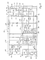
- FIG. 1 is an enlarged section through the right half of a first exemplary embodiment of a fan according to the invention
- FIG. 2 is a plan view, viewed in the direction of arrow II of FIG. 1 ;
- FIG. 3 is a side view of housing part 110 of FIG. 4 , viewed in the direction of arrow III of FIG. 4 ;
- FIG. 4 is a plan view of housing part 110 , viewed in the direction of arrow IV of FIG. 5 ;
- FIG. 5 is a side view of housing part 110 , viewed in the direction of arrow V of FIG. 4 ;
- FIG. 6 is a side view of the complete fan, viewed in the direction of arrow VI of FIG. 7 ;
- FIG. 7 is a plan view of the complete fan, viewed in the direction of arrow VII of FIG. 6 ;
- FIG. 8 is a side view of the complete fan, viewed in the direction of arrow VIII of FIG. 7 ;
- FIG. 9 is a side view of the complete fan, viewed in the direction of arrow IX of FIG. 7 ;
- FIG. 10 is a block diagram of a preferred circuit for remote control of a fan according to the invention via a control line (bus);
- FIG. 11 is a circuit diagram similar to FIG. 10 , with further details;
- FIG. 12 is a plan view of an equipment fan 320 according to a second exemplary embodiment of the invention, viewed in the direction of an arrow XII of FIG. 13 ;
- FIG. 13 is a side view, viewed in the direction of arrow XIII of FIG. 12 ;
- FIG. 14 is a plan view, viewed in the direction of arrow XIV of FIG. 13 ;
- FIG. 15 is a side view, depicted partly in section, which depicts the routing of the electrical connecting lines.
- FIG. 16 shows a preferred exemplary embodiment of apparatus 150 of FIG. 11 .
- FIG. 1 shows a greatly magnified section through the right half of an external-rotor motor 20 , the left half being essentially mirror-symmetrical thereto. To save drawing space, fan blade 46 and strut 74 are shown broken away.
- the motor has a hub 22 , made of a suitable plastic, that is configured integrally with a bearing support tube 24 in which an upper ball bearing 26 , a spacer 28 for the outer races, and a lower ball bearing 30 are arranged, which ball bearings support central shaft 32 of an external rotor 34 .
- the inner races of ball bearings 26 , 30 are braced against one another by a compression spring 36 that is arranged between the inner race of ball bearing 26 and a rotor part 38 .
- a Hall IC 50 is arranged on a circuit board 52 that carries electronic components for controlling motor 20 and for fault reporting. Hall IC 50 controls the current in motor 20 and serves as the sensor for its rotation speed.
- Central shaft 32 has, at its lower end, an annular groove 54 into which a holding part 56 , which is immobilized by means of a leaf spring 58 in bearing support tube 24 , resiliently engages.
- An internal stator 60 is mounted on the outer side of bearing support tube 24 .
- the stator has a lamination stack 62 in which a winding 68 is mounted by means of a coil carrier 64 , 66 .
- One terminal 70 of winding 68 is depicted. It is soldered to a pin 72 that is mounted in coil former 66 .
- Hub 22 is configured integrally with struts 74 which join hub 22 to a substantially cylindrical casing part 76 that surrounds fan blades 46 radially with a spacing (cf. FIG. 2 ).
- Struts 74 form a protective lattice that is depicted in FIGS. 2 and 7 and that also serves as a grasping aid for inserting motor 20 into a housing ( FIGS. 3 through 5 ) or removing it therefrom.
- FIG. 2 shows a plan view in the direction of arrow II of FIG. 1 . It is evident that six struts 74 are mounted on hub 22 , and join hub 22 to casing part 76 . Hub 22 , struts 74 , and casing part 76 are configured as an integral plastic part. Approximately at their midpoints, struts 74 are joined to one another by an annular strut 80 on which are applied an arrow 82 for the opening direction and an arrow 84 for the closing direction, as well as corresponding labels (OPEN, CLOSE).
- annular strut 80 on which are applied an arrow 82 for the opening direction and an arrow 84 for the closing direction, as well as corresponding labels (OPEN, CLOSE).
- Three connecting lines 86 , 88 (+ and ⁇ ) and 90 (control line) are soldered on in the region of hub 22 , and guided from there via a T-shaped clamp part 92 on the outer side of casing part 76 and a further clamping part 94 , also on the outer side of casing part 76 , to a connector plug 96 . Also located on the outer side of casing part 76 are four radially protruding pegs 98 which serve as snap-lock pegs and are here arranged at equal spacings of 90 degrees.
- the module depicted in FIGS. 1 and 2 made up of external-rotor motor 20 , fan blades 46 , and tubular casing 76 , is labeled 100 . It constitutes a replaceable module which, in the event of a fault, can be quickly replaced as a complete unit with no need to remove the fan housing for that purpose.
- FIG. 4 is a plan view of the open side of a fan housing 110 .
- the latter has at its bottom a protective lattice 112 that is configured integrally with housing 110 , and it has a substantially cylindrical opening 114 for receiving the cylindrical casing part 76 (FIG. 2 ).
- the contour of housing 110 is substantially square, e.g. having the standard dimensions 80 ⁇ 80 mm, but a thin-walled casing part 116 in which opening 114 is configured protrudes locally beyond this square contour. Openings 118 A, 118 B, 118 C, 118 D for the reception of pegs 98 ( FIG. 2 ) are provided in these protruding parts 116 A through 116 D.
- FIG. 3 depicts opening 118 A which is at the right side in FIG. 4 , and which transitions laterally into a latch opening 120 A that has on the one side a resilient latch tongue 122 A and on the other side a resilient latch tongue 124 A.
- FIG. 5 depicts opening 118 B that is at the bottom in FIG. 4 . It transitions laterally into a latch opening 120 B that has on the one side a resilient latch tongue 122 B and on the other side a resilient latch tongue 124 B.
- the other openings 118 C and 118 D are identical in configuration to opening 118 B, and the reference characters used for them are therefore identical, but have the letters C and D, respectively, added.
- cylindrical opening 114 has a radial enlargement 126 that extends over an angle of approximately 20 degrees.
- the cover of this enlargement is labeled 130 and is depicted in FIG. 3 .
- Latching members 132 for the mounting of plug 96 are located next to this cover (FIG. 2 ).
- Housing 110 has, at its corners, holes 136 for permanent mounting of this part onto a component that is to be cooled, e.g. a transmitter device; and it has two projecting pegs 138 for precisely fitted retention.
- Housing 110 is permanently installed on the part that is to be cooled. Module 100 ( FIG. 2 ) can then be inserted, after installation, into housing 110 and removed therefrom again if necessary, e.g. for repair.
- FIGS. 6 through 9 show the fan in its complete state and at approximately actual size.
- Module 100 is inserted into housing 110 and latched therein. This is done by pushing pegs 98 axially into openings 118 A- 118 D and then rotating module 100 a few degrees clockwise in the direction of arrow 84 (CLOSE). Pegs 98 thus snap into latch openings 120 A- 120 D, as shown clearly by FIGS. 6 , 8 , and 9 . Plug 96 is then snapped onto latching members 132 , as depicted in FIGS. 6 through 9 .
- module 100 is rotated a few degrees counterclockwise in the direction of arrow 82 , and then pulled axially out of housing 110 .
- a mark 122 is provided on casing part 76 and a mark 124 on casing part 116 C, and marks 122 , 124 point toward one another when module 100 is correctly latched. This permits easy visual inspection at the acceptance check.
- the openings between radial struts 74 and annular strut 80 are configured so that a person's fingers can be introduced into these openings and the protective lattice can be used as a grasping aid.
- protective lattice 112 depicted in FIG. 4 is arranged on one side of the complete fan, and protective lattice 74 , 80 is arranged on the other side of the fan, so that the latter has a protective lattice on both sides, the two protective lattices preferably being made of plastic.
- Protective lattice 112 is configured integrally with housing 110 , and protective lattice 74 , 80 integrally with tubular casing 76 and hub 22 .
- FIG. 10 shows an associated circuit.
- Motor 20 is depicted schematically on the right. It generates, by means of an apparatus 150 , i.e. tacho generator, a signal that corresponds to the actual rotation speed n ist , which is applied to a rotation speed controller 152 .
- Motor 20 is connected, in series with an output stage 154 , between lines 86 (+) and 88 (ground).
- output stage 154 is depicted symbolically as an npn transistor. In FIG. 11 , it is constituted by the two transistors 224 , 226 .
- Motor 20 is controlled by a control device 156 that serves in general to make available an actuating signal for motor 20 and to evaluate a fault signal from motor 20 .
- Control device 156 can supply a PWM (Pulse Width Modulation) signal or a DC voltage control signal as the actuating signal.
- PWM Pulse Width Modulation
- a DC voltage signal or a PWM signal 164 , that is delivered by control device 156 via control line 90 to motor 20 , converted there by a filter 158 into a DC voltage on a line 159 , and conveyed to rotation speed controller 152 as target value n soll .
- control can also be accomplished by means of a DC voltage that is conveyed to input 90 and can have values, for example, between 2 and 7 V.
- DC voltage n soll on line 159 increases as the pulse duty factor pwm of PWM signal 164 rises. The following conditions apply:
- connection 90 ′ from control device 156 to control line 90 is interrupted, rotation speed controller 152 would continuously receive a signal that would correspond to a PWM signal 164 having a pulse duty ratio of 100%, and motor 20 would run at maximum speed.
- a switching member 160 is provided that blocks output stage 154 in such a case, so that motor 20 receives no current and is shut off.
- a pulse duty factor >95% that is conveyed to control line 90 , and is also interpreted as a shutoff signal.
- terminal 86 is connected to the positive pole of the vehicle battery (not depicted). Terminal 86 is connected to a filter 166 for EMI (electro-magnetic interference) protection, and a diode 168 is provided for protection against incorrect connection to the battery. Also provided is a capacitor 170 that supplies motor 20 with reactive power.
- EMI electro-magnetic interference
- a stabilized voltage of e.g. +7.7 V is generated on line 174 by way of an internal constant-voltage source 172 , and is filtered by a capacitor 176 .
- Hall IC 50 which is controlled by permanent-magnet rotor 42 ( FIG. 1 ) and in turn controls output stage 154 via a connection 177 as a function of the position of said rotor, is connected to line 174 .
- a PTC (Positive Temperature Coefficient)resistor 180 whose output signal is conveyed via a line 182 to rotation speed controller 152 and controls the latter to a rotation speed of zero if the temperature of motor 20 /output stage 154 exceeds a value that is critical for all components, e.g. 115 degrees C., is provided in thermal communication with motor 20 and output stage 154 (or with the two transistors 224 , 226 in FIG. 11 ).
- a measuring resistor 184 Provided in the connection from output stage 154 to ground 88 is a measuring resistor 184 at which there occurs, during operation, a voltage which is dependent on the current i of motor 20 and is conveyed to a control member 186 .
- control member 186 then generates at an output 188 a signal which blocks output stage 154 for e.g. 13 seconds, and it generates at an output 190 a signal which is conveyed to an npn transistor 192 and makes the latter conductive.
- the emitter of transistor 192 is connected to ground 88 , and its collector to control line 90 ; i.e. when transistor 192 is conductive, control line 90 acquires approximately the potential of ground 88 .
- line 90 , 90 ′ is connected via a resistor 194 to the collector of an npn transistor 196 whose emitter is connected to ground 88 and to whose base the depicted PWM signal 164 is conveyed during operation.
- control line 90 When control line 90 is connected through transistor 192 to ground 88 , the effect is the same as if PWM signal 164 had a pulse duty ratio of 0%, and motor 20 is shut off. The same is true when a DC control voltage conveyed to input 90 assumes a value of zero.
- the collector of transistor 196 is connected via a resistor 198 to a node 200 , and the latter is connected to ground 88 via a resistor 202 and a capacitor 204 connected in parallel therewith.
- capacitor 204 becomes charged by the pulses of PWM signal 164 (for which see FIG. 11 ). The result is to produce a non-zero positive potential at node 200 . If, however, transistor 192 becomes conductive because motor current i is continuously too high, the potential of node 200 is then reduced, and a FAULT signal is produced as a result.
- PWM pulses 164 thus travel via control line 90 to rotation speed controller 152 ; and in the event of malfunctions, the fact that transistor 192 becomes conductive allows a fault signal to travel in the opposite direction from motor 20 to control device 156 .
- control member 208 which, when it responds, limits current i in output stage 154 to a defined value.
- Control member 186 is deactivated during starting, i.e. only starting current limiter 208 is active at that time.
- Line 188 is connected to the output of controller 152 , to the output of current limiter 208 , and to a diode member 209 . If controller 152 , control member 186 , or current limiter 208 generates a low potential at its output, diode member 209 then becomes conductive, reduces the voltage on line 177 , and thereby blocks output stage 154 completely or partially, so that either motor 20 receives zero current or (during starting) motor current i is limited.
- the target rotation speed of motor 20 is defined by means of a DC voltage (in this case 2-7 V) at input 90 or by means of pulse duty ratio pwm of PWM signal 164 . As long as the latter is less than 10%, motor 20 is stationary. In the range from 30 to 85%, the rotation speed increases. At a pulse duty ratio above 95%, the motor is switched off by way of switching member 160 , as already described.
- motor current i is limited by control member 208 to a defined maximum value, by the fact that diode member 209 correspondingly reduces the control signal for output stage 154 if starting current i becomes too high.
- control member 186 The periodic signal generated in this context by control member 186 is also conveyed via line 190 to npn transistor 192 , and causes the latter to switch on and off periodically. As a result, the potential at point 90 also changes periodically and is transferred via control line 90 ′ to control device 156 , where it generates the FAULT signal already described.
- FIG. 11 shows a brushless motor 20 having two stator winding phases 220 , 222 that are each connected in series with a power transistor 224 and 226 , respectively. For commutation, these are controlled in the usual way via their bases by Hall IC 50 (FIG. 10 ); this is not depicted in FIG. 11 .
- the base of transistor 224 is connected to the anode of a diode 228 , and that of transistor 226 to the anode of a diode 230 .
- the cathodes of diodes 228 , 230 are connected to a line 232 .
- Line 232 is connected to the collectors of two npn transistors 234 , 236 whose emitters are connected to ground 88 .
- transistors 234 , 236 When one of transistors 234 , 236 becomes conductive, a connection is created from the base of transistors 224 , 226 to ground, so that these transistors are blocked and motor 20 no longer receives current. If one of transistors 234 , 236 becomes only partially conductive, it then reduces the base current of transistors 224 , 226 so that motor current i correspondingly decreases. This occurs in the context of current limiting, principally when motor 20 is started.
- the emitters of transistors 224 , 226 are connected to ground 88 via a node 240 and measuring resistor 184 .
- the potential at node 240 is conveyed via a resistor 242 to the base of transistor 236 , so that the latter acts as a current limiter: as the voltage at resistor 184 increases, transistor 236 becomes increasingly conductive and thereby limits motor current i, for example to a maximum value of approximately 0.5 A at startup.
- the potential at node 240 is also conveyed to the positive input of an operational amplifier 244 , whose negative input is connected to a node 246 that is connected via a resistor 248 to ground 88 and via PTC resistor 180 and a resistor 250 to line 174 .
- Output 252 of operational amplifier 244 is connected via a capacitor 254 (e.g. 2.2 uF) to the positive input, via a resistor 256 (e.g. 100 kOhm) to node 246 , via a resistor 258 to the base of transistor 234 , via a capacitor 260 (e.g. 1 nF) to ground 88 , and via a resistor 262 to the base of transistor 192 .
- the base of transistor 234 is also connected via a resistor 264 to ground 88 .
- operational amplifier 244 Once operational amplifier 244 has switched over, it remains in that state for approximately 13 seconds because of the effect of capacitor 254 and then switches back into the state in which its output is low, so that transistors 192 and 234 are again blocked and motor 20 once again receives current. If the latter is still jammed, it is switched on for approx. two seconds and, if it does not start, is again made currentless for 13 seconds.
- Rotation speed controller 152 operates by comparing signals n ist and n soll . It has for that purpose an operational amplifier 152 K to which these signals are conveyed. If the rotation speed of motor 20 is too high, output 270 of operational amplifier 152 K then becomes high, and that signal is transferred via a resistor 272 to the base of transistor 236 , makes it conductive, and thereby influences transistors 224 , 226 so that motor current i (and thus the rotation speed of motor 20 ) decreases.
- Control line 90 is connected via a resistor 276 to line 174 and via a resistor 278 to a node 280 that is connected via a capacitor 282 to ground 88 and via a resistor 284 to the negative input of operational amplifier 152 K. That negative input is also connected via a resistor 286 to ground.
- Control line 90 is connected via a resistor 290 to the base of a pnp transistor 292 whose emitter, like the emitter of a pnp transistor 294 , is connected to line 174 .
- the collector of transistor 292 is connected via a resistor 296 to ground 88 , and via a capacitor 298 to its base. That base is also connected via a resistor 300 to the collector of transistor 294 , which is connected via a resistor 302 to the base of transistor 236 .
- transistor 294 When transistor 294 is conductive, it conveys a base current to transistor 236 and thereby blocks transistors 224 , 226 so that motor 20 receives no current.
- capacitor 282 is continuously discharged by the PWM pulses to a sufficient extent that transistor 292 is kept conductive by the potential on control line 90 and consequently blocks transistor 294 .
- capacitor 282 is charged to a higher voltage that is determined by resistors 276 , 278 , 284 , 286 ; as a result, transistor 292 is blocked, and transistor 294 becomes conductive and shuts off motor 20 in the manner described.
- control line 90 ′ ( FIG. 10 ) therefore causes motor 20 to come to a stop, whereas without circuit 160 it would run at maximum speed.
- control line 90 signals which control motor 20 (PWM signals 164 or a control DC voltage) in the direction toward motor 20 , and a fault signal (if motor 20 is rotating too slowly or is being prevented from rotating) in the opposite direction.
- FIGS. 12 through 15 show a second exemplary embodiment of an equipment fan 220 according to the present invention, which here is very small and has an outside diameter of approx. 4 cm.
- a common reference scale of 1 cm is indicated by way of example in order to illustrate typical size relationships.
- equipment fan 320 is assembled from two parts, namely an outer housing 322 which is equipped externally with a flange 324 that is configured integrally with a protective lattice 326 , and which has a substantially cylindrical opening 328 into which the actual fan 330 is inserted and locked.
- Fan 330 has a hub 332 that is connected via three struts 334 to a tubular outer part 336 whose outer side 338 fits with a sliding fit into opening 328 .
- two radially projecting pegs 340 are provided on outer side 328 with a 180-degree spacing, of which only one is depicted (in FIG. 13 ); provided in outer housing 322 to receive them are two guide openings 342 which in plan view (as in FIG. 13 ) are approximately L-shaped, i.e. proceeding from a lateral orifice, this opening extends first axially and then radially in a portion 344 that tapers toward its end into a latch opening into which (as shown in FIG. 13 ) peg 340 can be snap-locked.
- a wall portion 346 can yield elastically upon snap-locking or unsnapping. This solution is obviously simpler than the one shown in FIGS. 1 through 9 .
- Fan 330 has five fan blades 348 that are mounted on an external rotor 360 .
- Three lines 364 , 366 , 368 are provided for electrical connection of internal stator 362 ; they lead in this case to an electronic system (not depicted) outside fan part 330 , since with such a small equipment fan the electronics would not have enough room in fan 330 itself.
- lines 364 , 366 , 368 are guided around two holding parts 370 , 372 (on the outer side of tube 338 ) to a plug 374 .
- a label is designated 376 .
- outer housing 322 is here again equipped with a radial enlargement 380 whose cover is labeled 382 . Its radial extension allows fan part 330 to rotate in outer housing 322 to the extent necessary for locking and unlocking.
- FIGS. 1 through 9 the reader is referred to the first exemplary embodiment ( FIGS. 1 through 9 ) for an explanation of the manner of operation of the second exemplary embodiment (FIGS. 12 through 15 ).
- fan part 330 can very easily be inserted into and removed from outer housing 322 , which in many cases represents a considerable simplification upon installation.
- latch protrusions 94 can be provided on the inner side of opening 114 , and casing part 76 can have corresponding latch openings.
- casing part 76 can have corresponding latch openings.
- functions that are not desired by the customer can be omitted, and additional functions can alternatively be added.
- FIG. 16 shows an embodiment for generating a signal corresponding to the actual rotation speed n ist (cf. FIGS. 10 and 11 ). Identical or identically functioning parts are labeled with identical reference characters.
- Circuit 150 comprises an amplification member in the form of a pnp transistor 400 (preferably BC856B) whose base is connected via a resistor 402 (preferably 1 kOhm) to positive line 86 ; an outcoupling apparatus 404 , 406 in the form of two diodes 404 , 406 (preferably BAV70), whose anodes are connected respectively to the sides of stator winding phases 220 , 222 opposite to the side connected to positive line 86 and whose cathodes are connected to a node 408 ; a resistor 410 (preferably 39 kOhm) which is arranged between node 408 and the emitter of transistor 400 ; and a smoothing apparatus in the form of a capacitor 414 (preferably 100 nF), which capacitor 414 is arranged between the base and collector of transistor 400 .
- a resistor 402 preferably 1 kOhm
- the collector of transistor 400 is connected via a resistor 418 (preferably 36 kOhm) to ground line 88 , in which context a rotation-speed-dependent voltage that is proportional to the rotation speed can be picked off at a node 412 between the collector of transistor 400 and resistor 418 .
- a resistor 418 preferably 36 kOhm
- phase 220 operates in generator mode; and because of the voltage proportional to rotation speed n ist that is induced in stator winding phase 220 , which voltage is added to the potential of positive line 86 , the potential at node 408 becomes greater than the potential on positive line 86 .
- transistor 400 (operating as an amplification member) becomes conductive, and a current flows through resistor 410 , transistor 400 , and resistor 418 to ground line 88 .
- This current has a ripple corresponding to the voltage induced in stator winding phase 220 . That ripple is eliminated by an alternating current feedback using capacitor 414 , so that a direct current which is proportional to the rotor rotation speed flows through resistor 418 to ground line 88 . A potential proportional to the rotor rotation speed is thus obtained at node 412 .
- the diode voltage of diode 420 is added to the potential at node 412 via diode 420 and resistor 422 , and the result is conveyed via output n ist to operational amplifier 152 (cf. FIG. 11 ).
- this circuit 150 functions independently of the magnitude of operating voltage 86 being used, and supplies a signal n ist that is proportional to the instantaneous rotation speed of motor 20 .
Priority Applications (1)
| Application Number | Priority Date | Filing Date | Title |
|---|---|---|---|
| US10/982,307 US7352094B2 (en) | 2001-11-26 | 2004-11-05 | Equipment fan |
Applications Claiming Priority (4)
| Application Number | Priority Date | Filing Date | Title |
|---|---|---|---|
| DE20119155 | 2001-11-26 | ||
| DE20119155.5 | 2001-11-26 | ||
| DE20210846.5 | 2002-07-18 | ||
| DE20210846 | 2002-07-18 |
Related Child Applications (1)
| Application Number | Title | Priority Date | Filing Date |
|---|---|---|---|
| US10/982,307 Division US7352094B2 (en) | 2001-11-26 | 2004-11-05 | Equipment fan |
Publications (2)
| Publication Number | Publication Date |
|---|---|
| US20030099561A1 US20030099561A1 (en) | 2003-05-29 |
| US6864653B2 true US6864653B2 (en) | 2005-03-08 |
Family
ID=26057292
Family Applications (2)
| Application Number | Title | Priority Date | Filing Date |
|---|---|---|---|
| US10/262,400 Expired - Fee Related US6864653B2 (en) | 2001-11-26 | 2002-09-30 | Equipment fan |
| US10/982,307 Expired - Fee Related US7352094B2 (en) | 2001-11-26 | 2004-11-05 | Equipment fan |
Family Applications After (1)
| Application Number | Title | Priority Date | Filing Date |
|---|---|---|---|
| US10/982,307 Expired - Fee Related US7352094B2 (en) | 2001-11-26 | 2004-11-05 | Equipment fan |
Country Status (4)
| Country | Link |
|---|---|
| US (2) | US6864653B2 (de) |
| EP (1) | EP1314894B2 (de) |
| AT (1) | ATE326635T1 (de) |
| DE (2) | DE20215697U1 (de) |
Cited By (6)
| Publication number | Priority date | Publication date | Assignee | Title |
|---|---|---|---|---|
| US20030019646A1 (en) * | 2001-07-30 | 2003-01-30 | Clements Bradley Edgar | Mounting apparatus for coupling control circuitry to an air moving device |
| US20050253545A1 (en) * | 2004-05-12 | 2005-11-17 | Ebm-Papst St. Georgen Gmbh & Co. Kg | Method of starting an electronically commutated motor |
| US20060104822A1 (en) * | 2000-08-30 | 2006-05-18 | Papst Motoren Gmbh & Co Kg | Fan motor with digital controller for applying substantially constant driving current |
| US20070126378A1 (en) * | 2005-12-02 | 2007-06-07 | Denso Corporation | Motor drive device |
| US20150263649A1 (en) * | 2014-03-17 | 2015-09-17 | Asmo Co., Ltd. | Motor controller |
| US9994085B2 (en) | 2007-11-23 | 2018-06-12 | Spal Automotive S.R.L | Ventilating unit, especially for motor vehicles |
Families Citing this family (27)
| Publication number | Priority date | Publication date | Assignee | Title |
|---|---|---|---|---|
| DE10310830A1 (de) | 2003-03-13 | 2004-09-23 | Robert Bosch Gmbh | Verfahren und Steuereinheit zur Ansteuerung von Lüftermotoren |
| US7262532B2 (en) * | 2004-03-16 | 2007-08-28 | Ebm-Papst St. Georgen Gmbh & Co. Kg | Arrangement with an electronically commutated external rotor motor |
| JP2005303015A (ja) * | 2004-04-12 | 2005-10-27 | Nippon Densan Corp | ヒートシンクファン |
| US7602157B2 (en) | 2005-12-28 | 2009-10-13 | Flyback Energy, Inc. | Supply architecture for inductive loads |
| TWI340534B (en) * | 2006-10-25 | 2011-04-11 | Sunonwealth Electr Mach Ind Co | Pwm motor drive circuit |
| US20080247689A1 (en) * | 2007-04-06 | 2008-10-09 | Nidec Corporation | Motor |
| US20080286093A1 (en) * | 2007-05-16 | 2008-11-20 | Bauer Jr Thomas | Cooler Fan Hub |
| JP4946625B2 (ja) * | 2007-05-21 | 2012-06-06 | 日本電産株式会社 | モータ |
| US8398378B2 (en) * | 2007-07-24 | 2013-03-19 | Brose Fahrzeugteile GmbH & Co. Kommanditgesellschaft, Würzburg | Tangential drive module assembly and method of assembly for airflow induction |
| JP5539879B2 (ja) * | 2007-09-18 | 2014-07-02 | フライバック エネルギー,インク. | 局所的なエネルギー源から高調波歪みの小さい交流電力を生成する電流波形構造 |
| US8672649B2 (en) | 2007-10-10 | 2014-03-18 | Delta T Corporation | Ceiling fan system with brushless motor |
| WO2009055663A1 (en) * | 2007-10-26 | 2009-04-30 | The Bergquist-Torrington Company | Apparatus and method for retaining and isolating modular fan and motor sub-assemblies in air moving systems |
| CN101714812A (zh) * | 2008-10-08 | 2010-05-26 | 鸿富锦精密工业(深圳)有限公司 | 风扇控制电路 |
| TWI467914B (zh) * | 2008-10-17 | 2015-01-01 | Hon Hai Prec Ind Co Ltd | 風扇控制電路 |
| TW201020400A (en) * | 2008-11-27 | 2010-06-01 | Compal Electronics Inc | Fan module for electronic device |
| DE102009053620A1 (de) | 2009-11-17 | 2011-05-19 | Ziehl-Abegg Ag | Kommunikationsüberwachung für einen Außenläufermotor |
| EP2520014A1 (de) * | 2009-12-28 | 2012-11-07 | Flyback Energy, Inc. | Steuerbares universalnetzteil mit reaktiver stromverwaltung |
| US8860273B2 (en) * | 2009-12-28 | 2014-10-14 | Flyback Energy, Inc. | External field interaction motor |
| US8610387B2 (en) * | 2010-04-30 | 2013-12-17 | Sunonwealth Electric Machine Industry Co., Ltd. | Motor system |
| JP6281250B2 (ja) * | 2013-11-11 | 2018-02-21 | 日本電産株式会社 | モータ |
| DE102013017975A1 (de) * | 2013-11-29 | 2015-06-03 | Fte Automotive Gmbh | Elektromotorisch angetriebene Flüssigkeitspumpe, insbesondere zur Zwangsschmierung eines Schaltgetriebes für Kraftfahrzeuge |
| DE102014206277A1 (de) | 2014-04-02 | 2015-10-08 | BSH Hausgeräte GmbH | Hausgerätevorrichtung |
| US10184475B2 (en) * | 2015-07-20 | 2019-01-22 | Delphi Technologies Ip Limited | Fluid pump with flow impedance member |
| DE202015106847U1 (de) | 2015-12-16 | 2017-03-17 | Elektrosil Systeme Der Elektronik Gmbh | Lüfter mit Statussignalgenerierung und Übermittlung des Statussignals über eine Versorgungsleitung |
| JP2018178802A (ja) * | 2017-04-07 | 2018-11-15 | 日本電産株式会社 | ファンモータ |
| DE102017111826A1 (de) * | 2017-05-30 | 2018-12-06 | Ebm-Papst Mulfingen Gmbh & Co. Kg | Vorrichtung zur Reduzierung von schädlichen Lagerspannungen |
| TWM550341U (zh) * | 2017-07-24 | 2017-10-11 | Dongguan City Hanshuo Plastic Co Ltd | 快拆式無導線之散熱風扇結構 |
Citations (22)
| Publication number | Priority date | Publication date | Assignee | Title |
|---|---|---|---|---|
| GB2168756A (en) | 1984-12-03 | 1986-06-25 | Papst Motoren Gmbh & Co Kg | Axial flow fans |
| US4612468A (en) | 1984-02-08 | 1986-09-16 | Ebm Elektrobau Mulfingen Gmbh & Co. | External rotor motor with clamped stator bushing |
| US5001642A (en) | 1985-02-22 | 1991-03-19 | Robert Bosch Gmbh | Method for operating a data processing system |
| DE4127134A1 (de) | 1991-08-15 | 1993-02-18 | Papst Motoren Gmbh & Co Kg | Diagonalluefter |
| EP0546508A1 (de) | 1991-12-13 | 1993-06-16 | Papst Licensing GmbH | Radialgebläse |
| EP0345796B1 (de) | 1988-06-04 | 1994-01-26 | TEMIC Automotive Electric Motors GmbH | Durch einen Elektromotor angetriebener Lüfter |
| EP0657989A1 (de) | 1993-11-28 | 1995-06-14 | PAPST-MOTOREN GMBH & CO. KG | Verfahren zur Beeinflussung der Drehzahl eines kollektorlosen Gleichstrommotors, und kollektorloser Gleichstrommotor zu seiner Durchführung |
| US5631800A (en) * | 1995-02-24 | 1997-05-20 | Samsung Electronics Co., Ltd. | Apparatus for determining operating state of cooling fan |
| WO1999009642A1 (en) | 1997-08-15 | 1999-02-25 | Minebea Electronics (Uk) Limited | Circuit |
| US5902014A (en) | 1996-07-17 | 1999-05-11 | Daimler-Benz Aktiengesellschaft | Ventilated vehicle seat with a plurality of miniature ventilators |
| US5934748A (en) | 1997-01-31 | 1999-08-10 | Daimler-Benz Aktiengesellschaft | Vehicle seat with temperature and ventilation control and method of operation |
| US5977733A (en) | 1998-12-08 | 1999-11-02 | Shin Jiuh Corporation | Fan control device with breakdown warning capability |
| WO1999066633A1 (de) * | 1998-06-13 | 1999-12-23 | Papst-Motoren Gmbh & Co. Kg | Anordnung mit einem elektromotor |
| US6049183A (en) | 1997-07-15 | 2000-04-11 | Asia Vital Components Co., Ltd. | Brushless direct current fan |
| EP1000783A1 (de) | 1998-11-09 | 2000-05-17 | ebm Werke GmbH & Co. | Radialgebläse mit Anschluss-Steckverbindung |
| DE20014004U1 (de) | 1999-10-29 | 2000-12-07 | Hsieh Hsin Mao | Gebläse, insbesondere Kühlgebläse |
| US6262549B1 (en) | 2000-06-29 | 2001-07-17 | System General Corp. | Fan speed pulse filter for a PWM fan |
| DE10009128C1 (de) | 2000-02-26 | 2001-08-16 | Wet Automotive Systems Ag | Einrichtung zur Belüftung eines Fahrzeugsitzes |
| US20020070327A1 (en) | 2000-12-11 | 2002-06-13 | Hsieh Hsin-Mao | Buffer pad for use in an electric fan |
| US6528987B1 (en) * | 2000-06-19 | 2003-03-04 | Analog Devices, Inc. | Method and apparatus for determining fan speed |
| US6695046B1 (en) * | 1997-02-18 | 2004-02-24 | Hoffman Controls Corp. | Variable speed fan motor control for forced air heating/cooling system |
| US6747424B1 (en) * | 2000-10-02 | 2004-06-08 | International Business Machines Corporation | Integrated fan speed control and fault detection circuitry |
Family Cites Families (14)
| Publication number | Priority date | Publication date | Assignee | Title |
|---|---|---|---|---|
| CH654455A5 (de) * | 1980-05-10 | 1986-02-14 | Papst Motoren Gmbh & Co Kg | Buerstenlose gleichstrommotoranordnung, insbesondere fuer magnetplattenantriebe. |
| US4554491A (en) * | 1984-08-10 | 1985-11-19 | Msl Industries, Inc. | Brushless DC motor having a laminated stator with a single stator winding |
| US4949022A (en) * | 1989-01-27 | 1990-08-14 | Lipman Leonard H | Solid state DC fan motor |
| DE4033092A1 (de) † | 1990-10-18 | 1992-04-23 | Telefunken Electronic Gmbh | Lueftervorrichtung fuer kraftfahrzeuge |
| US5099181A (en) * | 1991-05-03 | 1992-03-24 | Canon K N Hsu | Pulse-width modulation speed controllable DC brushless cooling fan |
| US5208730A (en) * | 1991-06-27 | 1993-05-04 | Compaq Computer Corporation | Computer cooling fan vibration isolation apparatus |
| DE4225534A1 (de) † | 1992-08-01 | 1994-02-03 | Rolf Gnauert | Anordnung zum Betreiben, Steuern und Überwachen von Elektromotoren in untertägigen Betrieben |
| US5638895A (en) * | 1996-03-25 | 1997-06-17 | Dodson; Douglas A. | Twin fan cooling device |
| FR2753848B1 (fr) † | 1996-09-26 | 1998-12-11 | Moteur electrique a commande electronique integree | |
| US5947691A (en) * | 1997-10-29 | 1999-09-07 | Comair Rotron, Inc. | Winding supply circuit with current and thermal protective elements |
| US6075698A (en) * | 1998-10-27 | 2000-06-13 | Ads, The Power Resource, Inc. | Removable fan for rack mounted rectifiers |
| US6147465A (en) * | 1999-03-25 | 2000-11-14 | General Electric Company | Microprocessor controlled single phase motor with external rotor having integral fan |
| US6690576B2 (en) * | 2001-07-31 | 2004-02-10 | Hewlett Packard Development Company, L.P. | Externally mounted on-line replaceable fan module |
| US6376946B1 (en) * | 2001-08-23 | 2002-04-23 | Bill Lee | D.C. brushless air fan with an annular oil trough |
-
2002
- 2002-09-30 US US10/262,400 patent/US6864653B2/en not_active Expired - Fee Related
- 2002-10-12 DE DE20215697U patent/DE20215697U1/de not_active Expired - Lifetime
- 2002-10-15 AT AT02023117T patent/ATE326635T1/de not_active IP Right Cessation
- 2002-10-15 EP EP02023117A patent/EP1314894B2/de not_active Expired - Lifetime
- 2002-10-15 DE DE50206794T patent/DE50206794D1/de not_active Expired - Lifetime
-
2004
- 2004-11-05 US US10/982,307 patent/US7352094B2/en not_active Expired - Fee Related
Patent Citations (30)
| Publication number | Priority date | Publication date | Assignee | Title |
|---|---|---|---|---|
| US4612468A (en) | 1984-02-08 | 1986-09-16 | Ebm Elektrobau Mulfingen Gmbh & Co. | External rotor motor with clamped stator bushing |
| DE3404466C2 (de) | 1984-02-08 | 1992-02-06 | Ebm Elektrobau Mulfingen Gmbh & Co, 7119 Mulfingen, De | |
| GB2168756A (en) | 1984-12-03 | 1986-06-25 | Papst Motoren Gmbh & Co Kg | Axial flow fans |
| US5001642A (en) | 1985-02-22 | 1991-03-19 | Robert Bosch Gmbh | Method for operating a data processing system |
| EP0345796B1 (de) | 1988-06-04 | 1994-01-26 | TEMIC Automotive Electric Motors GmbH | Durch einen Elektromotor angetriebener Lüfter |
| DE4127134A1 (de) | 1991-08-15 | 1993-02-18 | Papst Motoren Gmbh & Co Kg | Diagonalluefter |
| US5695318A (en) | 1991-08-15 | 1997-12-09 | Papst-Motoren Gmbh & Co Kg | Diagonal fan |
| DE4141106A1 (de) | 1991-12-13 | 1993-06-17 | Papst Motoren Gmbh & Co Kg | Radialgeblaese |
| EP0546508A1 (de) | 1991-12-13 | 1993-06-16 | Papst Licensing GmbH | Radialgebläse |
| EP0657989A1 (de) | 1993-11-28 | 1995-06-14 | PAPST-MOTOREN GMBH & CO. KG | Verfahren zur Beeinflussung der Drehzahl eines kollektorlosen Gleichstrommotors, und kollektorloser Gleichstrommotor zu seiner Durchführung |
| US5845045A (en) | 1993-11-28 | 1998-12-01 | Papst-Motoren Gmbh & Co. Kg | Method and apparatus for DC motor speed control |
| US5631800A (en) * | 1995-02-24 | 1997-05-20 | Samsung Electronics Co., Ltd. | Apparatus for determining operating state of cooling fan |
| US5902014A (en) | 1996-07-17 | 1999-05-11 | Daimler-Benz Aktiengesellschaft | Ventilated vehicle seat with a plurality of miniature ventilators |
| US5934748A (en) | 1997-01-31 | 1999-08-10 | Daimler-Benz Aktiengesellschaft | Vehicle seat with temperature and ventilation control and method of operation |
| US6695046B1 (en) * | 1997-02-18 | 2004-02-24 | Hoffman Controls Corp. | Variable speed fan motor control for forced air heating/cooling system |
| US6049183A (en) | 1997-07-15 | 2000-04-11 | Asia Vital Components Co., Ltd. | Brushless direct current fan |
| WO1999009642A1 (en) | 1997-08-15 | 1999-02-25 | Minebea Electronics (Uk) Limited | Circuit |
| US6674369B1 (en) | 1997-08-15 | 2004-01-06 | Minebea Co., Ltd. | Fan control circuit |
| WO1999066633A1 (de) * | 1998-06-13 | 1999-12-23 | Papst-Motoren Gmbh & Co. Kg | Anordnung mit einem elektromotor |
| EP1000783A1 (de) | 1998-11-09 | 2000-05-17 | ebm Werke GmbH & Co. | Radialgebläse mit Anschluss-Steckverbindung |
| US5977733A (en) | 1998-12-08 | 1999-11-02 | Shin Jiuh Corporation | Fan control device with breakdown warning capability |
| DE20014004U1 (de) | 1999-10-29 | 2000-12-07 | Hsieh Hsin Mao | Gebläse, insbesondere Kühlgebläse |
| EP1127737A1 (de) | 2000-02-26 | 2001-08-29 | W.E.T. Automotive Systems Ag | Einrichtung zur Belüftung eines Fahrzeugsitzes |
| US20010028185A1 (en) | 2000-02-26 | 2001-10-11 | Stefan Stowe | Vehicle seat ventilation system |
| US6619736B2 (en) | 2000-02-26 | 2003-09-16 | W.E.T. Automotive Systems Ag | Vehicle seat ventilation system |
| DE10009128C1 (de) | 2000-02-26 | 2001-08-16 | Wet Automotive Systems Ag | Einrichtung zur Belüftung eines Fahrzeugsitzes |
| US6528987B1 (en) * | 2000-06-19 | 2003-03-04 | Analog Devices, Inc. | Method and apparatus for determining fan speed |
| US6262549B1 (en) | 2000-06-29 | 2001-07-17 | System General Corp. | Fan speed pulse filter for a PWM fan |
| US6747424B1 (en) * | 2000-10-02 | 2004-06-08 | International Business Machines Corporation | Integrated fan speed control and fault detection circuitry |
| US20020070327A1 (en) | 2000-12-11 | 2002-06-13 | Hsieh Hsin-Mao | Buffer pad for use in an electric fan |
Non-Patent Citations (4)
| Title |
|---|
| Derwent WPI English abstract of DE 34 04 466-C2, published Aug. 8, 1985. |
| Derwent WPI English abstract of DE 41 41 106-A1 & EP 546 508-A1, published Jun. 17, 1993. |
| Papst-Motoren KG, brochure entitled "Neue Lüfter & Gebläse für Gleichspannung" (New Fans & Blowers for DC Applications), published Feb. 13, 1979, St. Georgen, Germany, pp. 1-2. |
| Robert Bosch GmbH, Automotive Handbook, 3rd Edition (VDI Verlag 1993), pp. 776-778, section entitled "Controller Area Network." |
Cited By (10)
| Publication number | Priority date | Publication date | Assignee | Title |
|---|---|---|---|---|
| US20060104822A1 (en) * | 2000-08-30 | 2006-05-18 | Papst Motoren Gmbh & Co Kg | Fan motor with digital controller for applying substantially constant driving current |
| US7444070B2 (en) * | 2000-08-30 | 2008-10-28 | Ebm Papst St. Georgen Gmbh & Co. Kg | Fan motor with digital controller for applying substantially constant driving current |
| US20030019646A1 (en) * | 2001-07-30 | 2003-01-30 | Clements Bradley Edgar | Mounting apparatus for coupling control circuitry to an air moving device |
| US6924979B2 (en) * | 2001-07-30 | 2005-08-02 | Hewlett-Packard Development Company, L.P. | Mounting apparatus for coupling control circuitry to an air moving device |
| US20050253545A1 (en) * | 2004-05-12 | 2005-11-17 | Ebm-Papst St. Georgen Gmbh & Co. Kg | Method of starting an electronically commutated motor |
| US20070126378A1 (en) * | 2005-12-02 | 2007-06-07 | Denso Corporation | Motor drive device |
| US7482766B2 (en) * | 2005-12-02 | 2009-01-27 | Denso Corporation | Motor drive device |
| US9994085B2 (en) | 2007-11-23 | 2018-06-12 | Spal Automotive S.R.L | Ventilating unit, especially for motor vehicles |
| US20150263649A1 (en) * | 2014-03-17 | 2015-09-17 | Asmo Co., Ltd. | Motor controller |
| US9553529B2 (en) * | 2014-03-17 | 2017-01-24 | Asmo Co. Ltd. | Motor controller |
Also Published As
| Publication number | Publication date |
|---|---|
| EP1314894B2 (de) | 2012-05-09 |
| US20050077792A1 (en) | 2005-04-14 |
| ATE326635T1 (de) | 2006-06-15 |
| US20030099561A1 (en) | 2003-05-29 |
| US7352094B2 (en) | 2008-04-01 |
| DE50206794D1 (de) | 2006-06-22 |
| EP1314894A2 (de) | 2003-05-28 |
| DE20215697U1 (de) | 2003-01-02 |
| EP1314894A3 (de) | 2003-11-05 |
| EP1314894B1 (de) | 2006-05-17 |
Similar Documents
| Publication | Publication Date | Title |
|---|---|---|
| US6864653B2 (en) | Equipment fan | |
| US6895176B2 (en) | Method and apparatus for controlling electronically commutated motor operating characteristics | |
| JP3209547B2 (ja) | リニア可変式冷却用dcファン制御回路 | |
| JP2879206B2 (ja) | 軸流ファンモータ | |
| US20080297084A1 (en) | Control Circuit for an Electronically Commutated Motor | |
| CA2468429C (en) | Electronically commutated dc motor comprising a bridge circuit | |
| EP1271758B1 (de) | Verfahren zur Strombegrenzung eines Gleichstrommotors | |
| US20090263242A1 (en) | Fan arrangement | |
| US7692908B2 (en) | Protection of polarity-sensitive components connected in parallel with a direct current motor or inductor | |
| US20090074594A1 (en) | Arrangement with a ventilator and a pump | |
| US20010004194A1 (en) | Electronically commutated DC motor | |
| US8054020B2 (en) | Electric motor | |
| US5245271A (en) | Voltage regulator and method | |
| US5939850A (en) | Circuit for driving polyphase motor | |
| JPH09285075A (ja) | 軸流ファンモータ | |
| JP4077995B2 (ja) | ブラシレスモータのソフトスタート機能付きモータ制御装置 | |
| JPH07107775A (ja) | ブラシレスモータの駆動回路 | |
| US6831434B2 (en) | Control circuit for brushless DC motor equipped with protective circuit | |
| JP2003143750A (ja) | モータ駆動システムの過負荷保護装置 | |
| GB2133082A (en) | Miniaturized direct current fan | |
| US20030071589A1 (en) | Drive circuit for brushless DC fan motor | |
| US8248013B2 (en) | Fan device with improved speed control module and plural fan system constructed thereby | |
| EP0079128B1 (de) | Regeleinrichtung für eine Dynamo-Maschine | |
| WO2011155264A1 (ja) | モータ及びそれを用いたポンプ並びに液体循環装置 | |
| JPH0587289U (ja) | 電気装置用冷却ファン |
Legal Events
| Date | Code | Title | Description |
|---|---|---|---|
| AS | Assignment |
Owner name: PAPST MOTOREN GMBH & CO. KG, GERMAN DEMOCRATIC REP Free format text: ASSIGNMENT OF ASSIGNORS INTEREST;ASSIGNORS:VON DER HEYDT, THOMAS;WINKLER, WOLFGANG ARNO;REEL/FRAME:013359/0296;SIGNING DATES FROM 20020919 TO 20020923 |
|
| AS | Assignment |
Owner name: EBM-PAPST ST. GEORGEN GMBH & CO. KG, GERMANY Free format text: CHANGE OF NAME;ASSIGNOR:PAPST-MOTOREN GMBH & CO. KG;REEL/FRAME:015338/0769 Effective date: 20031020 |
|
| FPAY | Fee payment |
Year of fee payment: 4 |
|
| FPAY | Fee payment |
Year of fee payment: 8 |
|
| REMI | Maintenance fee reminder mailed | ||
| LAPS | Lapse for failure to pay maintenance fees | ||
| STCH | Information on status: patent discontinuation |
Free format text: PATENT EXPIRED DUE TO NONPAYMENT OF MAINTENANCE FEES UNDER 37 CFR 1.362 |
|
| FP | Lapsed due to failure to pay maintenance fee |
Effective date: 20170308 |