US6846128B2 - Mobile soil compacting device whose direction of travel is stabilized - Google Patents
Mobile soil compacting device whose direction of travel is stabilized Download PDFInfo
- Publication number
- US6846128B2 US6846128B2 US10/398,728 US39872803A US6846128B2 US 6846128 B2 US6846128 B2 US 6846128B2 US 39872803 A US39872803 A US 39872803A US 6846128 B2 US6846128 B2 US 6846128B2
- Authority
- US
- United States
- Prior art keywords
- ground
- compaction
- travel
- movement
- devices
- Prior art date
- Legal status (The legal status is an assumption and is not a legal conclusion. Google has not performed a legal analysis and makes no representation as to the accuracy of the status listed.)
- Expired - Fee Related, expires
Links
Images


Classifications
-
- E—FIXED CONSTRUCTIONS
- E01—CONSTRUCTION OF ROADS, RAILWAYS, OR BRIDGES
- E01C—CONSTRUCTION OF, OR SURFACES FOR, ROADS, SPORTS GROUNDS, OR THE LIKE; MACHINES OR AUXILIARY TOOLS FOR CONSTRUCTION OR REPAIR
- E01C19/00—Machines, tools or auxiliary devices for preparing or distributing paving materials, for working the placed materials, or for forming, consolidating, or finishing the paving
- E01C19/22—Machines, tools or auxiliary devices for preparing or distributing paving materials, for working the placed materials, or for forming, consolidating, or finishing the paving for consolidating or finishing laid-down unset materials
- E01C19/30—Tamping or vibrating apparatus other than rollers ; Devices for ramming individual paving elements
- E01C19/34—Power-driven rammers or tampers, e.g. air-hammer impacted shoes for ramming stone-sett paving; Hand-actuated ramming or tamping machines, e.g. tampers with manually hoisted dropping weight
- E01C19/38—Power-driven rammers or tampers, e.g. air-hammer impacted shoes for ramming stone-sett paving; Hand-actuated ramming or tamping machines, e.g. tampers with manually hoisted dropping weight with means specifically for generating vibrations, e.g. vibrating plate compactors, immersion vibrators
-
- E—FIXED CONSTRUCTIONS
- E01—CONSTRUCTION OF ROADS, RAILWAYS, OR BRIDGES
- E01C—CONSTRUCTION OF, OR SURFACES FOR, ROADS, SPORTS GROUNDS, OR THE LIKE; MACHINES OR AUXILIARY TOOLS FOR CONSTRUCTION OR REPAIR
- E01C19/00—Machines, tools or auxiliary devices for preparing or distributing paving materials, for working the placed materials, or for forming, consolidating, or finishing the paving
- E01C19/004—Devices for guiding or controlling the machines along a predetermined path
-
- E—FIXED CONSTRUCTIONS
- E02—HYDRAULIC ENGINEERING; FOUNDATIONS; SOIL SHIFTING
- E02D—FOUNDATIONS; EXCAVATIONS; EMBANKMENTS; UNDERGROUND OR UNDERWATER STRUCTURES
- E02D3/00—Improving or preserving soil or rock, e.g. preserving permafrost soil
- E02D3/02—Improving by compacting
- E02D3/046—Improving by compacting by tamping or vibrating, e.g. with auxiliary watering of the soil
- E02D3/074—Vibrating apparatus operating with systems involving rotary unbalanced masses
-
- Y—GENERAL TAGGING OF NEW TECHNOLOGICAL DEVELOPMENTS; GENERAL TAGGING OF CROSS-SECTIONAL TECHNOLOGIES SPANNING OVER SEVERAL SECTIONS OF THE IPC; TECHNICAL SUBJECTS COVERED BY FORMER USPC CROSS-REFERENCE ART COLLECTIONS [XRACs] AND DIGESTS
- Y02—TECHNOLOGIES OR APPLICATIONS FOR MITIGATION OR ADAPTATION AGAINST CLIMATE CHANGE
- Y02T—CLIMATE CHANGE MITIGATION TECHNOLOGIES RELATED TO TRANSPORTATION
- Y02T10/00—Road transport of goods or passengers
- Y02T10/60—Other road transportation technologies with climate change mitigation effect
- Y02T10/72—Electric energy management in electromobility
Definitions
- the invention relates respectively to a driveable ground-compaction device and a ground-compaction system having several driveable ground-compaction devices.
- Ground-compaction devices are known inter alia in the form of remote-controllable vibration plates, in which an oscillation or unbalance exciter not only produces the vertical oscillation of the plate as required for ground-compaction purposes but also effects propulsion by means of suitable adjustment facilities in the oscillation exciter.
- the steering capability is achieved by the generation of directed oscillations outside a vertical axis of the vibration plate.
- Vibration plates of this type typically comprise two parallel unbalanced shafts which rotate in opposite directions (hence the term “dual-shaft exciters”), wherein one of the shafts supports two axially disposed unbalanced masses which can be adjusted independently of each other in their relative phase position.
- the machine will be accelerated forwards.
- the left-hand unbalanced mass of the shaft which supports the two unbalanced masses, is synchronised with the large unbalanced mass of the other shaft in such a manner that the force vector resulting from the three rotating unbalanced masses generates a turning moment (yawing moment) about the vertical axis of the vibration plate.
- Appropriate synchronisation of the unbalanced masses also renders it possible to adjust any so-called standing vibration, in which the resulting force vector is directed in a vertical direction. Accordingly, it is also possible to carry out reverse travel or rotation of the vibration plate in a standing position.
- the vibration plate is controlled typically by means of electromechanical or electrohydraulic actuators for the relative rotation of the unbalanced masses which actuators are actuated by means of radio, infrared or cable remote-control.
- the object is achieved by means of a ground-compaction device having the features of claim 1.
- the inventive solution for the ground-compaction device can also be applied to a ground-compaction device, which is equipped with several oscillation exciters, and to a ground-compaction system which consists of several ground-compaction devices and is defined in claim 16.
- Advantageous developments of the invention are provided in the dependent claims.
- the actual value which is output by the movement detection device is compared in a travel control device with a desired value which is specified by the operator by means of a travel transmitter.
- the travel control device actuates the steering device and/or the drive of the ground-compaction device so as to minimize the difference between the actual value and the desired value, i.e. a control deviation.
- the movement detection device can be used to register directly any changes in direction which are brought about by ground effects or by the tumbling movement of the vibration plate, so that the travel control device is able to perform a corresponding counter-correction and then adjust the ground-compaction device to perform the travel movement, e.g. a course over the ground, as required by the operator and specified in the form of a desired value.
- the ground-compaction device is able to operate with constant directional stability even on inclined or uneven ground surface. Furthermore, it is possible to perform a co-ordinated turning movement with the simultaneous rotation and forwards movement according to the requirements of the operator, without the operator permanently having to intervene in a corrective manner using the travel transmitter.
- the term “travel movement” is used in conjunction with the invention as a generic term for a multiplicity of individual physical variables which in the broadest sense relate to the movement of the ground-compaction device:
- the term “alignment” is used to refer to a position of the ground-compaction machine in an inertial system or over the ground.
- the term “travel direction” is used to refer to the movement direction of the ground-compaction device in an inertial system, e.g. the earth's magnetic field.
- the term “course over the ground” differs from this and relates to the actual movement of the ground-compaction device over the ground which is to be compacted.
- a ground-compaction device can be aligned in the north-west direction but the drive action generated by means of the oscillation exciter will cause it to assume a travel direction at an angle thereto, namely to the west.
- the travel control device is able to actuate the steering device and/or the drive in such a manner that the ground-compaction device is moved progressively at maximum speed with minimal control deviation, i.e. with the greatest possible degree of directional constancy. This means that even when performing turns it is possible for the ground-compaction device to achieve high travel speeds.
- Suitable movement detection devices include commercially available yawing rate sensors, gyro compasses, optical fiber gyroscopes, earth's magnetic field sensors, GPS-receivers (GPS: Global Positioning System) or acceleration sensors and suitable combinations of the said elements.
- GPS Global Positioning System
- a gyro compass is provided which by means of an associated control attempts to counteract a rotation, which is caused by a disturbance, about the yawing axis of the ground-compaction device.
- a rotation which is caused by a disturbance
- the control is overridden and a permanent control deviation is set.
- the movement detection device it is possible for the movement detection device to establish and control a deviation in the direction of travel. This means that the ground-compaction device is always moved in the same direction.
- the oscillation exciter systems are to be arranged so that their directions of propulsion extend in parallel.
- Directional control is performed via the alignment of the force vectors about the transverse axis of the exciter, whereby a turning moment is executed about the vertical axis of the compaction device.
- oscillation exciter systems in which the rotational frequency, i.e. the rotational speed of the rotating unbalanced shafts can be adjusted, e.g. by way of hydraulic proportional valves, are also suitable. Changing the rotational speed of the unbalanced shafts causes the resulting centrifugal force to change, so that the desired force effects can be adjusted.
- the direction of propulsion of at least one of the oscillation exciter systems differs from the direction of propulsion of at least one other oscillation system.
- the oscillation exciter systems can generate oscillations with or without synchronisation.
- an exciter system is used for the forwards and reverse travel of the ground-compaction device and the second exciter system is used for directional control.
- the resulting force vector of the exciter system provided for directional control is aligned perpendicular with respect to the plane, i.e. without a direction of propulsion.
- the force vector can also be directed in a controlled oscillating manner to the left and the right, in order to introduce e.g. thrust stresses into the material to be compacted.
- two synchronised oscillation exciter systems are disposed in the ground-compaction device one above the other with mutually perpendicular directions of propulsion.
- the two oscillation exciter systems By suitably actuating the two oscillation exciter systems, it is possible to align the resulting force vector in any manner about the vertical axis of the ground-compaction device.
- the resulting force vector can be effective in the centre of gravity of the ground-compaction device.
- the directional stabilisation and e.g. a ground-contact plate having a circular outline it is possible in the case of this embodiment to achieve a particularly high degree of directional stability and manoeuvrability of the ground-compaction device.
- ground-compaction devices can be operated connected together rigidly and elastically.
- a movement detection device is provided for the purpose of detecting an actual value for the travel movement of the entire ground-compaction system, which actual value is compared in a travel control device with a desired value specified by the operator.
- the travel control device actuates the individual drives of the respective ground-compaction devices so as to minimize the difference between the actual value and the desired value. In this manner, it is possible to combine several ground-compaction devices to form one unit, which allows for considerably greater working power.
- the travel control device ensures that the entire complex system also remains readily governable and controllable for the operator.
- the ground-compaction devices are held by a connection structure in such a manner that the directions of propulsion of the individual ground-compaction devices are disposed in parallel.
- a moment, which is required for the purpose of effecting a change in direction, about the vertical axis of the composite structure is generated by actuating the individual oscillation exciters.
- the direction of propulsion of at least one of the ground-compaction devices differs from the direction of propulsion of at least one other ground-compaction device.
- FIG. 1 shows a schematic lateral view of a remote-controllable ground-compaction device in accordance with the invention
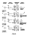
- FIGS. 2 a and 2 b show in tabular form the connections between a travel transmitter position, an actual value of a movement detection device, a position of an oscillation exciter and a resulting travel movement in the case of a ground-compaction device in accordance with the invention in different operational states;
- FIGS. 3 a to 3 e show a schematic plan view of oscillation exciter and propulsion combinations in the case of a ground-compaction device in accordance with the invention.
- FIGS. 4 a to 4 d show a schematic plan view of different embodiments of a ground-compaction system in accordance with the invention.
- the invention will be explained with reference to a remote-controllable vibration plate which is illustrated in FIG. 1 and is used as a ground-compaction device.
- the invention can also be applied to different ground-compaction devices, such as e.g. rollers or non-remote-controlled vibration plates.
- the vibration plate comprises a ground-contact plate 1 , on which there is mounted, as already explained above with reference to the prior art, a dual-shaft oscillation exciter 2 which serves as an oscillation excitation device and whose second shaft supports two unbalanced masses which can be adjusted in phase position independently of each other.
- the dual-shaft oscillation exciter 2 is driven in a known manner by a motor 3 .
- the oscillation excitation device i.e. the dual-shaft oscillation exciter 2 simultaneously serves as a drive and as a steering device, so that the propulsion required to generate the travel speed, the forwards and reverse movement and a turning moment about the vertical axis of the vibration plate is generated by means of the dual-shaft oscillation exciter 2 .
- the vibration plate is operator-actuated by means of radio, infrared or cable via a remote-control 4 which serves as a travel transmitter and comprises a so-called joystick 4 a .
- the operator carries a control box, on which is disposed the joystick 4 a , a type of control lever, which can be moved in the X- and Y-direction.
- a deflection of the joystick 4 a in the X-direction effects forwards travel of the vibration plate, whereas a deflection of the joystick 4 a in the positive or negative Y-direction effects a corresponding rotation of the vibration plate to the left or to the right.
- a control signal which is generated by the remote-control 4 is transmitted via antennas 5 to the vibration plate, where it is evaluated for the purpose of adjusting the travel speed, the direction of travel and, where appropriate, the steering.
- the steering action i.e. primarily the generation of a yawing moment about the vertical axis of the vibration plate, is likewise performed by the oscillation excitation device which is this case is also used as a steering device. Therefore, in the case of the vibration plate as shown in FIG. 1 , the oscillation excitation device forms the drive and the steering device at the same time.
- the functions can also be taken on by separately constructed and separately operable devices.
- a suitable movement detection device 6 can be yawing rate sensors for detecting the rotation about the vertical axis of the vibration plate, gyro compasses or optical fiber gyroscopes for detecting changes in direction in relation to an inertial system, earth's magnetic field sensors for determining the relative position of the vibration plate in the earth's magnetic field, GPS-receivers or acceleration sensors.
- yawing rate sensors for detecting the rotation about the vertical axis of the vibration plate
- gyro compasses or optical fiber gyroscopes for detecting changes in direction in relation to an inertial system
- earth's magnetic field sensors for determining the relative position of the vibration plate in the earth's magnetic field
- GPS-receivers or acceleration sensors In order to enhance the measuring precision, it is frequently expedient to combine several of these devices to form one movement detection device 6 . For example, it is also possible to utilise movement detection devices for navigation systems from the field of automotive and aircraft construction.
- a signal which is generated by the movement detection device 6 and corresponds to the actual value for the travel movement is fed to a travel control device 7 which is also influenced by the desired value signal from the remote-control 4 .
- the travel control device 7 forms a difference, corresponding to a control deviation, between the actual value and the desired value.
- the travel control device 7 actuates the oscillation exciter 2 , i.e. the drive and the steering device in such a manner as to minimize the control deviation.
- the vibration plate is held with a high level of precision on the course desired by the operator.
- the movement detection device 6 provides actual values with respect to a rotational rate of the vibration plate or with respect to the alignment thereof, it is also possible to compare these actual values with corresponding desired values. Therefore, it is possible to adjust the position of the vibration plate, for example, whilst at a standstill, i.e. strictly speaking there is no direction of travel and travel speed is zero.
- FIGS. 2 a and 2 b illustrate in tabular form examples of the interaction of the essential components of the vibration plates in conjunction with different operational states.
- the columns of the table compare the joystick position, i.e. the position of the joystick 4 a on the remote-control 4 , a yawing rate signal as a representation of an actual value provided by the movement detection device 6 , the position of the unbalanced masses in the oscillation exciter 2 and the resulting travel movement of the vibration plate.
- the oscillation exciter 2 corresponds to the dual-shaft oscillation exciter described above, in which two shafts can be rotated in opposite directions but in synchronism and support unbalanced masses in each case.
- the unbalanced mass is divided up into two axially disposed partial masses which, despite rotating together on the associated shaft, can be adjusted in their phase position with respect to each other, as is evident by a comparison between FIG. 2 a - 1 and FIG. 2 a - 2 .
- FIG. 2 a - 1 the unbalanced masses are synchronised in the oscillation excitation device in such a manner as to be able to achieve maximum propulsion and thus maximum forwards speed of the vibration plate.
- the resulting force vectors are thus forwardly inclined at an angle of about 45°.
- This unbalanced position is effected by means of the joystick 4 a which provides a maximum X-value (in this case: 100).
- the yawing rate signal remains at a constant value, e.g. at zero, since the vibration plate does not rotate about its vertical axis.
- the yawing rate signal is a voltage, the progression of which is illustrated over time.
- FIG. 2 a - 1 also illustrates the case of a disturbance, e.g. by reason of ground unevenness.
- the yawing rate signal falls away (broken line), because the vibration plate performs a slight rotation.
- An increasing deviation between the desired value, which is specified by the joystick position, and the actual value is identified immediately by the travel control device 7 and is corrected by influencing the unbalanced positions and thus the resulting force vectors with the aim of keeping the yawing rate signal at zero.
- the vibration device if a change in direction occurs, e.g. because the external disturbance is excessive, a rotational rate thus becomes effective over a specific period of time or exceeds a limit value, then with the application of a suitable control principle it is possible for the vibration device to be rotated back to its initial direction of travel by generating an oppositely directed yawing moment which is effective over a corresponding period of time.
- the travel control device 7 is to be designed expediently such that it not only prevents rotation of the vibration plate when rotation is not required, but also allows a rotation caused by disruptive external influences to be compensated for by means of a counter-rotation.
- FIG. 2 a - 2 illustrates a drive state, in which the vibration plate executes a turn at the front to the left-hand side.
- the unbalanced masses in the oscillation excitation device 2 accordingly generate two different resulting force vectors such that—as seen in the direction of travel—the force vector on the right-hand side still has a forwards component, whereas the force vector on the left-hand side is merely directed vertically, i.e. is used exclusively for ground-compaction purposes but not for forwards travel.
- the rotation of the vibration plate causes the yawing rate signal to increase and it then remains at a constant value if the rotation of the vibration plate is constant.
- the desired value for the yawing rate signal is then produced from the joystick position, so that the travel control device 7 is immediately able to control any possible deviations in the yawing rate signal by influencing the unbalanced position.
- FIG. 2 a - 3 illustrates the case of a rotation of the vibration plate in a standing position to the left.
- the unbalanced masses generate resulting forces which are directed against each other, in order to effect maximum rotation.
- the yawing rate signal is kept accordingly at a maximum value.
- FIG. 2 a - 4 illustrates the vibration plate vibrating in a standing position, in which the oscillation excitation device does not generate any propulsion but merely vertically directed oscillations. Since the vibration plate does not perform any rotation, the yawing rate signal is at zero.
- the unbalanced masses are moved to a position, in which resulting force vectors are generated with maximum propulsive effect in the reverse travel direction. Provided that the movement is not disrupted, the yawing rate signal remains at zero.
- the yawing rate signal then increases to a positive value which as an example is to be equated in this case with a rotation of the vibration plate to the left—in relation to forwards travel.
- the joystick 4 a outputs merely some predetermined values for the X- and Y-co-ordinates. Therefore, the signal values +100, 0, ⁇ 100 are sufficient for the X-co-ordinates which determine the forwards or reverse travel direction.
- the yawing rate signal is at 0 volts, if the vibration plate does not perform a rotation.
- the yawing rate signal lies in the range of a positive voltage, if the vibration plate performs a rotation to the left, whereas the signal value becomes negative in the event of a rotation to the right.
- these definitions only serve to illustrate the invention. In practice, it is also possible to achieve other values for the yawing rate signal. As set forth above, it is also possible, instead of determining the yawing rate signal, to determine a different signal or a combination of several signals as the actual value for the travel movement.
- a measurement of the advance speed is performed simultaneously e.g. by means of an additional sensor.
- the vibration plate is able to pass through specified radii of curvature, i.e. it simultaneously performs a rotation and a forwards movement and not only a specified rotation which in unfavourable conditions also lead to a standing rotation.
- FIGS. 3 a to e illustrate schematic plan views of ground-compaction devices in accordance with the invention comprising a different arrangement of several oscillation excitation devices.
- each of the ground-compaction devices which are illustrated in FIGS. 3 a to 3 e and are also explained using the example of vibration plates is not provided with only one oscillation excitation device but rather with several oscillation excitation devices 10 , 11 , 12 .
- FIG. 3 a schematically illustrates a vibration plate, in which two oscillation excitation devices 10 , 11 are disposed in parallel with each other on a common ground-contact plate 13 .
- the oscillation excitation device 10 , 11 is only illustrated in a schematic manner and consists in each case of two parallel shafts 14 , 15 which are rotatably coupled together in a positive-locking manner and rotate in opposite directions and which each support an unbalanced mass 16 and are disposed in such a manner as to be adjustable in their relative phase position with respect to each other.
- Axial division of one of the unbalanced masses 16 on the associated shaft is not required but is also fundamentally possible in the case of the vibration plates illustrated in FIGS. 3 a to 3 e.
- the oscillation excitation devices 10 , 11 are disposed in parallel with each other, so as to be effective in the same direction of propulsion. By adjusting different strength and differently directed resulting force vectors of the two oscillation excitation devices 10 , 11 , it is possible to generate a yawing moment about a vertical axis 17 thus making it possible to steer the vibration plate.
- FIGS. 3 b - 3 d illustrate variations of the vibration plate shown in FIG. 3 a which could not be used in practice without the inventive stabilisation of the direction of travel.
- three oscillation excitation devices 10 , 11 , 12 are disposed on the ground-contact plate 13 .
- the middle one of the three oscillation excitation devices (designated by the reference numeral 11 ) does not automatically have to contribute to the propulsion and thus to the generation of a travel movement of the vibration plate.
- the middle oscillation excitation device 11 is used exclusively for the generation of a vertically directed oscillation.
- the middle oscillation excitation device 11 can be constructed in a correspondingly convenient manner. For example, it is therefore not necessary for the direction of the resulting force vector, which is generated by said oscillation excitation device, to be adjustable.
- FIG. 3 c illustrates an arrangement, in which the oscillation excitation devices 10 , 11 are disposed rotated about 90° with respect to each other on the common ground-contact plate 13 .
- the forwards travel movement of the vibration plate is illustrated by an arrow which is directed to the left. It is thus sufficient for normal forwards operation that only the oscillation excitation device 10 generates a forwardly directed force vector.
- the oscillation generated by the oscillation excitation device 11 is vertically directed.
- the oscillation of the oscillation excitation device 11 can also be provided with a horizontal component, which effects a rotation of the vibration plate.
- FIG. 3 d illustrates two examples of the arrangement of three oscillation excitation devices 10 , 11 , 12 , wherein in each case the middle oscillation excitation device 11 is offset by 90° with respect to the other oscillation excitation devices 10 , 12 .
- FIG. 3 e shows a further embodiment of the invention, in which two oscillation excitation devices 10 , 11 are disposed one above the other.
- the exciter axes are perpendicular with respect to each other.
- the resulting force vector can be aligned in any manner about the vertical axis of the vibration plate extending in the middle.
- the resulting force vector acts in the centre of gravity of the vibration plate.
- the oscillation excitation devices 10 , 11 are attached jointly on one ground-contact plate 18 which comprises a substantially circular outline.
- This type of vibration plate can be moved in a problem-free manner in all directions, without it being necessary to take an otherwise typical main direction into account.
- the ground-compaction devices illustrated in FIGS. 3 a to 3 e have the advantage over hitherto known vibration plates that without the use of the inventive travel control facility, the arrangements of oscillation excitation devices shown here by way of example would comprise a high degree of instability in the direction of travel, which as a result would constitute a considerable burden on the operator during practical handling, even in the case of hand-held, i.e. non-remote-controlled ground-compaction devices.
- the inventive travel control device it is possible, even in the case of oscillation excitation device shafts which rotate at different frequencies, to control e.g. directional stability required by the operator as constantly as turning moments about the vertical axis generated by ground conditions are compensated.
- oscillation excitation devices can be mounted on the common ground-contact plate and can be actuated—at least partially—by the travel control device.
- FIGS. 4 a to 4 d show in schematic plan views ground-compaction systems in accordance with the invention which consist in each case of several vibration plates 21 , 22 , 23 and are connected together by means of a connection structure in a directionally stable manner, in such a way as to be height-adjustable relative to one another and, where appropriate, also in an elastic manner or movably with multiple degrees of freedom.
- FIG. 4 a illustrates a ground-compaction system in accordance with the invention having two vibration plates 21 , 22 which are connected together by means of connection elements 24 .
- Each of the vibration plates 21 , 22 supports an oscillation excitation device 25 , as already explained in conjunction with FIGS. 3 a to 3 e.
- connection structure connects the vibration plates 21 , 22 to the connection elements 24 in a suitable manner such that the vibration plates 21 , 22 are not able to rotate with respect to each other, but are kept in their respective direction.
- relative mobility is possible and expedient for the purpose of compensating for any ground unevenness and for the unnecessary synchronisation of the oscillation of the vibration plates.
- the oscillation excitation devices 25 on each of the vibration plates 21 , 22 serve at the same time as the drive for generating a propulsive movement. However, it is fundamentally possible to separate the function of the oscillation excitation device from the drive. As already described above, in the case of a known dual-shaft oscillation exciter it is possible to generate a considerable vertical oscillation, without effecting a propulsive movement, if the resulting force vectors are perpendicular (cf. e.g. FIG. 2 a - 4 ).
- FIG. 4 b shows three vibration plates 21 , 22 , 23 which are disposed in parallel with each other and which are likewise connected together in each case by means of the connection elements 24 and each support an oscillation excitation device 25 .
- FIG. 4 c shows two vibration plates 21 , 22 , on which is attached in each case an oscillation excitation device 25 , wherein the direction of propulsion of the two oscillation excitation devices 25 is, however, rotated about 90° with respect to each other.
- the oscillation exciter systems of the vibration plates can be operated without any synchronisation or in synchronism with each other.
- One of the vibration plates 21 serves to generate the propulsion of the entire ground-compaction system, whereas the second vibration plate 22 is used for directional control as well as ground-compaction purposes.
- the resulting force vector of the vibration plate 22 provided for directional control purposes is directed in a perpendicular manner with respect to the plane or is directed oscillating to the left and the right in a controlled manner, in order to introduce e.g. thrust stresses into the material to be compacted.
- FIG. 4 d shows arrangements of three vibration plates 21 , 22 , 23 which are coupled together, wherein in each case one oscillation excitation device 26 is disposed rotated about 90° with respect to the other oscillation excitation devices 25 .
- the respective oscillation excitation device comprises the already described two shafts 14 , 15 which can be rotated in opposite directions in a synchronised manner and each support an unbalanced mass, of which the phase position can be adjusted.
- the respective oscillation excitation device comprises the already described two shafts 14 , 15 which can be rotated in opposite directions in a synchronised manner and each support an unbalanced mass, of which the phase position can be adjusted.
- the oscillation excitation device of the middle vibration plate not even the phase position needs to be adjustable.
- the ground-compaction system is provided with a movement detection device as in the case of the ground-compaction device described with reference to FIG. 1 .
- the movement detection device e.g. a yawing rate sensor or a different device already described above, detects an actual value of the travel movement of the entire ground-compaction system.
- the actual value is compared with a desired value which is specified by the operator via the remote-control.
- the travel control device controls any control deviations by actuating the respective oscillation exciters in the vibration plates.
- the travel control device has algorithms stored in it which permit an unequivocal allocation of the steering functions.
- the travel control device only has to adjust a suitable oscillation exciter of the vibration plates for a short period, in order to instigate a corrective movement.
- the ground-compaction system has the advantage that the associated vibration plates can be constructed in a very convenient manner, since they do not require a dedicated steering device. It is only necessary to adjust the direction of the resulting force vector.
- several vibration plates can be combined to form one large unit having a corresponding level of working power.
Landscapes
- Engineering & Computer Science (AREA)
- Structural Engineering (AREA)
- Civil Engineering (AREA)
- Architecture (AREA)
- Life Sciences & Earth Sciences (AREA)
- Environmental & Geological Engineering (AREA)
- General Life Sciences & Earth Sciences (AREA)
- Mining & Mineral Resources (AREA)
- Paleontology (AREA)
- Soil Sciences (AREA)
- General Engineering & Computer Science (AREA)
- Agronomy & Crop Science (AREA)
- Road Paving Machines (AREA)
Applications Claiming Priority (3)
| Application Number | Priority Date | Filing Date | Title |
|---|---|---|---|
| DE10053446.5 | 2000-10-27 | ||
| DE10053446A DE10053446B4 (de) | 2000-10-27 | 2000-10-27 | Lenkbare Vibrationsplatte und fahrbares Vibrationsplattensystem |
| PCT/EP2001/011793 WO2002035005A1 (de) | 2000-10-27 | 2001-10-11 | Fahrbare bodenverdichtungsvorrichtung mit fahrtrichtungsstabilisierung |
Publications (2)
| Publication Number | Publication Date |
|---|---|
| US20040022582A1 US20040022582A1 (en) | 2004-02-05 |
| US6846128B2 true US6846128B2 (en) | 2005-01-25 |
Family
ID=7661359
Family Applications (1)
| Application Number | Title | Priority Date | Filing Date |
|---|---|---|---|
| US10/398,728 Expired - Fee Related US6846128B2 (en) | 2000-10-27 | 2001-10-11 | Mobile soil compacting device whose direction of travel is stabilized |
Country Status (5)
| Country | Link |
|---|---|
| US (1) | US6846128B2 (ja) |
| EP (1) | EP1328685B1 (ja) |
| JP (1) | JP3921446B2 (ja) |
| DE (2) | DE10053446B4 (ja) |
| WO (1) | WO2002035005A1 (ja) |
Cited By (48)
| Publication number | Priority date | Publication date | Assignee | Title |
|---|---|---|---|---|
| US20060193693A1 (en) * | 2005-02-28 | 2006-08-31 | Caterpillar Inc. | Self-propelled plate compactor having linear excitation |
| US20060263147A1 (en) * | 2005-05-20 | 2006-11-23 | Mccoskey William D | Asphalt compaction device |
| US20080298893A1 (en) * | 2005-12-07 | 2008-12-04 | Wacker Construction Equipment Ag | Vibration Plate with Stabilizing Device |
| US20080307748A1 (en) * | 2007-03-16 | 2008-12-18 | Marsh Roger F | Special equipment and improved methods to install a unitized post tension block system for masonry structures |
| US20090166050A1 (en) * | 2006-02-22 | 2009-07-02 | Wacker Construction Equipment Ag | Method and Device for Measuring Soil Parameters by Means of Compaction Machines |
| US20090306826A1 (en) * | 2005-07-01 | 2009-12-10 | Wacker Construction Equipment Ag | Vibrating Plate System |
| US20100166499A1 (en) * | 2005-06-24 | 2010-07-01 | Wacker Construction Equipment Ag | Vibrating Plate with Individually Adjustable Vibration Generators |
| US20100254769A1 (en) * | 2004-03-25 | 2010-10-07 | Wacker Construction Equipment Ag | Tamping Device |
| US20100303546A1 (en) * | 2005-06-24 | 2010-12-02 | Wacker Neuson Se | Soil Compacting Device with Automatic or Operator-Intuitive Adjustment of the Advance Vector |
| US9303368B2 (en) * | 2014-07-30 | 2016-04-05 | Shaker Ahmed REDA | Method for scanning and repairing road corrosion and apparatus therefor |
| US9347185B2 (en) * | 2014-07-30 | 2016-05-24 | Shaker Ahmed REDA | Method and apparatus for scanning and repairing road damage |
| US10047500B2 (en) | 2014-11-07 | 2018-08-14 | Wacker Neuson Production Americas Llc | Remote controlled compaction machine |
| US20190186083A1 (en) * | 2017-12-18 | 2019-06-20 | Somero Enterprises, Inc. | Screeding machine with column block control using gyro sensor |
| US20190234030A1 (en) * | 2016-04-06 | 2019-08-01 | Bomag Gmbh | Method for operating a ground milling machine, ground milling machine with a mobile component and mobile component for a ground milling machine |
| US10961669B2 (en) * | 2018-01-12 | 2021-03-30 | Terex Usa, Llc | System and method for changing a surface characteristic of a concrete bridge surface |
| US11079725B2 (en) | 2019-04-10 | 2021-08-03 | Deere & Company | Machine control using real-time model |
| US11178818B2 (en) | 2018-10-26 | 2021-11-23 | Deere & Company | Harvesting machine control system with fill level processing based on yield data |
| US11234366B2 (en) | 2019-04-10 | 2022-02-01 | Deere & Company | Image selection for machine control |
| US11240961B2 (en) | 2018-10-26 | 2022-02-08 | Deere & Company | Controlling a harvesting machine based on a geo-spatial representation indicating where the harvesting machine is likely to reach capacity |
| US20220110251A1 (en) | 2020-10-09 | 2022-04-14 | Deere & Company | Crop moisture map generation and control system |
| US11467605B2 (en) | 2019-04-10 | 2022-10-11 | Deere & Company | Zonal machine control |
| US11474523B2 (en) | 2020-10-09 | 2022-10-18 | Deere & Company | Machine control using a predictive speed map |
| US11477940B2 (en) | 2020-03-26 | 2022-10-25 | Deere & Company | Mobile work machine control based on zone parameter modification |
| US11592822B2 (en) | 2020-10-09 | 2023-02-28 | Deere & Company | Machine control using a predictive map |
| US11589509B2 (en) | 2018-10-26 | 2023-02-28 | Deere & Company | Predictive machine characteristic map generation and control system |
| US11635765B2 (en) | 2020-10-09 | 2023-04-25 | Deere & Company | Crop state map generation and control system |
| US11641800B2 (en) | 2020-02-06 | 2023-05-09 | Deere & Company | Agricultural harvesting machine with pre-emergence weed detection and mitigation system |
| US11650587B2 (en) | 2020-10-09 | 2023-05-16 | Deere & Company | Predictive power map generation and control system |
| US11653588B2 (en) | 2018-10-26 | 2023-05-23 | Deere & Company | Yield map generation and control system |
| US11672203B2 (en) | 2018-10-26 | 2023-06-13 | Deere & Company | Predictive map generation and control |
| US11675354B2 (en) | 2020-10-09 | 2023-06-13 | Deere & Company | Machine control using a predictive map |
| US11711995B2 (en) | 2020-10-09 | 2023-08-01 | Deere & Company | Machine control using a predictive map |
| US11727680B2 (en) | 2020-10-09 | 2023-08-15 | Deere & Company | Predictive map generation based on seeding characteristics and control |
| US11778945B2 (en) | 2019-04-10 | 2023-10-10 | Deere & Company | Machine control using real-time model |
| US11825768B2 (en) | 2020-10-09 | 2023-11-28 | Deere & Company | Machine control using a predictive map |
| US11844311B2 (en) | 2020-10-09 | 2023-12-19 | Deere & Company | Machine control using a predictive map |
| US11845449B2 (en) | 2020-10-09 | 2023-12-19 | Deere & Company | Map generation and control system |
| US11849671B2 (en) | 2020-10-09 | 2023-12-26 | Deere & Company | Crop state map generation and control system |
| US11849672B2 (en) | 2020-10-09 | 2023-12-26 | Deere & Company | Machine control using a predictive map |
| US11864483B2 (en) | 2020-10-09 | 2024-01-09 | Deere & Company | Predictive map generation and control system |
| US11874669B2 (en) | 2020-10-09 | 2024-01-16 | Deere & Company | Map generation and control system |
| US11889788B2 (en) | 2020-10-09 | 2024-02-06 | Deere & Company | Predictive biomass map generation and control |
| US11889787B2 (en) | 2020-10-09 | 2024-02-06 | Deere & Company | Predictive speed map generation and control system |
| US11895948B2 (en) | 2020-10-09 | 2024-02-13 | Deere & Company | Predictive map generation and control based on soil properties |
| US11927459B2 (en) | 2020-10-09 | 2024-03-12 | Deere & Company | Machine control using a predictive map |
| US11946747B2 (en) | 2020-10-09 | 2024-04-02 | Deere & Company | Crop constituent map generation and control system |
| US11957072B2 (en) | 2020-02-06 | 2024-04-16 | Deere & Company | Pre-emergence weed detection and mitigation system |
| US11983009B2 (en) | 2020-10-09 | 2024-05-14 | Deere & Company | Map generation and control system |
Families Citing this family (25)
| Publication number | Priority date | Publication date | Assignee | Title |
|---|---|---|---|---|
| US6673113B2 (en) * | 2001-10-18 | 2004-01-06 | Spinecore, Inc. | Intervertebral spacer device having arch shaped spring elements |
| DE10116526B4 (de) * | 2001-04-03 | 2004-04-01 | Wacker Construction Equipment Ag | Fernsteuerungseinrichtung für selbstfahrende Arbeitsgeräte |
| US20050143747A1 (en) * | 2001-07-16 | 2005-06-30 | Rafail Zubok | Parallel distractor and related methods for use in implanting an artificial intervertebral disc |
| US7713302B2 (en) * | 2001-10-01 | 2010-05-11 | Spinecore, Inc. | Intervertebral spacer device utilizing a spirally slotted belleville washer having radially spaced concentric grooves |
| US20080027548A9 (en) | 2002-04-12 | 2008-01-31 | Ferree Bret A | Spacerless artificial disc replacements |
| US8038713B2 (en) | 2002-04-23 | 2011-10-18 | Spinecore, Inc. | Two-component artificial disc replacements |
| DE10257892A1 (de) * | 2002-12-11 | 2004-06-24 | Bomag Gmbh | Vibrationsplatte |
| US6908484B2 (en) | 2003-03-06 | 2005-06-21 | Spinecore, Inc. | Cervical disc replacement |
| DE10317160A1 (de) * | 2003-04-14 | 2004-11-18 | Wacker Construction Equipment Ag | System und Verfahren zur automatisierten Bodenverdichtung |
| FR2867799B1 (fr) * | 2004-03-17 | 2007-11-02 | Jacques Robaey | Outil de pose de carrelages |
| DE102004014963B3 (de) * | 2004-03-26 | 2005-11-10 | Wacker Construction Equipment Ag | Flügelglätter mit Fahrtrichtungsstabilisierung |
| DE102004048459A1 (de) * | 2004-10-05 | 2006-04-13 | Wacker Construction Equipment Ag | Vibrationsplatte mit in Deichsel integrierbarer Fernsteuerung |
| DE102005029433A1 (de) * | 2005-06-24 | 2006-12-28 | Wacker Construction Equipment Ag | Vibrationsplatte mit winklig angeordneten Unwuchtwellen |
| DE202006020680U1 (de) | 2006-10-25 | 2009-09-03 | Wacker Neuson Se | Bodenverdichtungssystem mit positionsbezogener Dokumentation von Maschinen- und Verdichtungsdaten |
| DE202007019293U1 (de) | 2007-04-18 | 2011-11-22 | Wacker Neuson Produktion GmbH & Co. KG | Schwingungserreger für Bodenverdichtungsvorrichtungen |
| DE102007018353A1 (de) * | 2007-04-18 | 2008-10-30 | Wacker Construction Equipment Ag | Schwingungserreger für Bodenverdichtungsvorrichtungen |
| DE102007018743A1 (de) * | 2007-04-22 | 2008-10-23 | Bomag Gmbh | Verfahren und System zur Steuerung von Verdichtungsmaschinen |
| DE102011112316B4 (de) * | 2011-09-02 | 2020-06-10 | Bomag Gmbh | Schwingungserreger zur Erzeugung einer gerichteten Erregerschwingung |
| DE102011115008A1 (de) * | 2011-10-06 | 2013-04-11 | Wacker Neuson Produktion GmbH & Co. KG | Elektrowerkzeug mit Schutzhaube |
| US9677240B2 (en) * | 2012-09-05 | 2017-06-13 | M-B-W Inc. | Single direction vibratory plate |
| DE102014105023B4 (de) | 2013-04-10 | 2016-07-07 | Ammann Verdichtung Gmbh | Rüttelplatte und Verfahren zum Steuern einer Rüttelplatte |
| US20160340849A1 (en) * | 2015-05-18 | 2016-11-24 | M-B-W, Inc. | Vibration isolator for a pneumatic pole or backfill tamper |
| US9580879B1 (en) * | 2016-05-02 | 2017-02-28 | Jason A. Williams | Remotely-operable reciprocating compactor |
| DE102017109686B4 (de) * | 2017-05-05 | 2019-08-29 | Ammann Schweiz Ag | Bodenverdichtungsgerät |
| CN107142821A (zh) * | 2017-05-19 | 2017-09-08 | 台州瑞祥教育科技有限公司 | 一种地面建设用夯实机 |
Citations (14)
| Publication number | Priority date | Publication date | Assignee | Title |
|---|---|---|---|---|
| DE944922C (de) | 1953-12-15 | 1956-06-28 | Seitz Werke Gmbh | Maschine zum Fuellen und Verschliessen von Gefaessen |
| DE1213255B (de) | 1962-08-17 | 1966-03-24 | Electric Auto Lite Co | Landegestell fuer Hubschrauber, das wahlweise fuer amphibische Landevorgaenge eingerichtet werden kann |
| US3599543A (en) * | 1964-12-02 | 1971-08-17 | Stothert & Pitt Ltd | Vibratory machines |
| US4348901A (en) * | 1979-10-19 | 1982-09-14 | Koehring Gmbh-Bomag Division | Apparatus for monitoring the degree of compaction |
| US5164641A (en) * | 1990-05-28 | 1992-11-17 | Caterpillar Paving Products Inc. | Apparatus and method for controlling the frequency of vibration of a compacting machine |
| US5356238A (en) * | 1993-03-10 | 1994-10-18 | Cedarapids, Inc. | Paver with material supply and mat grade and slope quality control apparatus and method |
| US5695298A (en) * | 1993-03-08 | 1997-12-09 | Geodynamik H. Thurner Ab | Control of a compacting machine |
| US5727900A (en) * | 1993-10-14 | 1998-03-17 | Geodynamik H. Thurner Ab | Control of a compacting machine with a measurement of the characteristics of the ground material |
| US5942679A (en) * | 1993-04-29 | 1999-08-24 | Geodynamik Ht Aktiebolag | Compaction index |
| US6113309A (en) | 1996-08-20 | 2000-09-05 | Hollon; Edmund D. | Uniform compaction of asphalt concrete |
| WO2000056984A1 (de) | 1999-03-23 | 2000-09-28 | Wacker-Werke Gmbh & Co. Kg | Bodenverdichtungsvorrichtung mit servosteuerung |
| US6236923B1 (en) * | 1998-12-09 | 2001-05-22 | Caterpillar Inc. | Method and apparatus for controlling the inflation pressure of a pneumatic compactor |
| US20030047003A1 (en) * | 2001-09-05 | 2003-03-13 | Sakai Heavy Industries, Ltd. | Apparatus for managing degree of compaction in a vibratory compacting vehicle |
| US6558072B2 (en) * | 2001-05-15 | 2003-05-06 | Caterpillar Paving Products Inc. | Speed control system for a work machine |
Family Cites Families (6)
| Publication number | Priority date | Publication date | Assignee | Title |
|---|---|---|---|---|
| GB944922A (en) * | 1959-01-16 | 1963-12-18 | Losenhausenwerk Duesseldorfer | Road construction |
| DE1213355B (de) * | 1961-08-30 | 1966-03-24 | Losenhausenwerk | Bodenverdichter |
| DE7818542U1 (de) * | 1978-06-21 | 1982-10-14 | Wacker-Werke Gmbh & Co Kg, 8077 Reichertshofen | Schwingungserreger fuer plattenverdichter |
| DE3113693A1 (de) * | 1981-04-04 | 1982-10-21 | Weber Maschinentechnik Gmbh, 5928 Laasphe | Schwingungserreger fuer eine lenkbare ruettelplatte |
| US5149225A (en) * | 1991-03-13 | 1992-09-22 | M-B-W Inc. | Reversible drive for a vibratory compactor |
| DE4211284C1 (de) * | 1992-04-03 | 1993-09-30 | Delmag Maschinenfabrik | Rüttler |
-
2000
- 2000-10-27 DE DE10053446A patent/DE10053446B4/de not_active Expired - Fee Related
-
2001
- 2001-10-11 EP EP01988509A patent/EP1328685B1/de not_active Expired - Lifetime
- 2001-10-11 JP JP2002537967A patent/JP3921446B2/ja not_active Expired - Fee Related
- 2001-10-11 US US10/398,728 patent/US6846128B2/en not_active Expired - Fee Related
- 2001-10-11 WO PCT/EP2001/011793 patent/WO2002035005A1/de active IP Right Grant
- 2001-10-11 DE DE50108489T patent/DE50108489D1/de not_active Expired - Lifetime
Patent Citations (15)
| Publication number | Priority date | Publication date | Assignee | Title |
|---|---|---|---|---|
| DE944922C (de) | 1953-12-15 | 1956-06-28 | Seitz Werke Gmbh | Maschine zum Fuellen und Verschliessen von Gefaessen |
| DE1213255B (de) | 1962-08-17 | 1966-03-24 | Electric Auto Lite Co | Landegestell fuer Hubschrauber, das wahlweise fuer amphibische Landevorgaenge eingerichtet werden kann |
| US3599543A (en) * | 1964-12-02 | 1971-08-17 | Stothert & Pitt Ltd | Vibratory machines |
| US4348901A (en) * | 1979-10-19 | 1982-09-14 | Koehring Gmbh-Bomag Division | Apparatus for monitoring the degree of compaction |
| US5164641A (en) * | 1990-05-28 | 1992-11-17 | Caterpillar Paving Products Inc. | Apparatus and method for controlling the frequency of vibration of a compacting machine |
| US5695298A (en) * | 1993-03-08 | 1997-12-09 | Geodynamik H. Thurner Ab | Control of a compacting machine |
| US5401115A (en) * | 1993-03-10 | 1995-03-28 | Cedarapids, Inc. | Paver with material supply and mat grade and slope quality control apparatus and method |
| US5356238A (en) * | 1993-03-10 | 1994-10-18 | Cedarapids, Inc. | Paver with material supply and mat grade and slope quality control apparatus and method |
| US5942679A (en) * | 1993-04-29 | 1999-08-24 | Geodynamik Ht Aktiebolag | Compaction index |
| US5727900A (en) * | 1993-10-14 | 1998-03-17 | Geodynamik H. Thurner Ab | Control of a compacting machine with a measurement of the characteristics of the ground material |
| US6113309A (en) | 1996-08-20 | 2000-09-05 | Hollon; Edmund D. | Uniform compaction of asphalt concrete |
| US6236923B1 (en) * | 1998-12-09 | 2001-05-22 | Caterpillar Inc. | Method and apparatus for controlling the inflation pressure of a pneumatic compactor |
| WO2000056984A1 (de) | 1999-03-23 | 2000-09-28 | Wacker-Werke Gmbh & Co. Kg | Bodenverdichtungsvorrichtung mit servosteuerung |
| US6558072B2 (en) * | 2001-05-15 | 2003-05-06 | Caterpillar Paving Products Inc. | Speed control system for a work machine |
| US20030047003A1 (en) * | 2001-09-05 | 2003-03-13 | Sakai Heavy Industries, Ltd. | Apparatus for managing degree of compaction in a vibratory compacting vehicle |
Cited By (59)
| Publication number | Priority date | Publication date | Assignee | Title |
|---|---|---|---|---|
| US20100254769A1 (en) * | 2004-03-25 | 2010-10-07 | Wacker Construction Equipment Ag | Tamping Device |
| US8047742B2 (en) * | 2004-03-25 | 2011-11-01 | Wacker Neuson Produktion GmbH & Co. KG | Tamping device |
| US7354221B2 (en) * | 2005-02-28 | 2008-04-08 | Caterpillar Inc. | Self-propelled plate compactor having linear excitation |
| US20060193693A1 (en) * | 2005-02-28 | 2006-08-31 | Caterpillar Inc. | Self-propelled plate compactor having linear excitation |
| US20060263147A1 (en) * | 2005-05-20 | 2006-11-23 | Mccoskey William D | Asphalt compaction device |
| US7144195B1 (en) * | 2005-05-20 | 2006-12-05 | Mccoskey William D | Asphalt compaction device |
| US8602680B2 (en) * | 2005-06-24 | 2013-12-10 | Wacker Neuson Produktion GmbH & Co., KG | Soil compacting device with automatic or operator-intuitive adjustment of the advance vector |
| US20100303546A1 (en) * | 2005-06-24 | 2010-12-02 | Wacker Neuson Se | Soil Compacting Device with Automatic or Operator-Intuitive Adjustment of the Advance Vector |
| US20100166499A1 (en) * | 2005-06-24 | 2010-07-01 | Wacker Construction Equipment Ag | Vibrating Plate with Individually Adjustable Vibration Generators |
| US20090306826A1 (en) * | 2005-07-01 | 2009-12-10 | Wacker Construction Equipment Ag | Vibrating Plate System |
| US8046105B2 (en) * | 2005-07-01 | 2011-10-25 | Wacker Neuson Produktion GmbH & Co. KG | Vibrating plate system |
| US20080298893A1 (en) * | 2005-12-07 | 2008-12-04 | Wacker Construction Equipment Ag | Vibration Plate with Stabilizing Device |
| US20090166050A1 (en) * | 2006-02-22 | 2009-07-02 | Wacker Construction Equipment Ag | Method and Device for Measuring Soil Parameters by Means of Compaction Machines |
| US8057124B2 (en) * | 2006-02-22 | 2011-11-15 | Wacker Neuson Produktion GmbH & Co. KG | Method and device for measuring soil parameters by means of compaction machines |
| US20080307748A1 (en) * | 2007-03-16 | 2008-12-18 | Marsh Roger F | Special equipment and improved methods to install a unitized post tension block system for masonry structures |
| US9303368B2 (en) * | 2014-07-30 | 2016-04-05 | Shaker Ahmed REDA | Method for scanning and repairing road corrosion and apparatus therefor |
| US9347185B2 (en) * | 2014-07-30 | 2016-05-24 | Shaker Ahmed REDA | Method and apparatus for scanning and repairing road damage |
| US10047500B2 (en) | 2014-11-07 | 2018-08-14 | Wacker Neuson Production Americas Llc | Remote controlled compaction machine |
| US20190234030A1 (en) * | 2016-04-06 | 2019-08-01 | Bomag Gmbh | Method for operating a ground milling machine, ground milling machine with a mobile component and mobile component for a ground milling machine |
| US20190186083A1 (en) * | 2017-12-18 | 2019-06-20 | Somero Enterprises, Inc. | Screeding machine with column block control using gyro sensor |
| US10895045B2 (en) * | 2017-12-18 | 2021-01-19 | Somero Enterprises, Inc. | Concrete screeding machine with column block control using gyro sensor |
| US10961669B2 (en) * | 2018-01-12 | 2021-03-30 | Terex Usa, Llc | System and method for changing a surface characteristic of a concrete bridge surface |
| US11767647B2 (en) | 2018-01-12 | 2023-09-26 | Terex Usa, Llc | System and method for changing a surface characteristic of a concrete bridge surface |
| US11589509B2 (en) | 2018-10-26 | 2023-02-28 | Deere & Company | Predictive machine characteristic map generation and control system |
| US11178818B2 (en) | 2018-10-26 | 2021-11-23 | Deere & Company | Harvesting machine control system with fill level processing based on yield data |
| US11240961B2 (en) | 2018-10-26 | 2022-02-08 | Deere & Company | Controlling a harvesting machine based on a geo-spatial representation indicating where the harvesting machine is likely to reach capacity |
| US11672203B2 (en) | 2018-10-26 | 2023-06-13 | Deere & Company | Predictive map generation and control |
| US11653588B2 (en) | 2018-10-26 | 2023-05-23 | Deere & Company | Yield map generation and control system |
| US11778945B2 (en) | 2019-04-10 | 2023-10-10 | Deere & Company | Machine control using real-time model |
| US11234366B2 (en) | 2019-04-10 | 2022-02-01 | Deere & Company | Image selection for machine control |
| US11829112B2 (en) | 2019-04-10 | 2023-11-28 | Deere & Company | Machine control using real-time model |
| US11650553B2 (en) | 2019-04-10 | 2023-05-16 | Deere & Company | Machine control using real-time model |
| US11079725B2 (en) | 2019-04-10 | 2021-08-03 | Deere & Company | Machine control using real-time model |
| US11467605B2 (en) | 2019-04-10 | 2022-10-11 | Deere & Company | Zonal machine control |
| US11957072B2 (en) | 2020-02-06 | 2024-04-16 | Deere & Company | Pre-emergence weed detection and mitigation system |
| US11641800B2 (en) | 2020-02-06 | 2023-05-09 | Deere & Company | Agricultural harvesting machine with pre-emergence weed detection and mitigation system |
| US11477940B2 (en) | 2020-03-26 | 2022-10-25 | Deere & Company | Mobile work machine control based on zone parameter modification |
| US11825768B2 (en) | 2020-10-09 | 2023-11-28 | Deere & Company | Machine control using a predictive map |
| US11849672B2 (en) | 2020-10-09 | 2023-12-26 | Deere & Company | Machine control using a predictive map |
| US11711995B2 (en) | 2020-10-09 | 2023-08-01 | Deere & Company | Machine control using a predictive map |
| US11727680B2 (en) | 2020-10-09 | 2023-08-15 | Deere & Company | Predictive map generation based on seeding characteristics and control |
| US20220110251A1 (en) | 2020-10-09 | 2022-04-14 | Deere & Company | Crop moisture map generation and control system |
| US11650587B2 (en) | 2020-10-09 | 2023-05-16 | Deere & Company | Predictive power map generation and control system |
| US11635765B2 (en) | 2020-10-09 | 2023-04-25 | Deere & Company | Crop state map generation and control system |
| US11474523B2 (en) | 2020-10-09 | 2022-10-18 | Deere & Company | Machine control using a predictive speed map |
| US11844311B2 (en) | 2020-10-09 | 2023-12-19 | Deere & Company | Machine control using a predictive map |
| US11845449B2 (en) | 2020-10-09 | 2023-12-19 | Deere & Company | Map generation and control system |
| US11849671B2 (en) | 2020-10-09 | 2023-12-26 | Deere & Company | Crop state map generation and control system |
| US11675354B2 (en) | 2020-10-09 | 2023-06-13 | Deere & Company | Machine control using a predictive map |
| US11864483B2 (en) | 2020-10-09 | 2024-01-09 | Deere & Company | Predictive map generation and control system |
| US11871697B2 (en) | 2020-10-09 | 2024-01-16 | Deere & Company | Crop moisture map generation and control system |
| US11874669B2 (en) | 2020-10-09 | 2024-01-16 | Deere & Company | Map generation and control system |
| US11889788B2 (en) | 2020-10-09 | 2024-02-06 | Deere & Company | Predictive biomass map generation and control |
| US11889787B2 (en) | 2020-10-09 | 2024-02-06 | Deere & Company | Predictive speed map generation and control system |
| US11895948B2 (en) | 2020-10-09 | 2024-02-13 | Deere & Company | Predictive map generation and control based on soil properties |
| US11927459B2 (en) | 2020-10-09 | 2024-03-12 | Deere & Company | Machine control using a predictive map |
| US11946747B2 (en) | 2020-10-09 | 2024-04-02 | Deere & Company | Crop constituent map generation and control system |
| US11592822B2 (en) | 2020-10-09 | 2023-02-28 | Deere & Company | Machine control using a predictive map |
| US11983009B2 (en) | 2020-10-09 | 2024-05-14 | Deere & Company | Map generation and control system |
Also Published As
| Publication number | Publication date |
|---|---|
| DE10053446A1 (de) | 2002-06-06 |
| EP1328685B1 (de) | 2005-12-21 |
| WO2002035005A1 (de) | 2002-05-02 |
| DE10053446B4 (de) | 2006-03-02 |
| JP2004518041A (ja) | 2004-06-17 |
| DE50108489D1 (de) | 2006-01-26 |
| US20040022582A1 (en) | 2004-02-05 |
| JP3921446B2 (ja) | 2007-05-30 |
| EP1328685A1 (de) | 2003-07-23 |
Similar Documents
| Publication | Publication Date | Title |
|---|---|---|
| US6846128B2 (en) | Mobile soil compacting device whose direction of travel is stabilized | |
| US8047742B2 (en) | Tamping device | |
| JP7129873B2 (ja) | 自動均し作業ロボット | |
| JP6552420B2 (ja) | 作業車 | |
| EP2944727B1 (en) | Automatic control of a joystick for dozer blade control | |
| US11375706B2 (en) | Regulating and/or control system, agricultural machine comprising such a system, and method for operating an agricultural machine | |
| US5924512A (en) | Omnidirectional vehicle and method of controlling the same | |
| US7661627B2 (en) | Method of controlling the attitude of satellites, particularly agile satellites with a reduced number of gyrodynes | |
| CN105531182A (zh) | 两轮陀螺稳定车辆及用于控制这样的车辆的方法 | |
| JP2021104034A (ja) | 作業車 | |
| KR100351377B1 (ko) | 원격제어 헬리콥터용 자이로 장치 | |
| US20220136184A1 (en) | Method for compacting asphalt material | |
| US20200180168A1 (en) | Working robot | |
| JP6811655B2 (ja) | 作業車 | |
| JP2003521424A (ja) | 宇宙船の姿勢を制御するシステムおよび方法 | |
| JP6850759B2 (ja) | 自律操舵装置 | |
| US6789437B2 (en) | Apparatus for precision slewing of flatform-mounted devices | |
| US6354163B1 (en) | Mitigating gimbal induced disturbances in CMG arrays | |
| US20040103730A1 (en) | Vibration generator for a soil compacting device | |
| EP0834761B1 (en) | Image stabilizing apparatus | |
| US20220341103A1 (en) | Compacting roller with an electronic balancing system for maintaining the roller in an upright position | |
| US6655871B1 (en) | Vibration exciter for ground compacting devices | |
| RU2497728C2 (ru) | Способ ориентации космического аппарата в путевой системе координат с приводом поворота аппаратуры наблюдения наземных объектов и устройство для его осуществления | |
| JPH07300096A (ja) | 無人ヘリコプタの姿勢制御装置 | |
| JPH0370700A (ja) | 垂直離着飛行体の飛行制御方法 |
Legal Events
| Date | Code | Title | Description |
|---|---|---|---|
| AS | Assignment |
Owner name: WACKER CONSTUCTION EQUIPMENT AG, GERMANY Free format text: ASSIGNMENT OF ASSIGNORS INTEREST;ASSIGNOR:SICK, GEORG;REEL/FRAME:014233/0133 Effective date: 20030331 |
|
| FPAY | Fee payment |
Year of fee payment: 4 |
|
| AS | Assignment |
Owner name: WACKER NEUSON SE,GERMANY Free format text: CHANGE OF NAME;ASSIGNOR:WACKER CONSTRUCTION EQUIPMENT AG;REEL/FRAME:024515/0259 Effective date: 20091002 Owner name: WACKER NEUSON SE, GERMANY Free format text: CHANGE OF NAME;ASSIGNOR:WACKER CONSTRUCTION EQUIPMENT AG;REEL/FRAME:024515/0259 Effective date: 20091002 |
|
| AS | Assignment |
Owner name: WACKER NEUSON PRODUKTION GMBH & CO. KG, GERMANY Free format text: NUNC PRO TUNC ASSIGNMENT;ASSIGNOR:WACKER NEUSON SE;REEL/FRAME:026955/0859 Effective date: 20110829 |
|
| FPAY | Fee payment |
Year of fee payment: 8 |
|
| REMI | Maintenance fee reminder mailed | ||
| LAPS | Lapse for failure to pay maintenance fees | ||
| STCH | Information on status: patent discontinuation |
Free format text: PATENT EXPIRED DUE TO NONPAYMENT OF MAINTENANCE FEES UNDER 37 CFR 1.362 |
|
| FP | Expired due to failure to pay maintenance fee |
Effective date: 20170125 |