US6826930B2 - Method and apparatus for moving the stitches of a knitted tubular article to an operating station - Google Patents
Method and apparatus for moving the stitches of a knitted tubular article to an operating station Download PDFInfo
- Publication number
- US6826930B2 US6826930B2 US10/484,853 US48485304A US6826930B2 US 6826930 B2 US6826930 B2 US 6826930B2 US 48485304 A US48485304 A US 48485304A US 6826930 B2 US6826930 B2 US 6826930B2
- Authority
- US
- United States
- Prior art keywords
- stitches
- members
- carrier
- article
- station
- Prior art date
- Legal status (The legal status is an assumption and is not a legal conclusion. Google has not performed a legal analysis and makes no representation as to the accuracy of the status listed.)
- Expired - Fee Related
Links
Images


Classifications
-
- D—TEXTILES; PAPER
- D04—BRAIDING; LACE-MAKING; KNITTING; TRIMMINGS; NON-WOVEN FABRICS
- D04B—KNITTING
- D04B15/00—Details of, or auxiliary devices incorporated in, weft knitting machines, restricted to machines of this kind
- D04B15/18—Dials
-
- D—TEXTILES; PAPER
- D04—BRAIDING; LACE-MAKING; KNITTING; TRIMMINGS; NON-WOVEN FABRICS
- D04B—KNITTING
- D04B9/00—Circular knitting machines with independently-movable needles
- D04B9/42—Circular knitting machines with independently-movable needles specially adapted for producing goods of particular configuration
- D04B9/46—Circular knitting machines with independently-movable needles specially adapted for producing goods of particular configuration stockings, or portions thereof
- D04B9/56—Circular knitting machines with independently-movable needles specially adapted for producing goods of particular configuration stockings, or portions thereof heel or toe portions
-
- D—TEXTILES; PAPER
- D04—BRAIDING; LACE-MAKING; KNITTING; TRIMMINGS; NON-WOVEN FABRICS
- D04B—KNITTING
- D04B15/00—Details of, or auxiliary devices incorporated in, weft knitting machines, restricted to machines of this kind
- D04B15/02—Loop-transfer points
-
- D—TEXTILES; PAPER
- D04—BRAIDING; LACE-MAKING; KNITTING; TRIMMINGS; NON-WOVEN FABRICS
- D04B—KNITTING
- D04B9/00—Circular knitting machines with independently-movable needles
- D04B9/40—Circular knitting machines with independently-movable needles with provision for transfer of knitted goods from one machine to another
Definitions
- the present invention refers to a method and apparatus for handling or moving the stitches of a knitted article.
- U.S. Pat. Nos. 5,570,591 and 5,487,281 deal with the joining of two end edges of a tubular knitted article through a hook-up operation performed onto the right-side out article in correspondence of the machine which knits the article and, respectively, in correspondence of a station for a hook-up operation distinct from the knitting operation.
- U.S. Pat. No. 6,164,091 discloses a method of joining two terminal edges of tubular knitted article, which method makes it possible to carry out said junction by a hook-up operation involving either the right-side out or the inside-out part of the article.
- this known operating technique brings about some drawbacks deriving from the fact that provision is made for repeatedly transferring the stitches of the linked edges between a plurality of members for the removal and, more generally, the handling of same stitches.
- this technique implies that the said stitched are more likely to be missed or damaged and, in any case, of being subjected to mechanical stress which, especially when using yarns of lower quality, may be cause for unsuccessful operations.
- the means used result somewhat complex and, accordingly, considered too expensive in relation to the outcome. The above holds true also in case the knitting is performed by either a one-cylinder or two-cylinder machine.
- the main object of the present invention is to overcome the above drawbacks by ensuring in any case the possibility of joining two terminal edges of a tubular knitted machine through a hook-up operation which can be performed also on the inner or inside-out part of the article.
- the advantages of the present invention lies essentially in that the stitches to be handled or moved result subjected to minor stresses, which allows using, where deeming it suitable or necessary for economy, yarns of lower quality.
- the risk of damaging the stitches, as well as of hold-failure or disengagement of them from the handling members handling in the course of treatment is reduced.
- the relative constructional simplicity of the present apparatus which allows reducing the manufacturing and operating costs thereof.
- the invention makes it possible to perform a final hook-up operation both of the right-side out and inside-out part of the article, in correspondence of the two edges thereof to be united by a hook-up operation, such as in the case of stockings manufacturing, and this by knitting the stockings with machines of one-cylinder as well as two-cylinder type.
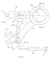
- FIG. 1 is a schematic view in diametral section of one-cylinder circular machine in a condition of end-of-knitting of a stocking, with the plate being still down;
- FIG. 2A shows the machine of FIG. 1 with the plate and the knitting needles being lifted, the stitches of the last knitted rank resulting in the so-called “unloaded” position;
- FIGS. 2B and 2C show, in different scales, enlarged details of the drawing in FIG. 2A;
- FIG. 3A shows a first movable carrier with the stitch-removing members disposed onto the needles of the machine of FIG. 2;
- FIG. 4A shows the said first movable carrier as it comes down together with the knitting needles to allow the transfer of the stitches of the last knitted rank from the removal members supported by the movable carrier;
- FIGS. 3B and 4B show, respectively, enlarged details of FIGS. 3A and 4A relating to the procedure for closing the latch of one needle where the stitch surface of the sinkers is used as a cast-off plane;
- FIGS. 3C and 4C show, respectively, enlarged details of FIGS. 3A and 4A relating to the procedure for closing the latch of one needle where the upper or “beak” surface of the sinkers is used as a cast-off plane;
- FIG. 5 shows the step of lifting the first movable carrier with the article being disengaged from the knitting needles and engaged with the said removal members
- FIG. 6 shows the step of moving a safety device close to the first movable carrier being lifted up
- FIG. 7 shows the first movable carrier and the safety device in the hook-up station, with a an eversion tube being inserted into the article, and a second movable carrier being disposed coaxial with the first movable carrier;
- FIG. 8 shows the step of lifting said eversion tube and of moving the two movable carrier close to each other
- FIG. 9 shows the final step of transferring the stitch-removing members from the first movable carrier to the second one
- FIG. 10 shows the step of moving a third to the second movable carrier, with the approach of the means supported by the third movable carrier to the stitch-removing members supported by the second movable carrier, and the transfer of stitches from the members of the second carrier to the third one;
- FIG. 11 shows the moving of the second movable carrier away from the third one
- FIG. 12 shows the step of positioning the stitches of a semirank in correspondence of those of the other semirank, the stitches involved in this step being those fitted beforehand onto said removal members;
- FIG. 13 shows the step of drawing and juxtaposing the stitches of the first semirank near the corresponding stitches of the second semirank
- FIG. 14 shows the restoration of the initial configuration of the third movable carrier
- FIG. 15 shows the step of hooking-up pairs of thus formed stitches
- FIG. 16 shows the step of releasing the article after the hooking-up of the edges corresponding to said semiranks
- FIG. 17 shows the transfer of said members for the removal of stitches of last-knitted rank from the second to the first movable carrier subsequently to the moving away of third carrier;
- FIG. 18 shows the step of moving the second movable carrier away from the first one, that is, the restoration of the initial conditions
- FIG. 19 shows, reference being made to a further exemplary embodiment of the invention, a first movable carrier having members associated therewith for the removal of stitches of the last-knitted rank, the said first movable carrier being disposed so that the said removal members will result upon the needles of the knitting machine, the said needles being lifted up as shown in FIG. 3A;
- FIG. 20 shows the step of lowering the movable carrier of FIG. 19 along with the knitting needles
- FIG. 21 shows the lifting of the movable carrier of FIG. 19 with the article being disengaged from the knitting needles and engaged with the removal members associated with same carrier;
- FIG. 22 shows the positioning of a safety device
- FIG. 23 shows the introduction of an eversion tube inside the article at a hook-up station separated from the knitting station
- FIG. 24 shows the lifting of the eversion tube of FIG. 23, subsequently to the moving away of the safety device, and the drawing of a second movable carrier near the first one to allow the transfer of the stitch-removing members from the first movable carrier to the second one;
- FIG. 25 shows the moving of the first movable carrier away from the second one
- FIG. 26 shows the step of drawing a third movable carrier near a portion of the second movable carrier, the said third carrier exhibiting a plurality of hook-up spines;
- FIG. 27 shows the step of transferring the stitches of a semirank from the respective removal members, associated with the second movable carrier, to the spines of the third carrier;
- FIG. 28 shows the moving of the second movable carrier away from the third carrier
- FIG. 29 shows the positioning of the stitches associated with said spines in correspondence of the stitches of the other semirank
- FIG. 30 shows the subsequent step of juxtaposing the stitches of said other semirank Over those fitted on said spines
- FIG. 31 shows the repositioning of the spines in the condition of FIG. 28;
- FIG. 32 shows the moving away of the first movable carrier being partially rearranged
- FIG. 33 shows the step of hooking-up the edges corresponding to the thus disposed semiranks of stitches
- FIG. 34 shows the step of releasing the article from the hold of the spines
- FIG. 35 shows the transfer of said stitch-removing members from the second movable carrier to the first carrier for the full rearrangement of the latter
- FIG. 36 shows the moving away of the second movable carrier with restoration of the initial conditions
- FIG. 37 shows a plan view of the first movable carrier illustrated in FIGS. 3A-18;
- FIG. 38 shows an enlarged detail in longitudinal section of the carrier of FIG. 37 in a condition of non retention of the stitch-removing members
- FIG. 39 shows the detail of FIG. 38 in a condition of retention of the stitch-removing members
- FIGS. 40 and 41 show an enlarged detail in longitudinal section of the carrier of FIG. 37, according to a further embodiment, in a condition of non-retention (FIG. 41) of the stitch-removing members;
- FIG. 42 is a plan view of the third movable carrier of FIGS. 3A-18;
- FIG. 43 shows the carrier of FIG. 42 in closed or operating condition
- FIG. 44 is a section view taken on line A—A in FIG. 43;
- FIG. 45 shows the carrier of FIG. 43 after the rotation of a semicrown
- FIG. 46 is a view in section view taken on line B—B in FIG. 45;
- FIG. 47 is a plan view of said three movable carriers in coaxial condition at the hook-up station
- FIG. 48 is a section view taken on line C—C in FIG. 47 showing also the second movable carrier and other parts in section other than those taken on line C—C;
- FIG. 49 is a side view partially in section of the third movable carrier shown in FIGS. 26-34;
- FIG. 50 is a plan view of the carrier of FIG. 49;
- FIG. 51 is a section view taken on line D—D in FIG. 50;
- FIG. 52 is a plan view of the carrier of FIG. 49 after a rotation through 180°;
- FIG. 53 is a section view taken on line E—E in FIG. 52;
- FIG. 54 is a diametral section view of the apparatus with the three movable carriers shown in FIGS. 19-36 in coaxial condition;
- FIG. 55 is a side view of a stitch-removing member
- FIG. 56 is a view in longitudinal section of the member of FIG. 55;
- FIG. 57 is an axonometric view of the member shown in FIG. 55;
- FIG. 58 is a side view of a stitch-removing member according to a further embodiment
- FIG. 59 is a view in longitudinal section of the member of FIG. 58;
- FIG. 60 is an axonometric view of the member shown in FIG. 58;
- FIG. 61 is a side view of a stitch-removing member according to a further embodiment
- FIG. 62 is a view in longitudinal section of the member of FIG. 61;
- FIG. 63 is an axonometric view of the member shown in FIG. 61;
- FIG. 64 is a schematic view in diametral section of two-cylinder circular machine in a condition of end-of-knitting of a stocking, with the upper cylinder being still down;
- FIG. 65 shows the machine of FIG. 64 with the upper cylinder being lifted up, the stitches of the last knitted rank resulting in the so-called “unloaded” position;
- FIG. 66 shows a first movable carrier with stitch-removing members disposed above the needles of the lower cylinder of the machine of FIG. 64;
- FIGS. 67 and 68 show the said first movable carrier as it goes down towards the lower cylinder to allow the transfer of the stitches of the last knitted rank from the needles to the removal members supported by the movable carrier;
- FIG. 69 shows the lifting of the movable carrier with the article being disengaged from the knitting needles of the lower cylinder and engaged with said removal members
- FIG. 70 shows the drawing of a safety device near the first movable carrier being lifted up
- FIG. 71 is a schematic view in diametral section of one-cylinder circular machine with the plate and knitting needles being lifted up, the stitches of the last knitted rank resulting in the so-called “unloaded” position;
- FIG. 72 shows a first movable carrier with the stitch-removing members being disposed onto the needles of the machine of FIG. 71 and with external means able to define a cast-off plane for the removal of the stitches;
- FIG. 73 shows the said first movable carrier in a step of transferring the last knitted rank from the needles of the machine of FIG. 71 to the removal members supported by the same movable carrier;
- FIG. 74 shows the step of lifting the first movable carrier with the article being disengaged from the knitting needles and engaged with the said removal members, this step being the one in which the said means defining the cast-off plane act as a safety device to prevent the spontaneous release or hold-failure of the stitches;
- FIG. 75 shows the first movable carrier and the said means acting as a safety device in the hook-up station, with an eversion tube being introduced into the article and with a second movable carrier disposed coaxial with the first movable carrier;
- FIG. 76 shows a step which precedes the approach of the two movable carriers, this step being the one in which the said means acting as a safety device are deactivated;
- FIG. 77 is a side partial side view with parts in section of a first movable carrier with the stitch-removing members being moved close to the needles and with the means apt to define a cast-off plane being off;
- FIG. 78 shows the example of FIG. 77, with the said means apt to define a cast-off plane being activated likewise illustrated in FIG. 72;
- FIG. 79 shows the example of FIG. 77, with the said means apt to define a cast-off plane being activated after the removal similarly to what is illustrated in FIG. 74;
- FIG. 80 shows the example of FIG. 79, with the said means apt to define a cast-off plane being activated after a removal like that illustrated in FIG. 76;
- FIG. 81 is a partial side view with parts in section of a first movable carrier, with the stitch-removing members being moved close to the needles, and where a further exemplary embodiment is shown of the means able to define a cast-off plane, said means being deactivated;
- FIG. 82 refers to the example of FIG. 81 and shows a step in which the said means apt to define a cast-off plane are activated;
- FIG. 83 shows an enlarged detail, in longitudinal section, of the second carrier (SE) in a condition of non-retention of the stitch-removing members;
- FIG. 84 shows the detail of FIG. 83 in a condition of non-retention of the stitch-removing members
- FIGS. 85 and 86 show an enlarged detail, in longitudinal section, of the second carrier (SE) according to a further embodiment, in a condition of non-retention (FIG. 85) of the stitch-removing members;
- FIG. 87 shows a plan view relative to a possible embodiment of the transfer rod ( 12 );
- FIG. 88 is a schematic rear view of the transfer rod of FIG. 87;
- FIGS. 89 and 90 are two views in diametral section of an exemplary embodiment relating to a possible way of using the transfer rod illustrated in FIGS. 87 and 88, said rod being in stand-by (FIG. 89) and respectively work (FIG. 90) position;
- FIG. 91 shows the step of ending the knitting of a stocking by a two-cylinder circular machine, with the stocking being in the upper cylinder;
- FIG. 92 shows a subsequent step in which the knitting needles are transferred from the lower to the upper cylinder
- FIG. 93 shows the lifting of the upper cylinder
- FIG. 94 shows the step of moving the first movable carrier between the lower and the upper cylinder, the latter being lifted up;
- FIG. 95 shows the drawing of the first movable carrier near the needles associated with the upper cylinder
- FIG. 96 shows the step of removing the stitches of the last knitted rank of the stocking of FIG. 91;
- FIG. 97 shows the lowering of the first movable carrier with the stitches of the last knitted rank being now engaged with the removal members mounted on said carrier;
- FIG. 98 shows the drawing up of a possible safety device
- FIG. 99 shows the introduction of an eversion tube into the article being transferred to a station other than that for knitting
- FIG. 100 shows the moving of the second movable carrier close to the first one and the turning right-side out of the stocking with a upwards movement of said everter tube;
- FIG. 101 shows the transfer of said stitch-removing members from the first movable carrier to the first one
- FIG. 102 shows the moving of the third movable carrier close to the second
- FIG. 103 shows the moving of the second movable carrier away from the third
- FIG. 104 shows an overturning through 180° of a semirank of stitches
- FIG. 105 shows a transfer of the overturned stitches onto the spines which support the stitches of the other semirank
- FIG. 106 shows the repositioning of the third movable carrier into its initial configuration
- FIG. 107 shows the step of hooking-up the article
- FIG. 108 the release of the stitches already retained by the said spines
- FIG. 109 shows a possible step of everting the stocking being released
- FIG. 110 shows the transfer of the stitch-removing members from the second movable carrier to the first one
- FIG. 111 shows the moving of the second movable carrier away from the first one
- FIGS. 112, 113 and 114 show a side view, a front view and respectively a plan view of the stitch-removing member according to a further embodiment
- FIG. 115 shows, in perspective view, a modified embodiment of the member shown in FIGS. 112-114;
- FIGS. 116-127 correspond to FIGS. 7-18 but refer to a modified embodiment of the process according to the invention.
- FIG. 128 shows a detail of the apparatus that can be used to implement the method of FIGS. 116 - 127 ;ù
- FIG. 129 is a view in diametral section of the apparatus of FIG. 128;
- FIG. 130 shows an enlarged detail of the drawing in FIG. 128
- FIGS. 131 and 132 show a detail of the apparatus that can be used to implement the method of FIGS. 116-127 in a non-retention and respectively retention or locking configuration of the rods ( 9 );
- FIGS. 133 and 134 show a variation of the apparatus illustrated in FIGS. 131 and 132;
- FIGS. 135-137 show three views of a spine associable with the apparatus of FIG. 128;
- FIG. 138 is a view in section on line U—U in FIG. 135;
- FIGS. 139-147 show diagrammatically a case of handling the stitches of a straight, instead of a tubular fabric.
- an operative method according to the invention related to the manufacturing of a stocking by means of a one-cylinder circular machine (M) provided with plate, includes the following steps:
- the plate group comprises the very plate ( 5 ) of circular configuration, movable from and to the machine (M) and supporting a plurality of radial crooks ( 6 ).
- the plate group ( 2 ) is drawn near the machine (M) as illustrated in FIG. 1 .
- such group is moved away from the machine (M) as illustrated in FIG. 2 A.
- the very knitting is carried out by forming a tubular assembly of linked loops or stitches by using one or more threads (not shown in the drawing) worked by the needles ( 2 ) in cooperation with the sinkers ( 4 ).
- the crooks ( 6 ) of the plate ( 5 ) can be used to make special parts of the article ( 1 ) such as a double edge of the hem.
- the crooks ( 6 ) and the needles ( 2 ) are suitable driven in phase between them and with the sinkers ( 4 ) by a system of cams acting on corresponding operating heels ( 20 , 40 , 60 ).
- FIG. 2A shows only the cams ( 400 ) with sinkers ( 4 ).
- a machine of this type is well known and available on the market. For example, use can be made of a machine model “Star” or “4100”, or “Fantasia”, or also “Tornado”, all made in Italy by the company Sangiacomo S.p.A., or of any other equivalent machine;
- the members ( 7 ) for removing the stitches from needles ( 2 ) may be mounted in a stable but removable manner, as best described later on, onto a first movable carrier (PE).
- each removal member ( 7 ) after lifting the plate (P), is disposed in axial alignment with the needles cylinder, so that the free end of each removal member ( 7 ) will result in contact with the crook ( 22 ) of a corresponding needle ( 2 ), as illustrated in FIGS. 3A and 3B, thereby determining a so-called “covering” condition allowing each stitch to be transferred from the respective needle ( 2 ) to the respective removal member ( 7 ) with no obstacle, that is, without being intercepted by the needle's crook. Under this condition, the crook is actually overlapped by the free end of member ( 7 ) which forms a cap onto the crook. Thereafter, the said carrier (PE) is lowered, as shown in FIGS.
- each stitch will result fitted onto a corresponding removal member ( 7 ) also because of the automatic closing of latches ( 21 ) which result positioned as shown in FIG. 4 B.
- the members ( 7 ) take up the place of the latter by enetering the stitches of the last rank.
- the plane used as a cast-off surface is the one in which the stitches are formed, that is, the so-called stitch plane (PM) of the sinkers.
- PM stitch plane
- the cast-off plane used is the upper surface (PS) of the sinkers (also called beak).
- PS the upper surface
- the “cast-off plane” is a surface for temporarily supporting or retaining the stitches (MA), and beyond which the stitches (MA) cannot be pushed. Accordingly, when the stitches (MA) lie in such a plane, the lowering of the needles ( 2 ) and the concurrent lowering of members ( 7 ) cause the passage or transfer of the stitches (MA) from the needles ( 2 ) to the members ( 7 );
- This step can be carried out by lifting the movable carrier (PE) and tube (T) at the same time, so that the mouth of the latter will result at a height greater than that of the free ends of the removal members ( 7 ), as illustrated in FIG. 5 .
- the lifting of tube (T) is not strictly necessary to carry out this step but it may serve to assist the lifting of article ( 1 ) simultaneously to the carrier (PE), and to prevent the disengagement of one or more stitches from the respective removal members ( 7 ).
- a safety device ( 8 ) made up, for example, of a portion of a circular crown borne at the end of a support arm ( 800 ) being movable from and to the carrier (PE) to accompany the article to the subsequent station (where it will be then moved away therefrom to allow the insertion of a second movable carrier (SE) (FIG. 6 );
- the eversion tube (TR) may be a tube with vertical axis (v-v) connected to a suction pump of a type commonly used in hosiery machines;
- this step can be performed by lifting the tube (TR), as illustrated in FIG. 8, after having moved away the device ( 8 ) if used.
- the article will result oriented in a manner opposite to the initial one, that is, with the part comprising the last rank of stitches turned upwards, so that the stitches of the latter rank will result below all the other stitches of the article;
- this step can be carried out by moving the second movable carrier (SE) close to the first (PE), as illustrated in FIG. 8 and, upon completion of transfer, by moving the first movable carrier (PE) away from the second (SE), as illustrated in FIG. 9 .
- the free ends of the members ( 7 ) will result those previously engaged with the first carrier (PE) and, vice versa, those previously free will result engaged with the second movable carrier (SE). Described later on are possible ways of making the carriers (PE) and (SE).
- the said stitch-retaining members for the hook-up ( 9 , 10 ) may consist, as best described later on, of a plurality of rods ( 9 ) of a shape similar to that of members ( 7 ), and of a plurality of hook-up spines as well mounted on two relevant supporting semicrowns.
- the transfer of the stitches from the members ( 7 ) to the rods ( 9 ) and to the spines ( 10 ) may be made by using a collar flange ( 11 ) coaxial to the second carrier (SE) and movable vertically from and to the third carrier (TE).
- a collar flange ( 11 ) coaxial to the second carrier (SE) and movable vertically from and to the third carrier (TE).
- the article Upon completion of this step, the article will no longer be engaged with the members ( 7 ) transferred onto the second carrier (SE), but will result engaged wiht the members ( 9 , 10 ) of the third movable carrier (TE), with the stitches of a semirank fitted on the rods ( 9 ) and with the stitches of the other semirank fitted on the spines ( 10 );
- this step can be carried out by moving the second movable carrier (SE) away from the third (FIG. 11 ), by rotating the semicrown of the rods ( 9 ) through 180° (for example downwards, as illustrated in FIG. 12 ), then by transferring onto the spines ( 10 ) the stitched fitted on rods ( 9 ) and finally by bringing the semicrown of rods ( 9 ) back to its starting position (FIG. 14 ).
- the transfer of the stitches from the rods ( 9 ) to the spines ( 10 ) can be performed by using a semicrown-shaped push rod ( 12 ) acting on the stitches present on the rods ( 9 ) in the same way as the collar flange ( 11 ) comes to act on the stitches fitted on the members ( 7 ) previously mentioned.
- this step can be carried out by using a hook-up needle ( 13 ) being constructed, fed and driven by a normal hook-up device (RI) in a conventional manner.
- RI normal hook-up device
- This step can be performed by lowering the eversion tube (TR) and using a rod ( 14 ) introduced into the same tube (TR) over such a length as to determine the turning right-side out of the article ( 1 ) which, in this way, is introduced into the tube (TR) and finally aspirated to be ejected in right-side out condition (in FIG. 16, AS indicates the suction direction);
- This step can be carried out with procedures corresponding to those for the transfer of members ( 7 ) from the first (PE) to the second movable carrier (SE) but in reverse order.
- FIGS. 37-63 Described herebelow with reference to the examples of FIGS. 37-63 is an apparatus to be used for implementing the operating method.
- the machine (M) and the plate group (P) with respective drive members may be of a type already available on the market and, accordingly, it will not be described in further detail.
- the said first carrier (PE) may consist, for example, of a circular crown structure with two circular concentric elements ( 150 , 151 ) which, in cooperation with each other, delimit a plurality of seats ( 157 ) to receive therein in a stable by removable way, the said removal members ( 7 ). These are angularly spaced apart like the needles ( 2 ) of the machine (M) and result oriented parallel to the longitudinal axis (a-a) of said circular concentric elements ( 150 , 151 ). With reference to FIGS.
- a annular gasket ( 152 ) is positioned, such as of rubber or other elastically deformable material.
- the gasket is pushed radially outwardly from the inside, by increasing its diameter when it is desired to lock the members ( 7 ) in the respective seats.
- the members ( 7 ) are to be released to allow the transfer of them onto the second movable carrier (SE)
- the diameter of the same gasket ( 152 ) is reduced.
- annular wedge ( 153 ) may be interposed between the gasket ( 152 ) and the innermost element ( 151 ) of crown ( 150 , 151 ), the said wedge ( 153 ) being associated with a straight actuator ( 154 ), for example of electromagnetic or equivalent type, to allow the wedge to be moved vertically between a lifted position in which it does not interfere with the gasket ( 152 ), as illustrated in FIG. 38, and a lowered position (FIG. 39) in which it does interfere with the gasket ( 152 ) by pushing it radially inwardly.
- the members ( 7 ) are free, whereas in the configuration of FIG.
- the members ( 7 ) are blocked to the crown ( 150 , 151 ) because they are compressed between the enlarged gasket ( 152 ) and the inner wall of element ( 150 ).
- compressed air may be used to enlarge the gasket ( 152 ).
- the said elements ( 150 , 151 ) of crown ( 15 ) may exhibit two ports ( 155 , 156 ) in communication with each other and with a source of compressed air via a solenoid valve (not shown), the port ( 156 ) of innermost element ( 151 ) being in communication with the seat of gasket ( 152 ).
- compressed air (or other suitable fluid) is introduced within the seat of gasket ( 152 ) through the said ports ( 155 , 156 ).
- the compressed air is discharged through the same ports.
- the said members ( 7 ) may be made up, with reference to the examples of FIGS. 55-57, of metal rods with ends ( 70 , 71 ) suitably shaped to be able to fit with the needles ( 2 ) of machine (M) and with spines ( 10 ) and rods ( 9 ) of the third movable carrier (TE) thereby determining in both case the “covering” condition previously defined.
- the said members ( 7 ) may exhibit lateral recesses ( 72 ) to further assist the locking by the gasket ( 152 ) which, once enlarged, is able to fit within the same recesses.
- the end ( 71 ) of rods ( 7 ) instead of being shaped like a cap, it may be so shaped as to present a notch.
- the members ( 7 ) can be made of a metal sheet bent over to present a U-shaped cross-section and thus to delimit a longitudinal inner channel, with a possible necking of section ( 700 ) (as illustrated in FIG. 115) to prevent the transit of needles beyond the narrowed section.
- the said crown ( 150 , 151 ) is attached to a horizontal arm ( 16 ) which, on the opposite side, is cantilever fixed on a shaft ( 17 ) with vertical axis (b-b) and extends beyond the same shaft by a portion ( 160 ) so as to define a kind of lever having its fulcrum in correspondence of shaft ( 16 ).
- the latter as viewed also in FIGS. 47 and 48, is supported by a base ( 170 ) and engaged on top with a stationary bracket ( 171 ).
- the said arm ( 16 ) can be rotated about the shaft ( 17 ) so as to move and dispose the said first movable carrier (PE), with crown ( 150 , 151 ) and stitch-removing members ( 7 ), into station (TS) for the knitting of article ( 1 ) and respectively into the hooking-up station (R).
- PE first movable carrier
- crown 150 , 151
- stitch-removing members 7
- the rotation of arm ( 16 ) may be obtained, for example, by means of an actuator ( 172 ) whose stem is fixed to the portion ( 160 ) of the arm ( 16 ) resulting on the side opposite to the one which carries the crown ( 150 , 151 ), the skirt of the actuator ( 172 ) being solid to a stationary structure (H).
- the said shaft ( 17 ) is mounted for sliding vertically with respect to supports ( 170 , 171 ) under control of an actuator ( 18 ) allowing the corresponding lifting and lowering of the arm ( 16 ) with carrier (PE) as required.
- the said actuator ( 18 ) may be disposed below the shaft ( 17 ), inside a sleeve ( 15 ) acting also as a vertical guide for the same shaft ( 17 ).
- the arm ( 800 ) supporting the safety crown ( 8 ) may be mounted for rotation around said shaft ( 17 ) under control of a corresponding actuator ( 810 ) whose skirt is engaged with the arm ( 16 ) of the first carrier (PE) and whose stem acts upon a rear appendix of the arm ( 800 ).
- the said second movable carrier (SE) is located, according to the example of FIGS. 48 and 54, at the hook-up station (R), associated with an actuator (not shown) which causes it to be lifted and lowered, that is, moved from and to the first and third movable carriers (PE, TE) in the same station (R).
- the second movable carrier (SE) is constructed like the first (PE), as it comprises two concentric crowns ( 19 , 190 ) able to define a plurality of seats ( 191 ) for the stitch-removing members ( 7 ) and between which an annular gasket ( 152 ) is located for locking and respectively releasing the members ( 7 ) likewise it is provided for the first movable carrier (PE) and as illustrated in FIGS. 83-86.
- the third movable carrier (TE) comprises, with reference to the example illustrated in FIGS. 42-48, two semicrowns ( 30 , 31 ). Mounted on the first of these semicrowns is a plurality of hook-up spines ( 10 ), on the other semicrown ( 31 ) being mounted a corresponding plurality of rods ( 9 ). The angular displacement between the rods ( 9 ) and, respectively, between the spines ( 10 ) corresponds to the distance between the needles ( 2 ) of the machine (M). Each of said semicrowns ( 30 , 31 ) is onto a corresponding support arm ( 32 , 33 ).
- the said arms ( 32 , 33 ) are connected to each other in correspondence of a lateral appendix ( 320 ) of arm ( 32 ) of the semicrown which supports the spines ( 10 ), via a hinge ( 323 ) whose axis is orthogonal to the same arms to allow moving the semicrowns ( 30 , 31 ) like the jaws of a gripper.
- This movement can be obtained, for example, by an actuator ( 324 ) the stem of which is fixed to a lateral appendix ( 350 ) of the arm ( 33 ), the skirt being fixed to the arm ( 32 ).
- the extension of the stem of actuator ( 324 ) makes it possible to move the semicrowns ( 30 , 31 ) away from each other as shown in FIG.
- the arm ( 33 ) of the semicrown ( 31 ) which supports the rods ( 9 ) is fitted onto the shaft of a rotary actuator, for example an electric motor or a pneumatic actuator ( 34 ), to allow the semicrown ( 31 ) to rotate through 180° about an axis (s-s) parallel to a diameter thereof, that is, to allow the overturning of semicrown ( 31 ) over the semicrown ( 30 ), as illustrated in FIGS. 12, 13 , 45 and 46 .
- a rotary actuator for example an electric motor or a pneumatic actuator ( 34 )
- the arm ( 32 ) which supports the semicrowns ( 30 , 31 ) is idly mounted on the shaft ( 17 ), at a height less than that for the mounting of arm ( 16 ) supporting the first carrier (PE), and is associated with a corresponding actuator ( 322 ) whose stem is connected to a rear appendix ( 321 ) of arm ( 32 ), the skirt of the actuator ( 322 ) being connected to a stationary structure (K).
- the third carrier (TE) is brought to the station (R) subsequently to the transfer of members ( 7 ) from the first (PE) to the second carrier (SE) and, prior to said transfer, is placed out of station (R) in a stand-by position (not shown in the figures of the attached drawings).
- the rotation of arm ( 32 ) for disposing the carrier (TE) at station (R) and respectively at said stand-by position is operated by the actuator ( 322 ).
- the third carrier (TE) can be advantageously associated a toothed semicrown ( 12 ) able to operate the transfer of stitches from the rods ( 9 ) to spines ( 10 ), subsequently to the overturning of the semicrown ( 31 ).
- the said semicrown ( 12 ) can be mounted onto the semicrown ( 31 ) of rods ( 9 ) by means of two helical retention springs ( 101 ) which, on one side, are fixed inside corresponding seats ( 102 ) provided by the semicrown ( 31 ) and, on the opposite side, are engaged in correspondence of respective seats ( 103 ) provided by the semicrown ( 12 ).
- the toothing's pitch of semicrown ( 12 ) is such that each tooth ( 100 ) of the latter will result disposed within the space between two adjacent rods ( 9 ).
- springs ( 101 ) is such as to retain the semicrown ( 12 ) onto the semicrown ( 31 ), as shown in FIG. 89 .
- a fork pusher ( 104 ) is provided driven by an actuator ( 105 ).
- the two arms ( 106 ) of the fork ( 104 ) are intended for acting onto the semicrown ( 12 ) by passing through two holes ( 107 ) formed within the body of the semicrown ( 31 ).
- the bracket ( 108 ) which connects the arms of the fork ( 104 ) is also shaped like a circular semicrown in order not to interfere with the tube (TR) in the station (R) and, for the same purpose, the actuator ( 105 ) is engaged with a stationary structure (Y) so as to act on the bracket ( 108 ) at the point (Z) furthest away from the axis of the tube (TR).
- the arm ( 16 ) is rotated by the cylinder ( 172 ) about the axis (b-b) of shaft ( 17 ), so as to dispose the first movable carrier (PE) coaxial with needles cylinder ( 3 ), as shown in FIG. 3 .
- the rods ( 7 ) of carrier (PE) are angularly spaced apart like the needles ( 2 )
- the subsequent lowering of carrier (PE) is cause for the rods ( 7 ) to push the needles ( 2 ) downwardly, as shown in FIG.
- the tube (T) is brought back to its original position as illustrated in FIG. 6 .
- the arm ( 16 ) is rotated, again by the action of cylinder ( 172 ), to dispose the carrier (PE), with the article ( 1 ) engaged therewith, into the station (R) wherein the hook-up operation will be performed.
- the eversion tube (TR) is introduced into the article ( 1 ) engaged with the carrier (PE), as shown in FIG. 7, and subsequently lifted up as shown in FIG. 8 to turn it inside out.
- the command is given for lifting the second movable carrier (SE).
- the second movable carrier (SE) is lowered, as illustrated in FIG. 9, so that, between the first and the second movable carrier, a space is created for the positioning of the third carrier (TE) which, in the condition shown in FIG. 10, results coaxial to the second.
- the transfer of rods ( 7 ) from the first to the second movable carrier implies the disengagement of article ( 1 ) from the first carrier and its engagement with the second carrier through the rods ( 7 ), but this operation takes place without further stress for the stitches of the last rank which remain on the rods ( 7 ).
- the arms ( 32 , 33 ) which support the semicrowns ( 30 , 31 ) of the third movable carrier (TE) are first stretched apart as shown in FIG. 42 and, afterwards, drawn back close to each other as shown in FIG. 43 . Then, the transfer device ( 11 ) is operated and, as it goes up, pushes upwards the stitches fitted onto rods ( 7 ) thus causing them to be transferred, that is, fitted onto the rods ( 9 ) and onto the spines ( 10 ) of the third movable carrier (TE).
- the said transfer device ( 11 ) is lowered along with the second carrier (SE) thereby clearing the space beneath the third movable carrier (TE) as illustrated in FIG. 11, and the semicrown ( 31 ) of rods ( 9 ) is rotated through 180° about said axis (s-s) as shown in FIG. 12 .
- the stitches of rods ( 9 ) are transferred onto the spines ( 10 ) by means of the toothed semicrown ( 12 ). In this way, there is achieved a condition of coaxiality and juxtaposition of the stitches of the two semiranks, that is, of the two edges to be joined.
- each stitch of a semiranks lies on a corresponding spine ( 10 ) and the latter results matched, that is, coaxial and juxtaposed, with a corresponding stitch of the other semirank present on the same spine ( 10 ).
- the semicrown ( 31 ) of rods ( 9 ) is rotated through 180° in a direction opposite to the previous one in order to restore the initial condition, as illustrated in FIG. 14 .
- the first and second movable carriers (PE, SE) are moved again close to one another and the transfer of members ( 7 ) from the second (SE) to the first movable carrier (PE) takes place through a reverse sequence of operations, so that the apparatus results in the configuration taken up at the start of the operating cycle above described, ready to carry out a further cycle.
- the present invention can also be implemented according a further operating method, again relating to the production of a stocking by a one-cylinder circular machine (M) provided with a plate.
- M one-cylinder circular machine
- a first movable carrier (PE′) is positioned so that, at end of this step (illustrated in FIG. 19) it is in axial alignment with the cylinder ( 3 ) of needles ( 2 ), with the free end of each removal member ( 7 ) being in contact with the crook of a relevant needle ( 2 ), thereby determining the so-called “covering” condition previously mentioned.
- the first movable carrier (PE′) used for implementing this method differs from that previously described in that it is of modular construction and comprises a semicrown (SC) associated in stable but removable manner to said carrier: the removal members ( 7 ) (which in the whole develop circularly along an entire circumference) are subdivided into an upper semicrown (SU) (on the right side in FIG. 19 ), like it is provided for the movable carrier (PE) utilizable for the implementation of the method previously described, and a lower removable semicrown (SC) (on the left side in FIG. 19 ). This allows differentiating the two semiranks which form the last rank of stitches.
- SC semicrown
- the said removal step provides for engaging the two fabric's semiransks with the members ( 7 ) associated with two different semicrowns, a first one (SU) coinciding with the main part of the movable carrier (PE′), and a second one made up of the removable semicrown (SC).
- the length of the removal members ( 7 ) will be differentiated, a greater length being provided for the members ( 7 ) associated with the semicrown (SU) and a minor length for those associated with the semicrown (SC), so that the free ends of members ( 7 ) associated with these two supports (SU, SC) disposed as shown in FIGS. 19, 20 , 21 and 22 , will result all at the same level.
- a possible embodiment of the modular carrier (PE′) being described later on.
- the said carrier (PE′) is lowered as shown in FIG. 20 by procedures similar to those provided for the method already described, and subsequently lifted, as shown in FIG. 21, simultaneously to the tube (T), so that the mouth of the latter will result at a level higher than that of the free ends of the removal members ( 7 ).
- the lifting of tube (T) is not strictly necessary for carrying out this step, but it may serve to assist the lifting of the article ( 1 ) together with carrier (PE′) and to prevent one or more stitches from disengaging from relevant removal members ( 7 ).
- a safety device ( 8 ) may be used which consists of a portion of a circular crown borne at the end of a support arm (as shown in FIG. 22 ).
- the first movable carrier (PE′) is then moved to the hook-up station (R) and an everting tube (TR) is inserted therein (FIG. 23 ).
- the article ( 1 ) is then turned inside out, as shown in FIG. 24, after having moved away the device ( 8 ) if any. In this way, the article results oriented in a fashion contrary to the starting one, that is, with the part including the last rank turned downwards and the remaining part turned upwards, so that the stitches of the last rank result below all the other stitches of the article.
- a second movable carrier (SE) is drawn near the first one (PE′) (as shown in FIG. 24) to transfer the removal members ( 7 ) of the first semirank, that is, those supported by the first semicrown (SU), to the second movable carrier (SE), by inserting them into the respective seats.
- This step may be performed by moving the second carrier (SE) close to the first (PE) as illustrated in FIG. 24 and, once the transfer is completed, by moving the semicrown (SU) of the first movable carrier (PE) away from the second carrier (SE), as illustrated in FIG. 25 .
- the second semicrown (SC) remains close to the second movable carrier (SE) to maintain a condition of substantial coplanarity of all the stitches of the last knitted rank.
- a third carrier (TE′) is drawn near the tube (TR), said third carrier being made up of a semicrown provided with a plurality of retention members ( 10 ) intended to retain the stitches (MA) of the last rank of article ( 1 ) for a subsequent hook-up step, the same members being disposed according to a semicircumference.
- the said third carrier (TE′) is positioned between the crown (SU) of carrier (PE′) and the group formed by the semicrown (SC) and second movable carrier (SE). Prior to said positioning, the third carrier (TE′) results located at a corresponding stand-by position outside the station (R).
- the handling of the arm ( 32 ) which supports the third carrier (TE′) is achieved by means of an actuator in a manner similar to that described above for the third carrier (TE).
- the said stitch-retaining members for the hook-up ( 10 ) may consist, as in the example referring to the third movable carrier (TE) above described, of a plurality of hook-up spines ( 10 ). As illustrated in FIG. 27, the transfer of the stitches from the members ( 7 ) disposed upon the second movable carrier to the spines ( 10 ) can be made by using a collar flange ( 11 ′) similar to that ( 11 ) previously described.
- the article results engaged via a semirank of stitches (MA) with the members ( 10 ) of the third movable carrier (TE′), and via the other semirank of stitches of the last knitted rank, with the members ( 7 ) of the removable semicrown (SC), that is, with the semirank's stitches fitted on the spines ( 10 ) and with the other semirank's stitches fitted on the members ( 7 ) presented by the semicrown (SC) (as shown in FIG. 28 ).
- the third carrier (TE′) is rotated through 1800 (in clockwise direction in FIG. 29) in order to dispose the stitches of the first semirank coaxial and juxtaposed with respect to the stitches of the second semirank.
- the stitches (MA) fitted on the members ( 7 ) borne by the semicrown (SC) are then transferred onto the spines ( 10 ) of the third movable carrier (TE′) by using, for example, the rod ( 12 ) which, as shown in FIG. 30, pushes the stitches fitted on the rods ( 7 ) downwards to transfer the same stitches onto the spines ( 10 ) of the third movable carrier (TE′).
- the stitches of the two semiranks, into which it can be ideally considered subdivided the last rank of stitches result fitted in pairs, coaxial and juxtaposed on the spines ( 10 ), ready for hooking-up.
- the third carrier (TE′) is again rotated as far as its initial position (FIGS.
- the third movable carrier (TE′) is moved away, the tube (TR) is lifted, that is, brought back to its starting position as illustrated in FIG. 35, and the second carrier (SE) is firstly moved close to the first (PE′) to allow the transfer of members ( 7 ) onto the semicrown (SU), and then moved back to the respective starting position, as illustrated in FIG. 36, so that the reset first carrier (PE′), again provided with all the members ( 7 ), is able to be repositioned in the knitting station (TS) for the treatment of a further article.
- the said first modular carrier (PE′) can be made by using a flange (SCC) supported by the arm ( 16 ) which, likewise the carrier (PE), allows the handling thereof between the station (TS) and station (R).
- the said flange (SCC) as illustrated in FIG. 54, has a lower semicircular portion (SCI) having engaged therewith the semicrown (SC) which supports the shortest of members ( 7 ), and an upper cylindrical portion (SCS) connected without solution of continuity to the lower one (SCI).
- the upper portion (SCS) of the flange (SCC) is associated with an actuator (SA) supported by said arm ( 16 ) by means of a corresponding support (BS) fixed on the upper side of arm ( 16 ). Starting the actuator (SA) causes the semicrown (SC) of carrier (PE′) to move to the lowered position of FIGS. 25-31 and, respectively, to the lifted position of FIGS. 19-24, 32 - 36 and 54 .
- a method according to the invention may include the operating steps described below.
- this method provides for knitting a stock ( 1 ) starting from the leg part and ending the knitting with the formation of a rank of terminal stitches corresponding to the stocking's toe, which results open (FIG. 64 ).
- the knitting of the article ( 1 ) is carried out in a conventional way, but by using a two-cylinder circular machine (MD), with a lower cylinder (L) and an upper cylinder (U).
- Such a machine is known per se and commercially available.
- the upper cylinder (U) after the knitting step above described, is raised and moved away from the lower cylinder (L), as illustrated in FIG. 65 .
- the stitches of the last rank result in the so-called “unloaded” position, that is, as pointed out before, the said stitches result on the needles ( 2 ) associated with the lower cylinder (L) and disposed below the relevant latches.
- FIG. 69 shows the lifting of the first movable carrier with the article disengaged from the knitting needles of the lower cylinder and engaged with the removal members ( 7 ), and in FIG. 70 which refers to the approach of a safety device ( 8 ) to the first movable carrier (PE).
- the article ( 1 ) is produced by a two-cylinder machine (MD) instead of by a one-cylinder machine (M).
- FIGS. 71-82 relate to further exemplary embodiments of the present invention which show possible (not limiting) solutions of some mechanical parts previously described. It should be noted that FIG. 71 is identical to FIG. 2 A and is shown once more only for the sake of representation.
- FIGS. 72-80 show means ( 80 ) able to define a cast-off plane for the removal of the stitches, which means are also able to act as a safety device by performing the same function as the device ( 8 ) previously described.
- a first movable carrier (PE) is disposed likewise that described above between the plate group (P) and the cylinder of needles ( 2 ).
- the said means ( 80 ) consist of a support body ( 88 ) shaped like a circular crown inside which a plurality of rods are positioned each of which can be moved radially, for example by using a relevant heel ( 82 ) associated with a corresponding operating cam (not shown in the drawings for the sake of clarity).
- the said means ( 80 ) are disposed circumferentially around the needles ( 2 ) of cylinder ( 3 ), and the said rods ( 81 ) result radially movable from and to the longitudinal axis of the same cylinder.
- FIGS. 81 and 82 Illustrated in FIGS. 81 and 82 is a further exemplary embodiment of the means apt to alternatively define a cast-off plane.
- the means are made up of a plurality of levers ( 88 ) disposed circumferentially and having fulcrum on a support crown ( 86 ) which develops around and externally to the needles ( 2 ).
- Each lever ( 88 ) has an inner portion ( 87 ) and an outer portion ( 89 ) disposed on opposite sides with respect to the fulcrum.
- a drive crown ( 90 ) Provided around the support crown ( 86 ) is a drive crown ( 90 ) able to be moved vertically with respect to said support crown ( 86 ).
- the said crown ( 90 ) is associated with a corresponding actuator (not shown) which determines the positioning thereof like that of FIG. 81 and, respectively of FIG. 82 .
- FIGS. 91-111 refers to the application of a method according to the invention for the formation and development of a stocking ( 1 ) present in the upper cylinder (U) of a two-cylinder machine (FIG. 91) at the end of formation of the same stocking.
- the needles ( 2 ) are associated with the upper cylinder (U), as shown in FIG. 92 .
- the upper cylinder (U) is lifted, along with needles ( 2 ) and article ( 1 ), so as to create a space for the positioning of the first movable carrier (PE) between the upper and lower cylinders of the machine (FIGS. 93 and 94 ).
- the said carrier (PE) is lifted up until the members ( 7 ) supported by same carrier fit into the stitches of the last knitted rank by taking the place of the needles ( 2 ), as illustrated in FIGS. 95 and 96. Then, the carrier (PE) is lowered (FIG. 97) together with the tube (T) present in the upper cylinder (U) to fully disengage the stocking ( 1 ) from the same cylinder and possibly using the safety device ( 8 ) as shown in FIG. 98 . At the end of this step, the carrier (PE) is disposed in the station (R), as illustrated in FIG.
- the safety device ( 8 ) is moved away after introducing from below the eversion tube (TR) up into the stocking ( 1 ), the second carrier (SE) is drawn near the first carrier (FIG. 100) and the tube (TR) is lowered to turn the stocking ( 1 ) inside out. Afterwards, the members ( 7 ) are transferred to the second carrier (SE), so that the stocking ( 1 ) results engaged with the latter and no longer engaged with the first carrier (PE), and the second carrier (SE) is moved apart from the first (PE) to make. room for the third carrier (TE), as illustrated in FIGS.
- the modified embodiment shown diagrammatically in FIGS. 116-127 provides, subsequently to the steps already described with reference to FIGS. 1-6 (knitting of the article, removal of the stitches of last rank and transfer thereof to a station R other than that for knitting) for the following operating steps:
- the members ( 7 ) may be simply fixed to the carrier (PE), as their transfer onto other carriers of the apparatus is not required.
- the rods ( 9 ) and spines ( 10 ) are stably but removably associated with the carriers (SE′) and (QE).
- the carrier (SE′) is made up of two semicrowns (HH, HK) each of which is provided with seats for receiving the rods ( 9 ) and respectively the spines ( 10 ).
- the rods ( 9 ) are shaped equally in correspondence of the respective ends and exhibit a lateral recess to allow the retention thereof by an elastically deformable gasket designated in the drawings of FIGS. 131-134 by the same numeral ( 152 ) as in FIGS. 38-41.
- the semicrown (HK) exhibits a plurality of seats ( 180 ) able to form corresponding dovetail guides for the spines ( 10 ), with a terminal stop means ( 181 ).
- the spines ( 10 ) in question may be retained within the respective seats by an elastic annular gasket ( 152 ) housed in a corresponding seat ( 182 ) of the semicrown (HK) and associated with a system for the introduction of compressed air through channels ( 155 , 156 ) formed in the same semicrown (HK), likewise it has been previously described with reference to the example of FIGS. 38-41.
- the spines ( 10 ) have a substantial straight development, as can be seen in FIGS.
- the spines ( 10 ) are provided with two recesses ( 900 ) to further ease the action of the elastic ring ( 152 ) upon the expansion of the latter, and have the same shape at both ends.
- the said spines On the side ( 910 ) intended for the introduction of spines ( 10 ) into the guides ( 180 ), the said spines have the same profile as guides ( 180 ).
- the spines ( 10 ) On the opposite side, the spines ( 10 ) exhibit a longitudinal recess ( 911 ) for the needle of the hook-up machine (RI).
- the carrier (QE) is shaped like the carrier (SE′) as far as the system for housing the rods ( 9 ) and spines ( 10 ) is concerned, and is shaped like the carrier (TE) illustrated in FIGS. 42-45 as far as the system for opening and tongs-like closing the semicrowns ( 310 , 300 ) as well as the system for rotating the semicrown of rods ( 9 ) to dispose the stitches in hook-up condition are concerned.
- the present invention further allows also for handling stitches of straight textile articles besides those of tubular shape.
- FIGS. 139-147 relate actually to the treatment of an article ( 1 ) knitted on a rectilinear instead of circular machine, to allow depositing the fabric onto either the same machine or a different machine in reverse orientation, that is, with the right-side out part (LD) being inside out (LR) so as to go on with the knitting to achieve a knitted article with right and reverse bands by means also of one single front, that is, by a machine (known per se to those skilled in the art) able to knit only on the right-side out. Shown in the example of FIGS.
- the operating method can be implemented as follows:
- this cycle can be repeated a preset number of times.
Landscapes
- Engineering & Computer Science (AREA)
- Textile Engineering (AREA)
- Knitting Machines (AREA)
- Knitting Of Fabric (AREA)
- Electrical Discharge Machining, Electrochemical Machining, And Combined Machining (AREA)
- Sewing Machines And Sewing (AREA)
- Treatment Of Fiber Materials (AREA)
Applications Claiming Priority (4)
| Application Number | Priority Date | Filing Date | Title |
|---|---|---|---|
| ITFI2001A000143 | 2001-07-24 | ||
| IT2001FI000143A ITFI20010143A1 (it) | 2001-07-24 | 2001-07-24 | Metodo e dispositivo per manipolare o movimentare le maglie di un manufatto tessile |
| ITFI2001A0143 | 2001-07-24 | ||
| PCT/IT2002/000475 WO2003010377A1 (en) | 2001-07-24 | 2002-07-19 | Method and apparatus for moving the stitches of a knitted tubular article to an operating station |
Publications (2)
| Publication Number | Publication Date |
|---|---|
| US20040211226A1 US20040211226A1 (en) | 2004-10-28 |
| US6826930B2 true US6826930B2 (en) | 2004-12-07 |
Family
ID=11442249
Family Applications (1)
| Application Number | Title | Priority Date | Filing Date |
|---|---|---|---|
| US10/484,853 Expired - Fee Related US6826930B2 (en) | 2001-07-24 | 2002-07-19 | Method and apparatus for moving the stitches of a knitted tubular article to an operating station |
Country Status (9)
| Country | Link |
|---|---|
| US (1) | US6826930B2 (zh) |
| EP (1) | EP1417365B9 (zh) |
| KR (1) | KR20040028938A (zh) |
| CN (1) | CN1303272C (zh) |
| AT (1) | ATE363003T1 (zh) |
| DE (1) | DE60220283T2 (zh) |
| HK (1) | HK1069608A1 (zh) |
| IT (1) | ITFI20010143A1 (zh) |
| WO (1) | WO2003010377A1 (zh) |
Cited By (5)
| Publication number | Priority date | Publication date | Assignee | Title |
|---|---|---|---|---|
| US20080190340A1 (en) * | 2004-11-02 | 2008-08-14 | Cesare Colosio S.P.A. | Automatic Sewing Device for Hosiery Knitting Machines |
| US8443633B1 (en) * | 2012-09-05 | 2013-05-21 | Da Kong Enterprise Co., Ltd. | Apparatus and method for transferring loops from the knitting machine needle |
| US8893529B1 (en) * | 2013-11-15 | 2014-11-25 | Da Kong Enterprise Co., Ltd. | Toe closing apparatus |
| US20150354108A1 (en) * | 2013-01-16 | 2015-12-10 | Lonati S.P.A. | Method for Closing Automatically an Axial End of a Tubular Manufacture and for Unloading it in an Inside-out Configuration, and Apparatus for performing the Method |
| US20160258088A1 (en) * | 2015-03-04 | 2016-09-08 | Da Kong Enterprise Co., Ltd. | Apparatus and method for joining loops of a tubular knitted article |
Families Citing this family (11)
| Publication number | Priority date | Publication date | Assignee | Title |
|---|---|---|---|---|
| TWI448595B (zh) * | 2010-04-06 | 2014-08-11 | Da Kong Entpr Co Ltd | Sock body delivery device and method thereof |
| ITFI20130081A1 (it) * | 2013-04-12 | 2014-10-13 | Gianni Conti | "metodo e macchina per la tessitura di manufatti tubolari a maglia" |
| TWI539050B (zh) * | 2013-11-15 | 2016-06-21 | Da Kong Entpr Co Ltd | Sewing sock machine needle plate |
| JP5813192B1 (ja) * | 2014-08-29 | 2015-11-17 | 永田精機株式会社 | 丸編機の編地移し方法及び装置 |
| CN106037119A (zh) * | 2016-07-25 | 2016-10-26 | 信泰(福建)科技有限公司 | 一体鞋面制造方法及一体编织鞋面 |
| CN108677368B (zh) * | 2018-05-31 | 2019-09-06 | 吉林省德盟欧纺织机械有限公司 | 一种摆臂机构 |
| TWI726307B (zh) * | 2018-08-20 | 2021-05-01 | 大康織機股份有限公司 | 驅動機構 |
| CN109137287B (zh) * | 2018-09-28 | 2024-03-29 | 浙江越发科技集团有限公司 | 一种成形袜机袜头缝合装置 |
| IT201900023433A1 (it) * | 2019-12-10 | 2021-06-10 | Lonati Spa | Dispositivo prelevatore per operare il prelievo di un manufatto tubolare a maglia da una macchina circolare per maglieria, calzetteria o simile |
| EP4127285A1 (en) * | 2020-03-24 | 2023-02-08 | Lonati S.p.A. | Circular hosiery knitting machine for manufacturing tubular items |
| CN113737382B (zh) * | 2021-08-10 | 2023-08-15 | 浙江罗速设备制造有限公司 | 一种袜机用缝齿针及使用方法 |
Citations (9)
| Publication number | Priority date | Publication date | Assignee | Title |
|---|---|---|---|---|
| EP0679746A2 (en) | 1994-04-26 | 1995-11-02 | Sangiacomo S.p.A. | Device for handling knitted products manufactured on circular stocking knitting machines |
| US5487281A (en) | 1993-07-12 | 1996-01-30 | Fabritex S.R.L. | Method and apparatus for joining two edges of a knitted tubular article |
| US5551260A (en) | 1993-07-29 | 1996-09-03 | Fabritex, S.R.L. | Method for joining two edges of a knitted tubular article upon completion thereof |
| US5570591A (en) | 1992-09-10 | 1996-11-05 | Fabritex S.R.L. | Method and apparatus for seaming two edges of a knitted tubular article upon completion thereof |
| US5617744A (en) * | 1994-06-16 | 1997-04-08 | Golden Lady S.P.A. | Device for the automatic formation of a closed toe in a tubular knitted article |
| US5727400A (en) * | 1995-07-28 | 1998-03-17 | Matec S.R.L. | Method for manufacturing socks having a closed toe with a single-cylinder knitting machine |
| US5761931A (en) * | 1996-01-08 | 1998-06-09 | Matec S.R.L. | Single-cylinder circular knitting machine |
| EP0942086A2 (en) | 1998-02-20 | 1999-09-15 | FABRITEX S.r.l | Method and apparatus for seaming edges of knitted articles |
| US6381991B2 (en) | 2000-02-28 | 2002-05-07 | Matec S.P.A. | Method and apparatus for manufacturing tubular items, particularly hosiery items, closed at an axial end |
Family Cites Families (1)
| Publication number | Priority date | Publication date | Assignee | Title |
|---|---|---|---|---|
| IT1262486B (it) * | 1993-07-29 | 1996-06-28 | Paolo Frullini | Metodo per eseguire l'unione di due lembi di un manufatto tubolare tessuto a maglia al termine della sua formazione. |
-
2001
- 2001-07-24 IT IT2001FI000143A patent/ITFI20010143A1/it unknown
-
2002
- 2002-07-19 AT AT02762750T patent/ATE363003T1/de not_active IP Right Cessation
- 2002-07-19 US US10/484,853 patent/US6826930B2/en not_active Expired - Fee Related
- 2002-07-19 KR KR10-2004-7000937A patent/KR20040028938A/ko active IP Right Grant
- 2002-07-19 DE DE60220283T patent/DE60220283T2/de not_active Expired - Fee Related
- 2002-07-19 WO PCT/IT2002/000475 patent/WO2003010377A1/en active IP Right Grant
- 2002-07-19 EP EP02762750A patent/EP1417365B9/en not_active Expired - Lifetime
- 2002-07-19 CN CNB028163923A patent/CN1303272C/zh not_active Expired - Fee Related
-
2005
- 2005-03-11 HK HK05102128A patent/HK1069608A1/xx not_active IP Right Cessation
Patent Citations (11)
| Publication number | Priority date | Publication date | Assignee | Title |
|---|---|---|---|---|
| US5570591A (en) | 1992-09-10 | 1996-11-05 | Fabritex S.R.L. | Method and apparatus for seaming two edges of a knitted tubular article upon completion thereof |
| US5487281A (en) | 1993-07-12 | 1996-01-30 | Fabritex S.R.L. | Method and apparatus for joining two edges of a knitted tubular article |
| US5551260A (en) | 1993-07-29 | 1996-09-03 | Fabritex, S.R.L. | Method for joining two edges of a knitted tubular article upon completion thereof |
| EP0679746A2 (en) | 1994-04-26 | 1995-11-02 | Sangiacomo S.p.A. | Device for handling knitted products manufactured on circular stocking knitting machines |
| US5606876A (en) * | 1994-04-26 | 1997-03-04 | Sangiacomo S.P.A. | Device for handling knitted products manufactured on circular stocking knitting machines |
| US5617744A (en) * | 1994-06-16 | 1997-04-08 | Golden Lady S.P.A. | Device for the automatic formation of a closed toe in a tubular knitted article |
| US5727400A (en) * | 1995-07-28 | 1998-03-17 | Matec S.R.L. | Method for manufacturing socks having a closed toe with a single-cylinder knitting machine |
| US5761931A (en) * | 1996-01-08 | 1998-06-09 | Matec S.R.L. | Single-cylinder circular knitting machine |
| EP0942086A2 (en) | 1998-02-20 | 1999-09-15 | FABRITEX S.r.l | Method and apparatus for seaming edges of knitted articles |
| US6164091A (en) | 1998-02-20 | 2000-12-26 | Fabritex S.R.L. | Method and apparatus for seaming edges of knitted articles |
| US6381991B2 (en) | 2000-02-28 | 2002-05-07 | Matec S.P.A. | Method and apparatus for manufacturing tubular items, particularly hosiery items, closed at an axial end |
Cited By (9)
| Publication number | Priority date | Publication date | Assignee | Title |
|---|---|---|---|---|
| US20080190340A1 (en) * | 2004-11-02 | 2008-08-14 | Cesare Colosio S.P.A. | Automatic Sewing Device for Hosiery Knitting Machines |
| US7640880B2 (en) * | 2004-11-02 | 2010-01-05 | Cesare Colosio, Spa | Automatic sewing device for hosiery knitting machines |
| KR101188020B1 (ko) | 2004-11-02 | 2012-10-08 | 세자르, 코로시오 에스. 피이. 에이. | 양말 편물기용 자동 재봉 장치 |
| US8443633B1 (en) * | 2012-09-05 | 2013-05-21 | Da Kong Enterprise Co., Ltd. | Apparatus and method for transferring loops from the knitting machine needle |
| US20150354108A1 (en) * | 2013-01-16 | 2015-12-10 | Lonati S.P.A. | Method for Closing Automatically an Axial End of a Tubular Manufacture and for Unloading it in an Inside-out Configuration, and Apparatus for performing the Method |
| US10011928B2 (en) * | 2013-01-16 | 2018-07-03 | Lonati S.P.A. | Method for closing automatically an axial end of a tubular manufacture and for unloading it in an inside-out configuration, and apparatus for performing the method |
| US8893529B1 (en) * | 2013-11-15 | 2014-11-25 | Da Kong Enterprise Co., Ltd. | Toe closing apparatus |
| US20160258088A1 (en) * | 2015-03-04 | 2016-09-08 | Da Kong Enterprise Co., Ltd. | Apparatus and method for joining loops of a tubular knitted article |
| US9970136B2 (en) * | 2015-03-04 | 2018-05-15 | Da Kong Enterprise Co., Ltd. | Apparatus and method for joining loops of a tubular knitted article |
Also Published As
| Publication number | Publication date |
|---|---|
| EP1417365B9 (en) | 2008-04-30 |
| EP1417365A1 (en) | 2004-05-12 |
| WO2003010377A1 (en) | 2003-02-06 |
| US20040211226A1 (en) | 2004-10-28 |
| EP1417365B1 (en) | 2007-05-23 |
| DE60220283D1 (de) | 2007-07-05 |
| ATE363003T1 (de) | 2007-06-15 |
| HK1069608A1 (en) | 2005-05-27 |
| DE60220283T2 (de) | 2008-01-24 |
| KR20040028938A (ko) | 2004-04-03 |
| CN1303272C (zh) | 2007-03-07 |
| CN1545578A (zh) | 2004-11-10 |
| WO2003010377A8 (en) | 2004-03-18 |
| ITFI20010143A1 (it) | 2003-01-24 |
Similar Documents
| Publication | Publication Date | Title |
|---|---|---|
| US6826930B2 (en) | Method and apparatus for moving the stitches of a knitted tubular article to an operating station | |
| EP0942086B1 (en) | Method and apparatus for seaming edges of knitted articles | |
| US9562307B2 (en) | Method and machine for knitting tubular knitted articles | |
| KR20100127217A (ko) | 양말 등을 위한 원형 편물기로부터 관형 편물을 픽업하고, 편물에 추가 작업을 수행할 수 있는 유닛으로 편물을 이송하기 위한 픽업 디바이스 | |
| CN108291340B (zh) | 用于从圆形针织机拾取管状针织物品的装置和方法 | |
| US11993875B2 (en) | Turning device for tubular knitted items and method for turning tubular knitted items | |
| KR940009400A (ko) | 마무리 됐을때 짜여진 관상의 물품의 두변부를 꿰매어 맞추는 장치와 방법 | |
| JP2019525014A (ja) | 靴下類等のための円形編機から管状のニット製品をピックアップして、ニット製品に更なる動作を行うように構成されたユニットにこのニット製品を移すためのピックアップ装置 | |
| WO2019197928A1 (en) | Turning device for tubular knitted items and method for turning tubular knitted items | |
| US7640880B2 (en) | Automatic sewing device for hosiery knitting machines | |
| US6158252A (en) | Method and single-cylinder machine for producing socks and the like, for the automatic closure of the final end of a tubular knitted fabric such as a sock | |
| CN113286920A (zh) | 用于从圆形针织机拾取管状针织物并将其转移到适于在该物品上执行额外操作的单元的拾取设备 | |
| CN113825868B (zh) | 用于生产具有闭合的趾部的管状针织制品的方法和设备 | |
| CZ20023028A3 (en) | Device for closing toes in knitting machine | |
| CN118660997A (zh) | 改进的袜类和针织品圆机以及直接在圆机上闭合筒状制品的一端的方法 |
Legal Events
| Date | Code | Title | Description |
|---|---|---|---|
| AS | Assignment |
Owner name: FABRITEX S.R.L. (70%), ITALY Free format text: ASSIGNMENT OF ASSIGNORS INTEREST;ASSIGNORS:FRULLINI, PAOLO;FRULLINI, ALBERTO;REEL/FRAME:015463/0651 Effective date: 20031223 Owner name: SANGIACOMO S.P.A. (30%), ITALY Free format text: ASSIGNMENT OF ASSIGNORS INTEREST;ASSIGNORS:FRULLINI, PAOLO;FRULLINI, ALBERTO;REEL/FRAME:015463/0651 Effective date: 20031223 |
|
| FPAY | Fee payment |
Year of fee payment: 4 |
|
| REMI | Maintenance fee reminder mailed | ||
| LAPS | Lapse for failure to pay maintenance fees | ||
| STCH | Information on status: patent discontinuation |
Free format text: PATENT EXPIRED DUE TO NONPAYMENT OF MAINTENANCE FEES UNDER 37 CFR 1.362 |
|
| FP | Lapsed due to failure to pay maintenance fee |
Effective date: 20121207 |