US6802487B2 - Flow regulating apparatus for a fluid, in particular a pneumatic choke valve - Google Patents
Flow regulating apparatus for a fluid, in particular a pneumatic choke valve Download PDFInfo
- Publication number
- US6802487B2 US6802487B2 US10/202,146 US20214602A US6802487B2 US 6802487 B2 US6802487 B2 US 6802487B2 US 20214602 A US20214602 A US 20214602A US 6802487 B2 US6802487 B2 US 6802487B2
- Authority
- US
- United States
- Prior art keywords
- throttling piston
- section
- throttling
- piston
- overflow passage
- Prior art date
- Legal status (The legal status is an assumption and is not a legal conclusion. Google has not performed a legal analysis and makes no representation as to the accuracy of the status listed.)
- Expired - Fee Related, expires
Links
Images


Classifications
-
- F—MECHANICAL ENGINEERING; LIGHTING; HEATING; WEAPONS; BLASTING
- F16—ENGINEERING ELEMENTS AND UNITS; GENERAL MEASURES FOR PRODUCING AND MAINTAINING EFFECTIVE FUNCTIONING OF MACHINES OR INSTALLATIONS; THERMAL INSULATION IN GENERAL
- F16K—VALVES; TAPS; COCKS; ACTUATING-FLOATS; DEVICES FOR VENTING OR AERATING
- F16K3/00—Gate valves or sliding valves, i.e. cut-off apparatus with closing members having a sliding movement along the seat for opening and closing
- F16K3/30—Details
- F16K3/34—Arrangements for modifying the way in which the rate of flow varies during the actuation of the valve
-
- F—MECHANICAL ENGINEERING; LIGHTING; HEATING; WEAPONS; BLASTING
- F16—ENGINEERING ELEMENTS AND UNITS; GENERAL MEASURES FOR PRODUCING AND MAINTAINING EFFECTIVE FUNCTIONING OF MACHINES OR INSTALLATIONS; THERMAL INSULATION IN GENERAL
- F16K—VALVES; TAPS; COCKS; ACTUATING-FLOATS; DEVICES FOR VENTING OR AERATING
- F16K3/00—Gate valves or sliding valves, i.e. cut-off apparatus with closing members having a sliding movement along the seat for opening and closing
- F16K3/22—Gate valves or sliding valves, i.e. cut-off apparatus with closing members having a sliding movement along the seat for opening and closing with sealing faces shaped as surfaces of solids of revolution
- F16K3/24—Gate valves or sliding valves, i.e. cut-off apparatus with closing members having a sliding movement along the seat for opening and closing with sealing faces shaped as surfaces of solids of revolution with cylindrical valve members
Definitions
- the present invention relates, in general, to a flow regulating apparatus for a fluid, in particular a pneumatic choke valve.
- German patent publication DE 199 32 982 A1 describes a pneumatic choke valve having a choke duct in the form of an inner cylinder for fluidly connecting an inlet port and an outlet port. Disposed in the choke duct is a cylindrical throttling piston which can be moved in longitudinal direction from outside. Normally, the throttling piston can be moved between two end positions. The throttling piston is configured to define an annular gap as overflow passage in the area of the choke duct edge. The cross section of the annular gap is hereby dependent on the axial position of the throttling piston.
- German Pat. No. DE 33 42 405 C2 describes a choke valve having a throttling piston and a confronting contact surface of conical configuration to realize a degressive increase of the cross section of the overflow passage during movement of the throttling piston from an initial position to the end position.
- the cross sectional area as a function of the piston stroke produces in this type of choke valve a degressive characteristic line. In this way only a soft movement is effected at the moment of opening and closing because the conical configuration of the throttling piston and the confronting contact surface prevents the normally encountered suction and a resultant added acceleration of the piston.
- a flow regulating apparatus for a fluid in particular a pneumatic choke valve, includes a housing having an inlet port and an outlet port fluidly connected by a choke channel, and a throttling piston disposed in the choke channel for movement in longitudinal direction between an initial position and an end position, wherein the throttling piston includes a tapered section to define with the choke channel an overflow passage whose cross section is dependent on a position of the throttling piston, wherein the tapered section is configured such that a movement of the throttling piston from the initial position to the end position results in a progressive increase of the cross section of the overflow passage.
- the present invention resolves prior art problems by so providing the throttling piston with a taper as to realize a progressive increase of the cross section of the overflow passage during movement of the throttling piston from the initial position to the end position.
- the progressive increase of the overflow cross-section causes the volume flow, during even displacement of the throttling piston, to rise relatively slowly at the beginning and then to rise increasingly faster.
- a very sensitive and precise control for elevating and lowering a load is realized.
- the throttling piston has one end which may project out of the housing to form an actuating member actuatable by an operator for longitudinal movement of the throttling piston by means of an operator's thumb.
- the throttling piston may have a cylindrical configuration formed with the tapered section which extends radially and progressively decreases in a longitudinal direction, wherein the choke channel forms a cylindrical hollow space corresponding to the throttling piston. In this way, the overall fabrication is simplified.
- the throttling piston may be constructed to have three length portions, namely a cylindrical leading portion having an outer diameter, which is smaller than an inner diameter of the choke channel to thereby bound an annular gap to form the overflow passage in the area of the initial position, a central portion which includes an initial zone of the tapered area and defines the progressively increasing cross section of the overflow passage, and an end portion having a conical configuration defined by a steep cone angle for utilization a greatest possible pressure drop between the inlet port and the outlet port.
- FIG. 1 is a schematic illustration of a flow regulating apparatus according to the present invention including two choke valves, with one choke valve in idle closed position, and the other choke valve in partially open position;
- FIG. 2 a is an enlarged detailed view of the area encircled A of the other choke valve in FIG. 1, showing a partially open overflow passage;
- FIG. 2 b is an enlarged detailed view of the area encircled B of the one choke valve in FIG. 1, showing the overflow passage closed;
- FIG. 3 is a schematic illustration of a throttling piston of the choke valves of FIG. 1;
- FIG. 4 is an enlarged detailed cutaway view of the area encircled C of the throttling piston.
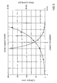
- FIG. 5 is a graphical illustration of the flow characteristic of the choke valve according to the invention, showing the flow Q in L/min in continuous line and the drag coefficient ⁇ in dotted line as a function of the length movement in mm of the throttling piston.
- FIG. 1 there is shown a schematic illustration of a flow regulating apparatus according to the present invention, including a housing 1 accommodating two choke valves 20 , 30 arranged in side-by-side relationship and intended for use in a pneumatic balancing hoist (not shown).
- a choke valve is a throttling device used to reduce a flow rate in a flow line.
- the left-hand choke valve 20 occupies a closed operating position
- the right-hand choke valve 30 occupies a partially open operating position.
- the choke valves 20 , 30 are of an identical construction, it will be understood by persons skilled in the art that a description of one of the choke valves is equally applicable to the other choke valve.
- Each choke valve 20 , 30 has an inlet port 2 and an outlet port 3 for a pressure fluid, e.g., compressed air.
- a fluid passageway or choke channel 4 fluidly connects the inlet port 2 and the outlet port 3 .
- Disposed in the choke channel 4 between the inlet and outlet ports 2 , 3 is a throttling piston 5 for movement in longitudinal direction between an initial position, in which the choke valve occupies the closed operating position (choke valve 20 in the exemplified illustration of FIG. 1 ), and an end position, in which the choke valve occupies the partially open operating position (choke valve 30 in the exemplified illustration of FIG. 1 ).
- the throttling piston 5 is essentially a metal cylinder having a central area formed with a radial taper 6 .
- the choke channel 4 is formed as an internal cylinder corresponding to the throttling piston 5 and thus is configured as cylindrical hollow space.
- Each of the choke valves 20 , 30 has one end (the upper end here, as viewed in FIG. 1) which juts out of the housing 1 to form an actuating member 13 to allow a user's thumb to operate the choke valves 20 , 30 and to thereby control a volume flow of the pressure fluid between the inlet port 2 and the outlet port 3 via an overflow passage (annular flow gap) 8 defined by the taper 6 and the choke channel 4 .
- the cross section of the overflow passage 8 is dependent on the axial position of the throttling piston 5 .
- the overflow passage 8 is depicted in open state to allow a fluid flow between the inlet and outlet ports 2 , 3
- FIG. 2 b shows the overflow passage 8 in closed state so that the fluid communication between the inlet and outlet ports 2 , 3 is cut.
- a sealing ring 8 a of the throttling piston 5 abuts against a shoulder 8 b of the housing 1 , as shown in particular in FIG. 2 b , to cut the fluid communication between the inlet and outlet ports 2 , 3 .
- each throttling piston 5 is supported by the housing 1 via a spring element 7 which loads the throttling piston 5 to seek the initial position.
- FIG. 4 there is shown an enlarged detailed cutaway view of the area encircled C of the throttling piston 5 of FIG. 3, to more clearly illustrate the midsection of the throttling piston.
- the throttling piston 5 has three distinct controlling length portions 9 a , 9 b , 9 c .
- the leading or starting length portion 9 a has a cylindrical configuration and is defined by an outer diameter which is smaller than an inner diameter of the choke channel 4 to thereby form an annular gap 10 (FIG. 1) which is determinative for the volume flow of pressure fluid as a consequence of its effective length.
- the overflow passage 8 may be considered as a residual overflow passage.
- the length portion 9 a terminates in the central length portion 9 b , which includes the initial zone of the taper 6 .
- the overflow cross section of the overflow passage 8 increases progressively and thus becomes greater superproportionally in dependence on the longitudinal displacement of the throttling piston 5 .
- FIG. 5 is a graphical illustration of the flow characteristic line of the choke valve according to the invention, showing the flow Q in L/min in continuous line and the drag coefficient ⁇ in dotted line as a function of the length movement in mm of the throttling piston 5 .
- the central length portion 9 b terminates in an end portion 9 c which has a conical configuration with a steep cone angle in comparison to the inclination of the central portion 9 b .
- a sensitive control of the balancing hoist is no longer required. It is only relevant to exploit the pressure drop between the inlet and outlet ports 2 , 3 in an optimal manner in order to attain a high load velocity.
- the configuration of the throttling piston 5 with the three length portions 9 a , 9 b , 9 c ensures a precise control of the hoist as a result of the continuous progressive increase of the overflow cross section.
Landscapes
- Engineering & Computer Science (AREA)
- General Engineering & Computer Science (AREA)
- Mechanical Engineering (AREA)
- Lift Valve (AREA)
- Safety Valves (AREA)
- Sliding Valves (AREA)
- Flow Control (AREA)
- Magnetically Actuated Valves (AREA)
- Electrically Driven Valve-Operating Means (AREA)
- Temperature-Responsive Valves (AREA)
Applications Claiming Priority (3)
| Application Number | Priority Date | Filing Date | Title |
|---|---|---|---|
| DE10134972.6-14 | 2001-07-24 | ||
| DE10134972 | 2001-07-24 | ||
| DE10134972A DE10134972A1 (de) | 2001-07-24 | 2001-07-24 | Durchlassventil für Strömungsmedium, insbesondere ein pneumatisches Drosselventil |
Publications (2)
| Publication Number | Publication Date |
|---|---|
| US20030020036A1 US20030020036A1 (en) | 2003-01-30 |
| US6802487B2 true US6802487B2 (en) | 2004-10-12 |
Family
ID=7692233
Family Applications (1)
| Application Number | Title | Priority Date | Filing Date |
|---|---|---|---|
| US10/202,146 Expired - Fee Related US6802487B2 (en) | 2001-07-24 | 2002-07-24 | Flow regulating apparatus for a fluid, in particular a pneumatic choke valve |
Country Status (6)
| Country | Link |
|---|---|
| US (1) | US6802487B2 (ja) |
| EP (1) | EP1279873B1 (ja) |
| JP (1) | JP2003156156A (ja) |
| AT (1) | ATE282786T1 (ja) |
| DE (2) | DE10134972A1 (ja) |
| ES (1) | ES2233771T3 (ja) |
Cited By (6)
| Publication number | Priority date | Publication date | Assignee | Title |
|---|---|---|---|---|
| US8083936B1 (en) * | 2008-03-03 | 2011-12-27 | Robert Walker | Reducing waste water in reverse osmosis residential drinking water systems |
| US20130145734A1 (en) * | 2011-12-08 | 2013-06-13 | Taechullndustrial Co., Ltd. | Drain valve apparatus and air separator thereof |
| US20130145733A1 (en) * | 2011-12-08 | 2013-06-13 | Taechul Industrial Co., Ltd. | Drain valve apparatus and air separator thereof |
| US20160208945A1 (en) * | 2015-01-19 | 2016-07-21 | Moen Incorporated | Electronic plumbing fixture fitting with electronic valve inculding piston and seat |
| US20160327164A1 (en) * | 2014-01-07 | 2016-11-10 | Intelligent Energy Limited | Valve assembly |
| US10456748B2 (en) | 2015-07-31 | 2019-10-29 | Ecowater Systems Llc | Variable drain flow restrictor |
Families Citing this family (6)
| Publication number | Priority date | Publication date | Assignee | Title |
|---|---|---|---|---|
| US20060027261A1 (en) * | 2004-08-04 | 2006-02-09 | Plevich Chuck W | Method for repair of regulator poppet and seat |
| DE102007025059B4 (de) | 2007-05-29 | 2018-02-01 | Konecranes Lifting Systems Gmbh | Pneumatische Steuereinrichtung für ein Drucklufthebezeug |
| EP2396577A2 (en) * | 2009-02-10 | 2011-12-21 | Norgren GmbH | Variable flow poppet valve |
| US9538299B2 (en) | 2009-08-31 | 2017-01-03 | Hewlett-Packard Development Company, L.P. | Acoustic echo cancellation (AEC) with conferencing environment templates (CETs) |
| US10070990B2 (en) | 2011-12-08 | 2018-09-11 | Alcon Research, Ltd. | Optimized pneumatic drive lines |
| DE102018102397A1 (de) | 2018-02-02 | 2019-08-08 | J.D. Neuhaus Holding Gmbh & Co. Kg | Steuerventilanordnung zur indirekten pneumatischen Steuerung |
Citations (7)
| Publication number | Priority date | Publication date | Assignee | Title |
|---|---|---|---|---|
| US1863712A (en) | 1930-07-14 | 1932-06-21 | Albert H Byfield | Heating system |
| US2904305A (en) | 1957-07-11 | 1959-09-15 | Milton A Novotny | Discharge control apparatus for powder fire extinguisher |
| GB988894A (en) | 1962-11-09 | 1965-04-14 | Damic Controls Ltd | Improvements in fluid control valves |
| GB992613A (en) | 1962-08-02 | 1965-05-19 | Messer Adolf Gmbh | A fluid flow control valve |
| US3472481A (en) * | 1965-10-22 | 1969-10-14 | Air Reduction | Self-aligning valve closure |
| DE3342405C2 (ja) | 1983-11-24 | 1987-05-14 | Bochumer Eisenhuette Heintzmann Gmbh & Co Kg, 4630 Bochum, De | |
| DE19932982A1 (de) | 1999-07-14 | 2001-01-25 | Festo Ag & Co | Drosselventil |
Family Cites Families (3)
| Publication number | Priority date | Publication date | Assignee | Title |
|---|---|---|---|---|
| JPS61286602A (ja) * | 1985-06-12 | 1986-12-17 | Junkosha Co Ltd | 流量制御弁 |
| JPH10160034A (ja) * | 1996-11-22 | 1998-06-16 | Nok Corp | ニードルバルブ |
| JP2000249233A (ja) * | 1999-02-26 | 2000-09-12 | Kitz Corp | 流量調整式ニードル弁 |
-
2001
- 2001-07-24 DE DE10134972A patent/DE10134972A1/de not_active Ceased
-
2002
- 2002-07-22 ES ES02090274T patent/ES2233771T3/es not_active Expired - Lifetime
- 2002-07-22 JP JP2002212311A patent/JP2003156156A/ja active Pending
- 2002-07-22 EP EP02090274A patent/EP1279873B1/de not_active Expired - Lifetime
- 2002-07-22 DE DE50201550T patent/DE50201550D1/de not_active Expired - Lifetime
- 2002-07-22 AT AT02090274T patent/ATE282786T1/de not_active IP Right Cessation
- 2002-07-24 US US10/202,146 patent/US6802487B2/en not_active Expired - Fee Related
Patent Citations (7)
| Publication number | Priority date | Publication date | Assignee | Title |
|---|---|---|---|---|
| US1863712A (en) | 1930-07-14 | 1932-06-21 | Albert H Byfield | Heating system |
| US2904305A (en) | 1957-07-11 | 1959-09-15 | Milton A Novotny | Discharge control apparatus for powder fire extinguisher |
| GB992613A (en) | 1962-08-02 | 1965-05-19 | Messer Adolf Gmbh | A fluid flow control valve |
| GB988894A (en) | 1962-11-09 | 1965-04-14 | Damic Controls Ltd | Improvements in fluid control valves |
| US3472481A (en) * | 1965-10-22 | 1969-10-14 | Air Reduction | Self-aligning valve closure |
| DE3342405C2 (ja) | 1983-11-24 | 1987-05-14 | Bochumer Eisenhuette Heintzmann Gmbh & Co Kg, 4630 Bochum, De | |
| DE19932982A1 (de) | 1999-07-14 | 2001-01-25 | Festo Ag & Co | Drosselventil |
Cited By (12)
| Publication number | Priority date | Publication date | Assignee | Title |
|---|---|---|---|---|
| US8083936B1 (en) * | 2008-03-03 | 2011-12-27 | Robert Walker | Reducing waste water in reverse osmosis residential drinking water systems |
| US20130145734A1 (en) * | 2011-12-08 | 2013-06-13 | Taechullndustrial Co., Ltd. | Drain valve apparatus and air separator thereof |
| US20130145733A1 (en) * | 2011-12-08 | 2013-06-13 | Taechul Industrial Co., Ltd. | Drain valve apparatus and air separator thereof |
| US20160327164A1 (en) * | 2014-01-07 | 2016-11-10 | Intelligent Energy Limited | Valve assembly |
| US10145477B2 (en) * | 2014-01-07 | 2018-12-04 | Intelligent Energy Limited | Valve assembly |
| US20160208945A1 (en) * | 2015-01-19 | 2016-07-21 | Moen Incorporated | Electronic plumbing fixture fitting with electronic valve inculding piston and seat |
| USD782617S1 (en) | 2015-01-19 | 2017-03-28 | Moen Incorporated | Valve housing connector |
| USD783779S1 (en) | 2015-01-19 | 2017-04-11 | Moen Incorporated | Valve housing connectors |
| US10392786B2 (en) * | 2015-01-19 | 2019-08-27 | Moen Incorporated | Electronic plumbing fixture fitting with electronic valve including piston and seat |
| US10456748B2 (en) | 2015-07-31 | 2019-10-29 | Ecowater Systems Llc | Variable drain flow restrictor |
| US10874987B2 (en) | 2015-07-31 | 2020-12-29 | Ecowater Systems Llc | Variable drain flow restrictor |
| US11583806B2 (en) | 2015-07-31 | 2023-02-21 | Ecowater Systems Llc | Variable drain flow restrictor |
Also Published As
| Publication number | Publication date |
|---|---|
| DE10134972A1 (de) | 2003-02-20 |
| ATE282786T1 (de) | 2004-12-15 |
| JP2003156156A (ja) | 2003-05-30 |
| EP1279873B1 (de) | 2004-11-17 |
| US20030020036A1 (en) | 2003-01-30 |
| DE50201550D1 (de) | 2004-12-23 |
| EP1279873A1 (de) | 2003-01-29 |
| ES2233771T3 (es) | 2005-06-16 |
Similar Documents
| Publication | Publication Date | Title |
|---|---|---|
| US6802487B2 (en) | Flow regulating apparatus for a fluid, in particular a pneumatic choke valve | |
| AU2005238895B2 (en) | Asymmetric volume booster arrangement for valve actuators | |
| US6554014B2 (en) | Proportional pilot operated directional valve | |
| US5086808A (en) | Balanced sleeve control choke | |
| US10598288B2 (en) | Cascaded controllable fluid control valve and valve trim for a fluid control valve | |
| AU2002352704B2 (en) | Valve plug | |
| EP2375083B1 (en) | Relief valve | |
| US20040256012A1 (en) | Pressure regulating valve in particular proportional pressure regulating valve | |
| WO2007046379A1 (ja) | ケージ弁 | |
| EP1544526B1 (en) | Fluid controller | |
| CN101059140B (zh) | 线性驱动装置 | |
| US11307599B2 (en) | Device and valve for flow force compensation | |
| US7789373B2 (en) | Ball poppet valve with contoured control stem | |
| WO2015126634A1 (en) | Balanced regulator having a balanced trim including a variable pressure sense area | |
| US5669422A (en) | Slow start valve | |
| US11137081B2 (en) | Control valve | |
| US5675969A (en) | Exhaust gas control device in an internal combustion engine | |
| US4254798A (en) | Directional control valve | |
| CN112204236A (zh) | 长度可调的连杆、往复活塞式发动机以及车辆 | |
| US20030102031A1 (en) | Relief valve | |
| JP3996132B2 (ja) | 液圧シリンダのクッション装置 | |
| EP3553324B1 (en) | Valve and hydraulic system with the same | |
| KR960008272B1 (ko) | 속도제어기 | |
| US11047400B2 (en) | Fluid pressure control device | |
| US20070290423A1 (en) | Telescopic Pneumatic Device |
Legal Events
| Date | Code | Title | Description |
|---|---|---|---|
| AS | Assignment |
Owner name: DEMAG CRANES & COMPONENTS GMBH, GERMANY Free format text: ASSIGNMENT OF ASSIGNORS INTEREST;ASSIGNORS:HEUN, JURGEN;LOBEL, MARKUS;FUHRMANN, JORG;REEL/FRAME:013136/0486;SIGNING DATES FROM 20020718 TO 20020719 |
|
| FEPP | Fee payment procedure |
Free format text: PAYOR NUMBER ASSIGNED (ORIGINAL EVENT CODE: ASPN); ENTITY STATUS OF PATENT OWNER: LARGE ENTITY |
|
| CC | Certificate of correction | ||
| FPAY | Fee payment |
Year of fee payment: 4 |
|
| FPAY | Fee payment |
Year of fee payment: 8 |
|
| AS | Assignment |
Owner name: TEREX MHPS GMBH, GERMANY Free format text: MERGER AND CHANGE OF NAME;ASSIGNORS:DEMAG CRANES & COMPONENTS GMBH;TEREX MHPS GMBH;REEL/FRAME:034703/0915 Effective date: 20140630 |
|
| REMI | Maintenance fee reminder mailed | ||
| LAPS | Lapse for failure to pay maintenance fees | ||
| STCH | Information on status: patent discontinuation |
Free format text: PATENT EXPIRED DUE TO NONPAYMENT OF MAINTENANCE FEES UNDER 37 CFR 1.362 |
|
| FP | Lapsed due to failure to pay maintenance fee |
Effective date: 20161012 |