US6772824B1 - Cooling system for vehicle - Google Patents
Cooling system for vehicle Download PDFInfo
- Publication number
- US6772824B1 US6772824B1 US09/654,136 US65413600A US6772824B1 US 6772824 B1 US6772824 B1 US 6772824B1 US 65413600 A US65413600 A US 65413600A US 6772824 B1 US6772824 B1 US 6772824B1
- Authority
- US
- United States
- Prior art keywords
- cooler
- case
- fan
- cooling system
- accommodated
- Prior art date
- Legal status (The legal status is an assumption and is not a legal conclusion. Google has not performed a legal analysis and makes no representation as to the accuracy of the status listed.)
- Expired - Fee Related, expires
Links
Images


Classifications
-
- B—PERFORMING OPERATIONS; TRANSPORTING
- B60—VEHICLES IN GENERAL
- B60K—ARRANGEMENT OR MOUNTING OF PROPULSION UNITS OR OF TRANSMISSIONS IN VEHICLES; ARRANGEMENT OR MOUNTING OF PLURAL DIVERSE PRIME-MOVERS IN VEHICLES; AUXILIARY DRIVES FOR VEHICLES; INSTRUMENTATION OR DASHBOARDS FOR VEHICLES; ARRANGEMENTS IN CONNECTION WITH COOLING, AIR INTAKE, GAS EXHAUST OR FUEL SUPPLY OF PROPULSION UNITS IN VEHICLES
- B60K11/00—Arrangement in connection with cooling of propulsion units
- B60K11/02—Arrangement in connection with cooling of propulsion units with liquid cooling
- B60K11/04—Arrangement or mounting of radiators, radiator shutters, or radiator blinds
-
- B—PERFORMING OPERATIONS; TRANSPORTING
- B60—VEHICLES IN GENERAL
- B60K—ARRANGEMENT OR MOUNTING OF PROPULSION UNITS OR OF TRANSMISSIONS IN VEHICLES; ARRANGEMENT OR MOUNTING OF PLURAL DIVERSE PRIME-MOVERS IN VEHICLES; AUXILIARY DRIVES FOR VEHICLES; INSTRUMENTATION OR DASHBOARDS FOR VEHICLES; ARRANGEMENTS IN CONNECTION WITH COOLING, AIR INTAKE, GAS EXHAUST OR FUEL SUPPLY OF PROPULSION UNITS IN VEHICLES
- B60K11/00—Arrangement in connection with cooling of propulsion units
- B60K11/02—Arrangement in connection with cooling of propulsion units with liquid cooling
Definitions
- This invention relates to a vehicle body mounting structure for a cooler such as an oil cooler which is used together with a cooling fan.
- FIG. 7 shows a conventional vehicle body mounting structure for a cooler and a cooling fan.
- a cooler 100 has mounting portions 101 on the left and right of an upper portion thereof, and lower ends of suspending brackets 102 are attached to the mounting portions 101 by means of bolts 103 with mounting rubber members 104 of the bush type interposed therebetween while upper ends of the suspending brackets 102 are attached to stays 107 provided on a vehicle body frame 106 with bolts 105 .
- a cooling fan 110 for forced cooling is disposed rearwardly in the proximity of the cooler 100 and is accommodated in a cylindrical shroud 111 .
- Suspending brackets 114 are each attached at one end thereof by means of bolts 113 to a boss 112 provided on the shroud 111 .
- the suspending brackets 114 are attached at the other ends thereof to stays 115 provided separately from the stays 107 on the vehicle body frame 106 by means of bolts 116 . Further, it is known to mount a cooling fan directly on the rear face of a radiator by use of rubber mounts for the cooling fan (for example, Japanese Utility Model Laid-open No. Sho 54-56820) Also it is known to mount a frame, in which a radiator and so forth are accommodated, on the vehicle body side (refer to, for example, Japanese Utility Model Publication No. Sho 62-35675 and Japanese Patent Laid-open No. Hei 10-1884)
- a cooling system for a vehicle which includes a cooler and a cooling fan disposed rearwardly in the proximity of the cooler and wherein the cooler and the cooling fan are supported on a vehicle body is characterized in that the cooler and the cooling fan are accommodated in a unitary case to form the cooler and the cooling fan into a unit.
- a second aspect of the present invention is characterized in that, in the first aspect of the present invention, the case is divided forwardly and rearwardly into a front half portion side in which the cooler is accommodated and a rear half portion side in which the cooling fan is accommodated, and the front half portion side and the rear half portion side are put together from forwardly and backwardly and connected to and integrated with each other.
- a third aspect of the present invention is characterized in that, in the second aspect of the present invention, a vehicle body mounting portion is formed integrally on either one of the front half portion side and the rear half portion side of the case.
- a fourth aspect of the present invention is characterized in that, in the first aspect of the present invention, when the cooler is accommodated into the case, a resilient member is interposed in a non-coupling state between the cooler and an inner face of the case.
- a fifth aspect of the present invention is characterized in that, in the first aspect of the present invention, the cooler is an oil cooler.
- the cooler and the cooling fan are accommodated in the same case to form the cooler and the cooling fan into a unit, the cooler and the cooling fan can be handled as a single apparatus and the cooler and the cooling fan need not be mounted separately from each other on the vehicle body, the number of parts and the number of mounting man-hours can be reduced. Further, irrespective of whether the cooler is large or small, the cooling fan can be integrated with the cooler.
- the cooler since the case is divided forwardly and rearwardly into the front half portion side and the rear half portion side, if the cooler is accommodated into the front half portion side and the cooling fan is accommodated into the rear half portion side and thereafter the front half portion side and the rear half portion side are put together from forwardly and backwardly and coupled to each other by means of fastening screws or the like, then they can be formed into a unit simply.
- the third aspect of the present invention only if a vehicle body mounting portion is provided on either one of the front half portion side and the rear half portion side, mounting onto the vehicle body is allowed, and the number of mounting portions and the number of mounting man-hours can be reduced.
- the structure wherein the cooler is accommodated and held in the case is adopted, only it is required to interpose a mount rubber member merely in a non-coupling state between the cooler and the case. Consequently, the necessity to use a rubber mounting structure formed as a bushing as in the prior art is eliminated, and the vibration-preventing structure is simplified and the number of parts and the number of mounting man-hours can be reduced.
- the cooler is an oil cooler, in spite of the structure which does not have a frame on which a cooling fan can be mounted, the oil cooler and the cooling fan can be formed as a unitary member.
- FIG. 1 is a side elevational view of essential part of a vehicle body to which an embodiment is applied;
- FIG. 2 is a side elevational view of a four-wheeled vehicle to which the embodiment is applied;
- FIG. 3 is a side elevational view of a principal portion of the vehicle body of the four-wheeled vehicle
- FIG. 4 is a perspective view of a similar portion
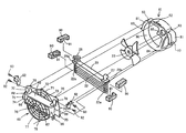
- FIG. 5 is an exploded view of a cooler of the embodiment
- FIG. 6 is an enlarged sectional view of essential part of the cooler.
- FIG. 7 is an exploded view of a conventional example.
- a pair of front wheels 2 and a pair of rear wheels 3 each formed from a low pressure balloon tire are supported on the left and right at forward and rearward portions of a vehicle body frame l, respectively, such that they are driven by a power unit 4 carried at a central portion of the vehicle body frame 1 , and are suspended by front shock absorbers 5 and rear shock absorbers 6 .
- a front fender 7 is provided together with a sub fender 8 and a rear fender 9 .
- a front panel 10 is provided together with a steering shaft 11 , a handle bar 12 , a fuel tank 13 , a saddle type seat 14 , a rear panel 15 , a cooling unit 16 , and a muffler 17 .
- an air cleaner 18 is provided together with a snorkel type duct 19 and a carburetor 20 .
- the vehicle body frame 1 includes a pair of left and right upper pipes 30 that extend substantially in parallel and linearly in the forward and backward directions, a pair of left and right front pipes 31 extend in the upward and downward directions from the front end portions of the upper pipes 30 , a pair of left and right lower pipes 32 extend rearwardly from lower end portions of the front pipes 31 , and a pair of left and right center pipes 33 extend upwardly from rear end portions of the lower pipes 32 and connecting to rather rear positions of intermediate portions of the upper pipes 30 .
- the vehicle body frame 1 further includes a pair of left and right reinforcement pipes 34 connect obliquely from front end portions of upper pipes 30 to front half side portions of the lower pipes 32 , a pair of left and right intermediate pipes 35 connect intermediate portions of the reinforcement pipes 34 and the front pipes 31 to each other in the forward and backward directions, and pairs of reinforcement pipes 36 and 37 obliquely connect intermediate portions of the center pipes 33 and front and rear positions of the upper pipes 30 on the opposite sides of the connection points of the center pipes 33 to the upper pipes 30 .
- a cross member 40 , cross pipes 41 and 42 , cross members 43 , 44 , 45 and 46 , and so forth extend, thereby forming the vehicle body frame 1 wherein all of the members are connected integrally.
- the cross member 40 extends between front end portions of the upper pipes 30 .
- the cross member 40 and the cross pipe 41 which is disposed rearwardly in parallel to the cross member 40 , are connected forwardly and backwardly to each other by head portion pipes 47 which have an inverted V-shape in the side elevation.
- the steering shaft 11 is supported at an upper portion thereof for rotation by a stay 48 provided at top portions of the head portion pipes 47 .
- a lower end portion of the steering shaft 11 is supported for rotation by a bearing member provided on the intermediate pipes 35 .
- upper end portions of the front cushions 5 are supported at the opposite left and right ends of the cross member 40 , and lower end portions of the front cushions 5 are mounted on upper arms which form front wheel suspensions of the double wishbone type (not shown).
- the upper arms are supported swingably on the intermediate pipes 35 , and lower arms paired with the upper arms are supported swingably at front end portions of the lower pipes 32 .
- Pivot plates 50 are provided at corner portions of lower portions of the center pipes 33 and the rear ends of the lower pipes 32 , and front end portions of rear swing arms 51 are supported swingably on the pivot plates 50 .
- the rear swing arms 51 accommodate a drive shaft which forms a rear wheel driving mechanism.
- the upper pipes 30 extend further rearwardly from the connection portions thereof to the center pipes 33 , and upper end portions of the rear cushions 6 are supported by stays 52 provided at the extending portions of the upper pipes 30 while the muffler 17 is supported by different stays 53 .
- An exhaust pipe 21 having a rear end portion connected to the muffler 17 extends substantially linearly forwardly and is bent substantially in a U shape at a front end portion thereof, and is connected to an exhaust port provided in a cylinder head of the power unit 4 . Further, the cooling unit 16 is suspended and supported on the upper pipes 30 forwardly of the power unit 4 .
- the cooling unit 16 includes an oil cooler 22 and a cooling fan 23 which are formed as a unitary member.
- a motor 24 is provided for the cooling unit 16 while hoses 25 and 26 are connected to the power unit 4 .
- steps 54 extending outwardly sidewards are provided at portions of the left and right lower pipes 32 at which the power unit 4 is mounted.
- the steps 54 project outwardly sidewards from the lower pipes 32
- step frames 55 connect the ends of the steps 54 and the lower pipes 32 in a bent form.
- the sub fenders 8 (the sub fender 8 on the right side of the vehicle body is not shown) are placed on and attached to the step frames 55 .
- the cooling unit 16 is constructed such that the oil cooler 22 and the cooling fan 23 are accommodated in a single case formed from a lid 60 and a fan cover 61 which are integrated with each other.
- the cooling unit 16 is suspended and supported by fastening the same by means of bolts to stays 63 welded to side faces of the upper pipes 30 through suspending brackets 62 .
- the lid 60 is molded suitably of a synthetic resin and has an accommodation portion 65 which is a recessed portion which can accommodate the oil cooler 22 .
- a large number of air vent holes 67 are formed in a front wall 66
- joint holes 69 and suspending projections 70 are formed integrally on the left and right of an upper wall 68 .
- the suspending projections 70 project upwardly in an opposing relationship to each other from the opposite left and right end portions of the upper wall 68 .
- the upper side of the lid 60 than the upper wall 68 forms a substantially arcuate upward projection 71
- a mounting projection 72 having a through-hole for a screw formed therein is formed integrally at a top portion of the upward projection 71
- a pair of mounting projections 75 are provided integrally on the opposite left and right sides of the upward projection 71 with respect to the mounting projection 72 .
- Air vent holes 73 are formed also in the upward projection 71 .
- a plurality of mounting projections 75 similar to the mounting projection 72 are formed integrally on the left and right sidewardly projecting portions 74 .
- the lower side of the lid 60 and the accommodation portion 65 forms a substantially arcuate lower projection 76 , and air vent holes 77 are formed in the lower projection 76 .
- a mounting projection 78 similar to the mounting projection 72 is formed integrally at a lowermost portion of the lower projection 76 .
- the fan cover 61 is a member molded suitably of a synthetic resin similarly, and includes a circular fan accommodation portion 80 for accommodating the cooling fan 23 and a pair of projecting portions 81 integrally projecting leftwardly and rightwardly from the fan accommodation portion 80 .
- the fan accommodation portion 80 coincides at an outer periphery thereof with an outer periphery of the circular portion of the lid 60 described above, and bosses 82 and 84 provided at a top portion and a lowermost portion of the fan accommodation portion 80 coincide with the mounting projections 72 and 78 when the fan cover 61 is mounted on the lid 60 .
- a hub portion 85 through which a rotary shaft of the cooling fan 23 extends is provided integrally on the rear face side of the fan accommodation portion 80 , and the driving motor 24 is mounted on the hub portion 85 such that the cooling fan 23 can be accommodated and supported for rotation in the fan accommodation portion 80 .
- the projecting portions 81 overlap, when the fan cover 61 is mounted on the lid 60 , with the sidewardly projecting portions 74 , and bosses 83 provided at edge portions of the projecting portions 81 coincide with the mounting projections 75 of the corresponding sidewardly projecting portions 74 .
- the bosses 82 , 83 and 84 are formed integrally with the fan cover 61 and have insert nuts integrated therewith in advance.
- the rear face sides of the projecting portions 81 define spaces which are open to the rear and are communicated with a space above the upper wall 68 through the joint holes 69 , and front end portions of the hoses 25 , 26 are accommodated in the spaces while the hoses 25 , 26 are connected to joints 27 , 28 of the oil cooler 22 , which are hereinafter described, through the joint holes 69 .
- the oil cooler 22 has a tank section 29 which has the joints 27 , 28 provided at the opposite left and right end sides, and projecting end portions 29 a extending in the leftward and rightward directions are provided at the opposite end portions of the tank section 29 .
- the joints 27 , 28 project upwardly of the upper wall 68 and forwardly of the upward projection 71 through the left and right joint holes 69 when the oil cooler 22 is accommodated in the accommodation portion 65 .
- the oil cooler 22 accommodated in the accommodation portion 65 has damper rubber members 90 interposed at upper, lower and left, right corners thereof
- the damper rubber members 90 are not coupled to the oil cooler 22 but are merely pressed against the four corners in the accommodation portion 65 thereby to resiliently support the projecting end portions 29 a on the left and right at upper portions of the oil cooler 22 and left and right lower side end portions 22 a (FIG. 6 ).
- a recessed portion 91 is provided for fitting with any of the projecting end portions 29 a and the lower side end portions 22 a which are upper, lower and left, right corner portions of the oil cooler 22 .
- the dimension of the oil cooler 22 in the upward and downward directions is smaller than the diameter of the cooling fan 23 and the oil cooler 22 does not have, on the left and right and lower sides, a frame structure by which the cooling fan 23 can be mounted. Meanwhile, bolts 92 and 93 are provided for attaching any of the suspending brackets 62 .
- the oil cooler 22 is accommodated into the accommodation portion 65 of the lid 60 , and the lid 60 is placed together with the fan cover 61 having the cooling fan 23 accommodated in the fan accommodation portion 80 thereof in advance.
- the mounting projection 72 and the boss 82 , the mounting projections 75 and the bosses 83 , and the mounting projection 78 and the boss 84 are aligned with each other, and the lid 60 and the fan cover 61 are fastened to each other by screws (not shown) from the lid 60 side.
- the cooling unit 16 wherein the lid 60 and the fan cover 61 are coupled to and integrated with each other and the oil cooler 22 and the cooling fan 23 are accommodated in and supported on the inside of the lid 60 and the fan cover 61 is obtained.
- This cooling unit 16 is suspended and supported on the upper pipes 30 only by attaching the suspending projections 70 provided at the upper portion of the lid 60 to the lower portion of the suspending brackets 62 by means of the bolts 92 and fastening the upper portion of the suspending brackets 62 to the stays 63 by means of the bolts 93 . Consequently, the fan cover 61 side need not be attached to the upper pipes 30 separately from the lid 60 .
- the oil cooler 22 is resiliently supported on the lid 60 only by accommodating the oil cooler 22 into the accommodation portion 65 of the lid 60 with the damper rubber members 90 interposed therebetween, a non-coupled state wherein the damper rubber members 90 are not attached to the oil cooler 22 by direct fastening or the like can be established, and the necessity to use a rubber mounting structure using bolts and bushings as in the prior art is eliminated. Consequently, the vibration preventing structure can be simplified and reduction of the number of parts and the mounting man-hours can be achieved.
- the dimension of the oil cooler 22 in the upward and downward directions is smaller than the diameter of the cooling fan 23 and besides does not have a frame structure on the left, right and lower sides, although it is impossible to directly mount the cooling fan 23 , such oil cooler 22 and cooling fan 23 can be readily, integrally formed as a unit. Besides, even if the sizes of the oil cooler 22 and the cooling fan 23 vary differently, they can be combined with each other, and consequently, the degree of freedom in combination is high.
- the present invention is not limited to the embodiment described above and variable modifications and applications are possible within the range within which the essence of the invention is common.
- the suspending projections 70 may be formed on an upper wall of the fan cover 61 , instead of on the upper wall 68 of lid 60 .
- the cooler is not limited to the oil cooler 22 but may be a radiator, and besides, the dimension of it in the upward and downward directions may be greater than the cooling fan 23 .
- a suitable resilient member such as a metal spring or elastomer can be used in place of the damper rubber members 90 .
Landscapes
- Engineering & Computer Science (AREA)
- Chemical & Material Sciences (AREA)
- Combustion & Propulsion (AREA)
- Transportation (AREA)
- Mechanical Engineering (AREA)
- Cooling, Air Intake And Gas Exhaust, And Fuel Tank Arrangements In Propulsion Units (AREA)
Applications Claiming Priority (2)
| Application Number | Priority Date | Filing Date | Title |
|---|---|---|---|
| JP11-250971 | 1999-09-03 | ||
| JP25097199A JP4400803B2 (ja) | 1999-09-03 | 1999-09-03 | 車両用冷却装置 |
Publications (1)
| Publication Number | Publication Date |
|---|---|
| US6772824B1 true US6772824B1 (en) | 2004-08-10 |
Family
ID=17215761
Family Applications (1)
| Application Number | Title | Priority Date | Filing Date |
|---|---|---|---|
| US09/654,136 Expired - Fee Related US6772824B1 (en) | 1999-09-03 | 2000-09-01 | Cooling system for vehicle |
Country Status (2)
| Country | Link |
|---|---|
| US (1) | US6772824B1 (ja) |
| JP (1) | JP4400803B2 (ja) |
Cited By (20)
| Publication number | Priority date | Publication date | Assignee | Title |
|---|---|---|---|---|
| US20050039719A1 (en) * | 2003-08-21 | 2005-02-24 | Moss Marlon Euyvon | Method and apparatus for efficiently cooling motocycle engines |
| US20060040154A1 (en) * | 2004-08-20 | 2006-02-23 | Honda Motor Co., Ltd. | Fuel-cell vehicle |
| US20060065454A1 (en) * | 2004-09-29 | 2006-03-30 | Honda Motor Co., Ltd. | Body frame of saddle-ride type vehicle |
| US20060278451A1 (en) * | 2005-06-10 | 2006-12-14 | Honda Motor Co., Ltd. | Vehicular radiator unit |
| US20070277752A1 (en) * | 2006-06-05 | 2007-12-06 | Deere & Company, A Delaware Corporation | Shroud assembly |
| US20080236918A1 (en) * | 2007-03-30 | 2008-10-02 | Seiji Hanafusa | Saddle-ride type four-wheel vehicle |
| US20090152033A1 (en) * | 2007-12-14 | 2009-06-18 | Hyundai Motor Company | Structure for mounting radiator to front-end module carrier |
| US20090183867A1 (en) * | 2008-01-23 | 2009-07-23 | Compressor Systems Inc. | Varying ambient heat exchanger for a compressor |
| US20110189019A1 (en) * | 2010-02-01 | 2011-08-04 | Jason Scot Richardson | Shroud for rotating machine component |
| US20120132396A1 (en) * | 2010-11-29 | 2012-05-31 | Denso Corporation | Air conditioning system for vehicle |
| US9446809B2 (en) * | 2013-08-05 | 2016-09-20 | Richard Oneal Sallis | Frame covering device with air vents |
| US10247083B2 (en) * | 2017-08-22 | 2019-04-02 | Kawasaki Jukogyo Kabushiki Kaisha | Straddle vehicle and radiator air-guide device |
| US10371249B1 (en) | 2017-05-24 | 2019-08-06 | Indian Motorcycle International, LLC | Engine |
| US10589621B1 (en) | 2017-05-24 | 2020-03-17 | Indian Motorcycle International, LLC | Two-wheeled vehicle |
| US10655536B1 (en) | 2017-05-24 | 2020-05-19 | Indian Motorcycle International, LLC | Engine |
| US10946736B2 (en) * | 2018-06-05 | 2021-03-16 | Polaris Industries Inc. | All-terrain vehicle |
| US10960937B2 (en) | 2007-03-16 | 2021-03-30 | Polaris Industries Inc. | Vehicle |
| US11173808B2 (en) | 2016-12-22 | 2021-11-16 | Polaris Industies Inc. | Vehicle |
| US11260749B2 (en) * | 2016-09-26 | 2022-03-01 | Transportation Ip Holdings, Llc | Cooling control systems |
| US11413936B2 (en) * | 2016-11-18 | 2022-08-16 | Mitsubishi Heavy Industries Thermal Systems, Ltd. | Heat exchanger headers with buffer and damping materials |
Families Citing this family (4)
| Publication number | Priority date | Publication date | Assignee | Title |
|---|---|---|---|---|
| JP4400803B2 (ja) * | 1999-09-03 | 2010-01-20 | 本田技研工業株式会社 | 車両用冷却装置 |
| CN105649749A (zh) * | 2014-11-11 | 2016-06-08 | 上海申龙客车有限公司 | 一种可靠的电磁风扇固定支架 |
| JP6837425B2 (ja) * | 2017-12-27 | 2021-03-03 | 本田技研工業株式会社 | 鞍乗り型車両 |
| CN109532466A (zh) * | 2018-11-19 | 2019-03-29 | 郭建星 | 汽车散热器用固定防护装置 |
Citations (37)
| Publication number | Priority date | Publication date | Assignee | Title |
|---|---|---|---|---|
| US1840417A (en) * | 1930-03-19 | 1932-01-12 | Mcquay Radiator Corp | Frame and mounting for heat exchange units |
| US1988693A (en) * | 1931-12-21 | 1935-01-22 | Perfex Radiator Company | Heater |
| US2003045A (en) * | 1934-11-08 | 1935-05-28 | Goodrich Co B F | Hot water heater for automobiles |
| US2015231A (en) * | 1934-12-07 | 1935-09-24 | Mathew J Marty | Automobile heater |
| US2087160A (en) * | 1937-05-07 | 1937-07-13 | E A Lab Inc | Heater |
| US2118281A (en) * | 1935-08-09 | 1938-05-24 | Tropic Aire Inc | Automobile heater |
| US2238585A (en) * | 1940-04-04 | 1941-04-15 | Eaton Mfg Co | Automobile underseat air conditioning unit |
| US2278376A (en) * | 1937-10-08 | 1942-03-31 | Fred M Young | Unit heater |
| US2377094A (en) * | 1937-07-10 | 1945-05-29 | E A Lab Inc | Heat transfer device |
| US2623735A (en) * | 1948-12-16 | 1952-12-30 | E L Schofield Inc | Recirculating air heater |
| US2699323A (en) * | 1951-06-08 | 1955-01-11 | Bergstrom Mfg Co | Automotive heater |
| US2900172A (en) * | 1956-03-30 | 1959-08-18 | E L Schofield Inc | Heater for motor vehicles |
| US3258066A (en) * | 1964-03-10 | 1966-06-28 | Radiant Basehoard Panels Inc | Finned tube heating element |
| US3319708A (en) * | 1965-06-18 | 1967-05-16 | Embassy Ind Inc | Penetrable tract for finned heating unit with barbs |
| US3369595A (en) * | 1966-03-31 | 1968-02-20 | Embassy Ind Inc | Fin tube unit with protective corner plastic rails |
| US3858291A (en) * | 1972-01-31 | 1975-01-07 | Garrett Corp | Method of mounting a heat exchanger core |
| JPS5456820A (en) | 1977-10-15 | 1979-05-08 | Asahi Optical Co Ltd | Photographic lens barrel focusing device |
| JPS5713214A (en) * | 1980-06-30 | 1982-01-23 | Honda Motor Co Ltd | Cooling device for exhaust gas turbine of vehicle |
| US4315540A (en) * | 1979-05-04 | 1982-02-16 | Societe Anonyme Des Usines Chausson | Device for fixing a radiator into a vehicle particularly into a heavy-truck vehicle |
| JPS5733019A (en) * | 1980-08-04 | 1982-02-23 | Honda Motor Co Ltd | Radiator device in autobicycle |
| US4386735A (en) * | 1980-01-17 | 1983-06-07 | Klockner-Humboldt-Deutz Ag | Apparatus for heating an operator's cabin |
| JPS58185322A (ja) * | 1982-04-22 | 1983-10-29 | Honda Motor Co Ltd | 自動三輪車 |
| JPS59105918A (ja) * | 1982-12-09 | 1984-06-19 | Honda Motor Co Ltd | 自動二輪車における冷却フアンユニツトの取付構造 |
| US4461366A (en) * | 1981-09-18 | 1984-07-24 | Honda Motor Co., Ltd. | Frame for motorcycles |
| JPS59195098A (ja) * | 1983-04-19 | 1984-11-06 | Honda Motor Co Ltd | 車輌用放熱器 |
| JPS59197796A (ja) * | 1983-04-21 | 1984-11-09 | Honda Motor Co Ltd | 車輌用放熱器 |
| JPS59218319A (ja) * | 1983-05-13 | 1984-12-08 | Honda Motor Co Ltd | 自動二輪車用熱交換器支持構造 |
| JPS61122030A (ja) * | 1984-11-19 | 1986-06-10 | Honda Motor Co Ltd | 自動二輪車用エンジン冷却装置 |
| DE3446752A1 (de) * | 1984-12-21 | 1986-07-03 | Daimler-Benz Ag, 7000 Stuttgart | Halterung fuer einen kuehler, insbesondere oelkuehler an einem kraftfahrzeug |
| JPS6235675A (ja) | 1985-08-09 | 1987-02-16 | Sumitomo Electric Ind Ltd | 電界効果トランジスタ |
| JPS62101818A (ja) * | 1985-10-30 | 1987-05-12 | Honda Motor Co Ltd | 小型車両用ラジエタ−のシユラウド取付け構造 |
| JPS63106320A (ja) * | 1986-10-23 | 1988-05-11 | Honda Motor Co Ltd | ラジエ−タ装置 |
| JPH04262983A (ja) * | 1991-02-19 | 1992-09-18 | Suzuki Motor Corp | オートバイのオイルクーラー装置 |
| US5220973A (en) * | 1990-11-07 | 1993-06-22 | Dr. Ing. H.C.F. Porsche A.G. | Holding device for a cooler |
| JPH1018843A (ja) | 1996-06-28 | 1998-01-20 | Suzuki Motor Corp | ラジエータ取付構造 |
| JPH1191669A (ja) * | 1997-09-25 | 1999-04-06 | Honda Motor Co Ltd | ラジエータの取付構造 |
| JP2001071756A (ja) * | 1999-09-03 | 2001-03-21 | Honda Motor Co Ltd | 車両用冷却装置 |
-
1999
- 1999-09-03 JP JP25097199A patent/JP4400803B2/ja not_active Expired - Fee Related
-
2000
- 2000-09-01 US US09/654,136 patent/US6772824B1/en not_active Expired - Fee Related
Patent Citations (37)
| Publication number | Priority date | Publication date | Assignee | Title |
|---|---|---|---|---|
| US1840417A (en) * | 1930-03-19 | 1932-01-12 | Mcquay Radiator Corp | Frame and mounting for heat exchange units |
| US1988693A (en) * | 1931-12-21 | 1935-01-22 | Perfex Radiator Company | Heater |
| US2003045A (en) * | 1934-11-08 | 1935-05-28 | Goodrich Co B F | Hot water heater for automobiles |
| US2015231A (en) * | 1934-12-07 | 1935-09-24 | Mathew J Marty | Automobile heater |
| US2118281A (en) * | 1935-08-09 | 1938-05-24 | Tropic Aire Inc | Automobile heater |
| US2087160A (en) * | 1937-05-07 | 1937-07-13 | E A Lab Inc | Heater |
| US2377094A (en) * | 1937-07-10 | 1945-05-29 | E A Lab Inc | Heat transfer device |
| US2278376A (en) * | 1937-10-08 | 1942-03-31 | Fred M Young | Unit heater |
| US2238585A (en) * | 1940-04-04 | 1941-04-15 | Eaton Mfg Co | Automobile underseat air conditioning unit |
| US2623735A (en) * | 1948-12-16 | 1952-12-30 | E L Schofield Inc | Recirculating air heater |
| US2699323A (en) * | 1951-06-08 | 1955-01-11 | Bergstrom Mfg Co | Automotive heater |
| US2900172A (en) * | 1956-03-30 | 1959-08-18 | E L Schofield Inc | Heater for motor vehicles |
| US3258066A (en) * | 1964-03-10 | 1966-06-28 | Radiant Basehoard Panels Inc | Finned tube heating element |
| US3319708A (en) * | 1965-06-18 | 1967-05-16 | Embassy Ind Inc | Penetrable tract for finned heating unit with barbs |
| US3369595A (en) * | 1966-03-31 | 1968-02-20 | Embassy Ind Inc | Fin tube unit with protective corner plastic rails |
| US3858291A (en) * | 1972-01-31 | 1975-01-07 | Garrett Corp | Method of mounting a heat exchanger core |
| JPS5456820A (en) | 1977-10-15 | 1979-05-08 | Asahi Optical Co Ltd | Photographic lens barrel focusing device |
| US4315540A (en) * | 1979-05-04 | 1982-02-16 | Societe Anonyme Des Usines Chausson | Device for fixing a radiator into a vehicle particularly into a heavy-truck vehicle |
| US4386735A (en) * | 1980-01-17 | 1983-06-07 | Klockner-Humboldt-Deutz Ag | Apparatus for heating an operator's cabin |
| JPS5713214A (en) * | 1980-06-30 | 1982-01-23 | Honda Motor Co Ltd | Cooling device for exhaust gas turbine of vehicle |
| JPS5733019A (en) * | 1980-08-04 | 1982-02-23 | Honda Motor Co Ltd | Radiator device in autobicycle |
| US4461366A (en) * | 1981-09-18 | 1984-07-24 | Honda Motor Co., Ltd. | Frame for motorcycles |
| JPS58185322A (ja) * | 1982-04-22 | 1983-10-29 | Honda Motor Co Ltd | 自動三輪車 |
| JPS59105918A (ja) * | 1982-12-09 | 1984-06-19 | Honda Motor Co Ltd | 自動二輪車における冷却フアンユニツトの取付構造 |
| JPS59195098A (ja) * | 1983-04-19 | 1984-11-06 | Honda Motor Co Ltd | 車輌用放熱器 |
| JPS59197796A (ja) * | 1983-04-21 | 1984-11-09 | Honda Motor Co Ltd | 車輌用放熱器 |
| JPS59218319A (ja) * | 1983-05-13 | 1984-12-08 | Honda Motor Co Ltd | 自動二輪車用熱交換器支持構造 |
| JPS61122030A (ja) * | 1984-11-19 | 1986-06-10 | Honda Motor Co Ltd | 自動二輪車用エンジン冷却装置 |
| DE3446752A1 (de) * | 1984-12-21 | 1986-07-03 | Daimler-Benz Ag, 7000 Stuttgart | Halterung fuer einen kuehler, insbesondere oelkuehler an einem kraftfahrzeug |
| JPS6235675A (ja) | 1985-08-09 | 1987-02-16 | Sumitomo Electric Ind Ltd | 電界効果トランジスタ |
| JPS62101818A (ja) * | 1985-10-30 | 1987-05-12 | Honda Motor Co Ltd | 小型車両用ラジエタ−のシユラウド取付け構造 |
| JPS63106320A (ja) * | 1986-10-23 | 1988-05-11 | Honda Motor Co Ltd | ラジエ−タ装置 |
| US5220973A (en) * | 1990-11-07 | 1993-06-22 | Dr. Ing. H.C.F. Porsche A.G. | Holding device for a cooler |
| JPH04262983A (ja) * | 1991-02-19 | 1992-09-18 | Suzuki Motor Corp | オートバイのオイルクーラー装置 |
| JPH1018843A (ja) | 1996-06-28 | 1998-01-20 | Suzuki Motor Corp | ラジエータ取付構造 |
| JPH1191669A (ja) * | 1997-09-25 | 1999-04-06 | Honda Motor Co Ltd | ラジエータの取付構造 |
| JP2001071756A (ja) * | 1999-09-03 | 2001-03-21 | Honda Motor Co Ltd | 車両用冷却装置 |
Cited By (30)
| Publication number | Priority date | Publication date | Assignee | Title |
|---|---|---|---|---|
| US6955150B2 (en) * | 2003-08-21 | 2005-10-18 | Marlon Euyvon Moss | Method and apparatus for efficiently cooling motorcycle engines |
| US20050039719A1 (en) * | 2003-08-21 | 2005-02-24 | Moss Marlon Euyvon | Method and apparatus for efficiently cooling motocycle engines |
| US7481288B2 (en) * | 2004-08-20 | 2009-01-27 | Honda Motor Co., Ltd. | Cooling Arrangement for a fuel-cell vehicle |
| US20060040154A1 (en) * | 2004-08-20 | 2006-02-23 | Honda Motor Co., Ltd. | Fuel-cell vehicle |
| US20060065454A1 (en) * | 2004-09-29 | 2006-03-30 | Honda Motor Co., Ltd. | Body frame of saddle-ride type vehicle |
| US7510037B2 (en) * | 2004-09-29 | 2009-03-31 | Honda Motor Co., Ltd. | Body frame of saddle-ride type vehicle |
| AU2006201375B2 (en) * | 2005-06-10 | 2011-08-25 | Honda Motor Co., Ltd. | Vehicular radiator unit |
| US20060278451A1 (en) * | 2005-06-10 | 2006-12-14 | Honda Motor Co., Ltd. | Vehicular radiator unit |
| US20070277752A1 (en) * | 2006-06-05 | 2007-12-06 | Deere & Company, A Delaware Corporation | Shroud assembly |
| US11254372B2 (en) | 2007-03-16 | 2022-02-22 | Polaris Industries Inc. | Vehicle |
| US10960937B2 (en) | 2007-03-16 | 2021-03-30 | Polaris Industries Inc. | Vehicle |
| US20080236918A1 (en) * | 2007-03-30 | 2008-10-02 | Seiji Hanafusa | Saddle-ride type four-wheel vehicle |
| ES2330988A1 (es) * | 2007-03-30 | 2009-12-17 | Honda Motor Co., Ltd. | Vehiculo de cuatro ruedas del tipo de silla de montar. |
| US8042636B2 (en) | 2007-03-30 | 2011-10-25 | Honda Motor Co., Ltd. | Saddle-ride type four-wheel vehicle |
| US20090152033A1 (en) * | 2007-12-14 | 2009-06-18 | Hyundai Motor Company | Structure for mounting radiator to front-end module carrier |
| US7946369B2 (en) * | 2007-12-14 | 2011-05-24 | Hyundai Motor Company | Structure for mounting radiator to front-end module carrier |
| US20090183867A1 (en) * | 2008-01-23 | 2009-07-23 | Compressor Systems Inc. | Varying ambient heat exchanger for a compressor |
| US8888452B2 (en) | 2010-02-01 | 2014-11-18 | Parker Hannifin Corporation | Shroud for rotating machine component |
| US20110189019A1 (en) * | 2010-02-01 | 2011-08-04 | Jason Scot Richardson | Shroud for rotating machine component |
| US9267738B2 (en) * | 2010-11-29 | 2016-02-23 | Denso Corporation | Rigid and elastic mounting for vehicle heat exchanger |
| US20120132396A1 (en) * | 2010-11-29 | 2012-05-31 | Denso Corporation | Air conditioning system for vehicle |
| US9446809B2 (en) * | 2013-08-05 | 2016-09-20 | Richard Oneal Sallis | Frame covering device with air vents |
| US11260749B2 (en) * | 2016-09-26 | 2022-03-01 | Transportation Ip Holdings, Llc | Cooling control systems |
| US11413936B2 (en) * | 2016-11-18 | 2022-08-16 | Mitsubishi Heavy Industries Thermal Systems, Ltd. | Heat exchanger headers with buffer and damping materials |
| US11173808B2 (en) | 2016-12-22 | 2021-11-16 | Polaris Industies Inc. | Vehicle |
| US10371249B1 (en) | 2017-05-24 | 2019-08-06 | Indian Motorcycle International, LLC | Engine |
| US10589621B1 (en) | 2017-05-24 | 2020-03-17 | Indian Motorcycle International, LLC | Two-wheeled vehicle |
| US10655536B1 (en) | 2017-05-24 | 2020-05-19 | Indian Motorcycle International, LLC | Engine |
| US10247083B2 (en) * | 2017-08-22 | 2019-04-02 | Kawasaki Jukogyo Kabushiki Kaisha | Straddle vehicle and radiator air-guide device |
| US10946736B2 (en) * | 2018-06-05 | 2021-03-16 | Polaris Industries Inc. | All-terrain vehicle |
Also Published As
| Publication number | Publication date |
|---|---|
| JP4400803B2 (ja) | 2010-01-20 |
| JP2001071756A (ja) | 2001-03-21 |
Similar Documents
| Publication | Publication Date | Title |
|---|---|---|
| US6772824B1 (en) | Cooling system for vehicle | |
| US6502863B1 (en) | Fender structure | |
| US7690689B2 (en) | Saddle-type vehicle | |
| EP2848507A1 (en) | Saddle type vehicle | |
| CN102562246B (zh) | 车辆的消声器安装结构及具备该结构的跨乘式四轮车 | |
| US4856751A (en) | Mount structure for differential gearbox | |
| GB2184700A (en) | Motor vehicle having a tilting radiator | |
| US9828058B2 (en) | Swingarm supporting structure for motorcycle | |
| JP4755505B2 (ja) | 車両用燃料ポンプの配置構造 | |
| US7311171B2 (en) | Vehicular suspension installation structure | |
| JP2002205679A (ja) | 自動二輪車用車体フレーム構造 | |
| US7114588B2 (en) | Vehicle body frame structure of two-wheeler | |
| US6070846A (en) | Vibration dampening rearview mirror support structure | |
| US4327812A (en) | Rear arm bearing structure for motorcycle | |
| JP2001171320A (ja) | 車両のリアサスペンションシステム | |
| JPH0581476B2 (ja) | ||
| EP2088068B1 (en) | Motorcycle | |
| JPH0648362A (ja) | 自動二輪車におけるユニットスイング式エンジンの懸架構造 | |
| JP3643322B2 (ja) | 自動二輪車におけるユニットスイング式エンジンの懸架構造 | |
| JP3214783B2 (ja) | 燃料タンクの支持構造 | |
| JP6837425B2 (ja) | 鞍乗り型車両 | |
| JP2914908B2 (ja) | 騎乗型4輪車のフレーム構造 | |
| EP2275333B1 (en) | Suspension device for a swing-type power unit | |
| US20070051553A1 (en) | Four-wheel vehicle | |
| JP3503889B2 (ja) | 自動二輪車のカウリング取付構造 |
Legal Events
| Date | Code | Title | Description |
|---|---|---|---|
| AS | Assignment |
Owner name: HONDA GIKEN KOGYO KABUSHIKI KAISHA, JAPAN Free format text: ASSIGNMENT OF ASSIGNORS INTEREST;ASSIGNOR:TSURUTA, YUICHIRO;REEL/FRAME:011222/0454 Effective date: 20000831 |
|
| FPAY | Fee payment |
Year of fee payment: 4 |
|
| FPAY | Fee payment |
Year of fee payment: 8 |
|
| REMI | Maintenance fee reminder mailed | ||
| LAPS | Lapse for failure to pay maintenance fees | ||
| STCH | Information on status: patent discontinuation |
Free format text: PATENT EXPIRED DUE TO NONPAYMENT OF MAINTENANCE FEES UNDER 37 CFR 1.362 |
|
| FP | Expired due to failure to pay maintenance fee |
Effective date: 20160810 |