US6712647B2 - Terminated coaxial connector - Google Patents
Terminated coaxial connector Download PDFInfo
- Publication number
- US6712647B2 US6712647B2 US10/264,998 US26499802A US6712647B2 US 6712647 B2 US6712647 B2 US 6712647B2 US 26499802 A US26499802 A US 26499802A US 6712647 B2 US6712647 B2 US 6712647B2
- Authority
- US
- United States
- Prior art keywords
- resistor
- rear plug
- connector
- outer shell
- center conductor
- Prior art date
- Legal status (The legal status is an assumption and is not a legal conclusion. Google has not performed a legal analysis and makes no representation as to the accuracy of the status listed.)
- Expired - Lifetime
Links
Images



Classifications
-
- H—ELECTRICITY
- H01—ELECTRIC ELEMENTS
- H01R—ELECTRICALLY-CONDUCTIVE CONNECTIONS; STRUCTURAL ASSOCIATIONS OF A PLURALITY OF MUTUALLY-INSULATED ELECTRICAL CONNECTING ELEMENTS; COUPLING DEVICES; CURRENT COLLECTORS
- H01R13/00—Details of coupling devices of the kinds covered by groups H01R12/70 or H01R24/00 - H01R33/00
- H01R13/646—Details of coupling devices of the kinds covered by groups H01R12/70 or H01R24/00 - H01R33/00 specially adapted for high-frequency, e.g. structures providing an impedance match or phase match
-
- H—ELECTRICITY
- H01—ELECTRIC ELEMENTS
- H01R—ELECTRICALLY-CONDUCTIVE CONNECTIONS; STRUCTURAL ASSOCIATIONS OF A PLURALITY OF MUTUALLY-INSULATED ELECTRICAL CONNECTING ELEMENTS; COUPLING DEVICES; CURRENT COLLECTORS
- H01R24/00—Two-part coupling devices, or either of their cooperating parts, characterised by their overall structure
- H01R24/38—Two-part coupling devices, or either of their cooperating parts, characterised by their overall structure having concentrically or coaxially arranged contacts
- H01R24/40—Two-part coupling devices, or either of their cooperating parts, characterised by their overall structure having concentrically or coaxially arranged contacts specially adapted for high frequency
- H01R24/42—Two-part coupling devices, or either of their cooperating parts, characterised by their overall structure having concentrically or coaxially arranged contacts specially adapted for high frequency comprising impedance matching means or electrical components, e.g. filters or switches
- H01R24/44—Two-part coupling devices, or either of their cooperating parts, characterised by their overall structure having concentrically or coaxially arranged contacts specially adapted for high frequency comprising impedance matching means or electrical components, e.g. filters or switches comprising impedance matching means
-
- H—ELECTRICITY
- H01—ELECTRIC ELEMENTS
- H01P—WAVEGUIDES; RESONATORS, LINES, OR OTHER DEVICES OF THE WAVEGUIDE TYPE
- H01P1/00—Auxiliary devices
- H01P1/24—Terminating devices
- H01P1/26—Dissipative terminations
- H01P1/266—Coaxial terminations
-
- H—ELECTRICITY
- H01—ELECTRIC ELEMENTS
- H01R—ELECTRICALLY-CONDUCTIVE CONNECTIONS; STRUCTURAL ASSOCIATIONS OF A PLURALITY OF MUTUALLY-INSULATED ELECTRICAL CONNECTING ELEMENTS; COUPLING DEVICES; CURRENT COLLECTORS
- H01R13/00—Details of coupling devices of the kinds covered by groups H01R12/70 or H01R24/00 - H01R33/00
- H01R13/62—Means for facilitating engagement or disengagement of coupling parts or for holding them in engagement
- H01R13/625—Casing or ring with bayonet engagement
-
- H—ELECTRICITY
- H01—ELECTRIC ELEMENTS
- H01R—ELECTRICALLY-CONDUCTIVE CONNECTIONS; STRUCTURAL ASSOCIATIONS OF A PLURALITY OF MUTUALLY-INSULATED ELECTRICAL CONNECTING ELEMENTS; COUPLING DEVICES; CURRENT COLLECTORS
- H01R13/00—Details of coupling devices of the kinds covered by groups H01R12/70 or H01R24/00 - H01R33/00
- H01R13/66—Structural association with built-in electrical component
- H01R13/6608—Structural association with built-in electrical component with built-in single component
- H01R13/6616—Structural association with built-in electrical component with built-in single component with resistor
-
- H—ELECTRICITY
- H01—ELECTRIC ELEMENTS
- H01R—ELECTRICALLY-CONDUCTIVE CONNECTIONS; STRUCTURAL ASSOCIATIONS OF A PLURALITY OF MUTUALLY-INSULATED ELECTRICAL CONNECTING ELEMENTS; COUPLING DEVICES; CURRENT COLLECTORS
- H01R2103/00—Two poles
Definitions
- the present invention relates to connectors for terminating coaxial telecommunications ports.
- coaxial jacks are used to connect equipment at different locations within a telecommunications wiring closet or to other devices in the telecommunications system. It is not uncommon for jacks to be wired to one piece of equipment and not have a plug inserted in the jack to connect to a second piece of equipment. In these situations, it is desirable to insert a terminated plug in the jack to close the circuit and provide an appropriate level of impedance in the circuit as opposed to leaving the circuit open.
- the terminated plug will preferably provide a fixed and known amount of impedance matched to the particular requirements of the installation.
- Known terminated plugs provide an outer shell and a center conductor connected directly by a resistor within and soldered to the outer shell.
- Known terminated plugs may not provide an stable or desirable level of impedance due to the resistor being angled within the outer shell, improperly contacting the outer shell or the solder connection between the outer shell and resistor being improper or inconsistent. Improvements to known terminated coaxial plugs are desirable.
- the present invention relates to a terminated coaxial connector including a resistor to provide a desired level of impedance.
- the resistor is held within an conductive outer housing and electrically links a center conductor and the outer housing via an conductive end plug.
- the end plug is crimped about an end of the resistor and maintains the resistor in axial alignment within the outer housing.
- the present invention further relates to a method of assembling a terminated coaxial connector including a resistor wherein an end of the resistor is inserted within and crimped to a rear plug which holds the resistor axially aligned within a hollow core of a conductivew outer housing.
- FIG. 1 is a front perspective view of a prior art terminated coaxial connector.
- FIG. 2 is an exploded front perspective view of the prior art terminated coaxial connector of FIG. 1 .
- FIG. 3 is a cross-sectional view of the prior art terminated coaxial connector of FIG. 1 .
- FIG. 4 is a front perspective view of a terminated coaxial connector in accordance with the present invention.
- FIG. 5 is a side view of the terminated coaxial connector of FIG. 4 .
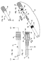
- FIG. 6 is an exploded front perspective view of the terminated coaxial connector of FIG. 4 .
- FIG. 7 is a cross-sectional view of the terminated coaxial connector of FIG. 4 taken along line 7 — 7 in FIG. 5 .
- FIG. 8 is a rear perspective view of a rear plug for use with the terminated coaxial connector of FIG. 4 .
- FIG. 9 is a front view of the rear plug of FIG. 8 .
- FIG. 10 is a cross-sectional view of the rear plug of FIG. 8, taken along line 10 — 10 in FIG. 9 .
- FIG. 11 is a front perspective view of an end cap for use with the terminated coaxial connector of FIG. 4 .
- FIG. 12 is a front end view of the end cap of FIG. 1 .
- FIG. 13 is a cross-sectional view of the end cap of FIG. 11 taken along line 13 — 13 in FIG. 12 .
- FIG. 14 is a front perspective view of a first alternative terminated coaxial connector in accordance with the present invention.
- FIG. 15 is an exploded front perspective view of the terminated coaxial connector of FIG. 14 .
- FIG. 16 is a side view of the terminated coaxial connector of FIG. 14 .
- FIG. 17 is a cross-sectional view of the terminated coaxial connector of FIG. 14, taken along line 17 — 17 of FIG. 16 .
- FIG. 18 is a front perspective view of a second alternative terminated coaxial connector is accordance with the present invention.
- FIG. 19 is a rear perspective view of the terminated coaxial connector of FIG. 18 .
- FIG. 20 is an exploded front perspective view of the terminate coaxial connector of FIG. 18 .
- FIG. 21 is a side view of the terminated coaxial connector of FIG. 18 .
- FIG. 22 is a cross-sectional view of the terminated coaxial connector of FIG. 18 taken along line 22 — 22 in FIG. 21 .
- the desired level of impedance across the connector is 75 Ohms.
- other levels of impedance may be preferred.
- a prior art terminated coaxial plug connector 110 is shown in FIGS. 1 through 3 and includes a mating opening 112 for mating with a coaxial jack.
- a rotating locking mechanism 118 engages the coaxial jack to prevent inadvertent or accidental removal.
- Within a cylindrical conductive outer shell 114 is mounted an insulator 122 which electrical isolates a center conductor 116 substantially in the center of mating opening 112 .
- a first lead or end 126 of a resistor 124 is mounted to center conductor 116 opposite mating opening 112 and electrically connects conductive outer shell 114 and center conductor 116 at a second lead or end 128 .
- a rear cap 120 encloses the rear of terminated coaxial connector 110 .
- connector 110 is attached to a coaxial connector jack.
- Outer shell 114 contacts a ring conductor of the jack and center conductor 116 contacts a tip conductor of the jack.
- Resistor 124 electrically connects outer shell 114 and center conductor 116 to provide a return signal on the circuit connected to the jack. The level of impedance of this return signal is governed by resistor 124 .
- resistor 124 may be inserted substantially axially aligned within outer shell 114 , when second end 128 is connected to outer shell 114 , resistor 124 becomes displaced from this axial alignment, often to such an extent that resistor 124 comes into contact with outer shell 114 , as shown in FIG. 3 .
- the connection between second end 128 and outer shell 114 is typically a physical and electrical connection such as a solder connection. Second end 128 may extend outside of outer shell 114 through a notch 132 and be received within a relief 130 in outer shell 114 . In such a connection, rear cap 120 would serve to provide additional security to the physical and electrical connection between second end 128 and outer shell 114 .
- FIGS. 4 through 7 show a terminated coaxial connector 10 in accordance with the present invention.
- Connector 10 including an axially aligned resistor 24 .
- Connector 10 is a BNC style connector and defines a mating opening 12 .
- Connector 10 further includes a cylindrical conductive outer housing 14 , a center conductor 16 within mating opening 12 and a locking mechanism 18 about outer housing 14 .
- An insulator 22 is mounted within outer housing 14 and provides a center axial channel 32 into which a center conductor 16 is mounted with a first end 36 extending into mating opening 12 . Insulator 22 holds center conductor 16 axially aligned within outer housing 14 and electrically isolates center conductor 16 from outer shell 14 .
- a first end 26 of resistor 24 is crimped onto a second end 34 of center conductor 16 .
- a second end 28 of resistor 24 is inserted through and crimped to a rear plug 30 .
- Rear plug 30 is mounted to an end of outer housing 14 opposite mating end 12 and is electrically conductive to provide an electrical path between resistor 24 and outer housing 14 .
- a rear cap 20 in mounted over rear plug 30 .
- the crimped connection between second end 28 and rear plug 30 , and the physical connection between outer housing 14 and rear plug 30 when rear plug 30 is mounted as shown in FIGS. 4 to 7 provide a consistent electrical connection between resistor 24 and outer housing 14 .
- the crimping and physical connections do not require heating or soldering.
- Rear plug 30 supports resistor 24 so that resistor 24 remains in a consistent axially aligned position within outer housing 14 .
- the quality of the connections and the consistent location of resistor 24 within connector 10 allow connector 10 to provide a predictable level of impedance when connector 10 is used to terminate an open circuit through a coaxial connector jack.
- washers 38 and 42 and a wave washer 40 which cooperate to aid in the rotation and lateral movement of locking mechanism 18 about outer housing 14 .
- Rear plug 30 is made of an electrically conductive material and includes a central axial opening 44 through which is received second end 28 of resistor 24 .
- a bevel 48 aids in the insertion of second end 28 into opening 44 .
- Opposite bevel 48 is a crimp extension 46 which is compressed about second end 28 to crimp rear plug 30 to resistor 24 .
- Rear plug 30 also includes a first wall 50 which is inserted within outer housing 14 . First wall 50 may be knurled as shown to aid in insertion and improve the physical and electrical connection between rear plug 30 and outer housing 14 .
- a lip 54 engages an end of outer housing 14 opposite mating end 12 and serves as a depth limiter for the insertion of rear plug 30 within outer housing 14 .
- a second wall 52 has a greater diameter than first wall 50 .
- Second wall 52 has a diameter approximately the same as a rear portion 68 of outer housing 14 and engages an interior wall 64 of rear cap 20 , discussed in further detail below.
- Second wall 52 may also be knurled as shown to aid the insertion of rear cap 20 about rear plug 30 and rear portion 68 and improve the physical connection of rear cap 20 and rear plug 30 .
- FIGS. 11 through 13 show rear cap 20 including a cylindrical interior space 56 closed at one end by an end wall 66 .
- Cylindrical interior 56 includes a first portion 58 enclosed by a wall 62 and a second portion 60 enclosed by wall 64 .
- First portion 58 has a larger diameter than rear portion 68 and second wall 52 .
- inner wall 64 which has a marginally smaller diameter than second wall 52 , engages rear plug 30 and is held to connector 10 . It is contemplated that other combinations of inner diameters within rear cap 20 and outer diameters of outer housing 14 and rear plug 30 may be used to secure rear cap 20 about rear portion 68 of connector 10 .
- FIGS. 14 through 17 a first alternative embodiment terminated coaxial connector 210 is shown, for use with WECO mid-size telecommunications jacks.
- the structure of connector 210 is substantially similar to that of connector 10 , with several components having slightly different shapes to mate with the tip and ring contacts of the mid-size jack.
- a pair of insulator halves 222 centrally mount a center conductor 216 within an outer housing 214 so that a first end 236 is within a mating end 212 .
- First end 26 of resistor 24 is crimped to a second end 234 of center conductor 216 and second end 28 is crimped within an opening 244 of a rear plug 230 .
- Rear plug 230 is mounted within a rear portion 268 of outer housing 214 and a rear cap 220 is mounted about rear portion 268 so that a first interior wall 264 of rear cap 220 engages a second wall 252 of rear plug 230 and a second interior wall 262 of rear 230 engages a raised area 270 to secure rear cap 220 to connector 210 .
- FIGS. 18 through 22 a second alternative embodiment terminated coaxial connector 310 is shown, for use with F-connector telecommunications jacks.
- the structure of connector 310 is substantially similar to that of connector 10 , with several components having slightly different shapes to mate with the tip and ring contacts of the F-connector jack.
- a pair of insulator halves 322 centrally mount a center conductor 316 within an outer housing 314 so that a first end 336 is within a mating end 312 .
- First end 26 of resistor 24 is crimped to a second end 334 of center conductor 316 and second end 28 is crimped at a crimp sleeve 346 within an opening 344 of a rear plug 330 .
- Rear plug 330 is mounted within a rear portion 368 of outer housing 314 so that first wall 350 engages an interior wall 351 of outer housing 314 .
- No rear cap is shown mounted to connector 314 although a rear cap could be adapted to fit about rear portion 368 similar to the previously disclosed embodiments.
- terminated coaxial connectors in accordance with the present invention may be adapted for other standard or proprietary coaxial connector jacks.
- These other jacks include but are not limited to TNC, RCA, WECO standard size, MUSA mini and standard size, 7-16 DIN, N-format, 1.6/5.6 and LCJ jacks.
- the adaptations required to construct terminated coaxial connectors in accordance with the present invention will be similar to the adaptations made for the two alternative embodiments described above, wherein the mating end portion of the connector will be adapted to fit the jack, while the rear portion of the plug will include the outer housing or ring conductor, the resistor crimped to the center or tip conductor and a rear plug holding the resistor fixed axially within the housing.
- a method of assembly of connector 10 may include inserting and press-fitting insulator 22 within outer housing 14 , where friction will hold insulator 22 in place.
- First end 26 of resistor 24 is trimmed to a desired length, for example, in the illustrated embodiment of connector 10 , first end 26 preferably extends approximately 0.20 inches from resistor 24 .
- First end 26 is inserted within an opening in second end 34 of center conductor 16 .
- Second end 34 of center conductor 16 is crimped about first end 26 , securing and electrically connecting resistor 24 and center conductor 16 .
- Second end 28 of resistor 24 is then placed within opening 44 of rear plug 30 .
- center conductor 16 , resistor 24 and rear plug 30 are then connected with outer housing 14 by inserting and press-fitting center conductor 16 within axial opening 32 of insulator 22 and inserting and press-fitting rear plug 30 into rear portion 68 of outer housing 14 .
- resistor 24 is axially aligned within outer housing 14 and electrically connected to outer housing 14 by electrically conductive rear plug 30 . Tension is then applied to second end 28 of resistor 24 to ensure that resistor 24 is not canted within outer housing 14 .
- Crimp sleeve 46 of rear plug 30 is then compressed and crimped about second end 28 of resistor 24 . Second end 28 is then trimmed substantially flush with crimp sleeve 46 . So crimped at both ends, resistor 24 is now held axially aligned within outer housing 14 so that a consistent level of impedance can be provided by connector 10 .
- Rear cap 20 is placed over rear portion 68 of connector 10 and secured in place. Rear cap 20 provides additional protection to the internal components of connector 10 .
- Alternative assembly approaches are anticipated and suggested by the foregoing description within the scope of the present invention.
Landscapes
- Coupling Device And Connection With Printed Circuit (AREA)
- Details Of Connecting Devices For Male And Female Coupling (AREA)
Priority Applications (10)
| Application Number | Priority Date | Filing Date | Title |
|---|---|---|---|
| US10/264,998 US6712647B2 (en) | 2002-07-22 | 2002-10-03 | Terminated coaxial connector |
| CA002492851A CA2492851A1 (en) | 2002-07-22 | 2003-05-07 | Terminated coaxial connector |
| EP03765430A EP1525645A1 (de) | 2002-07-22 | 2003-05-07 | Abgeschlossener koaxialverbinder |
| HK05111706.7A HK1080617B (en) | 2002-07-22 | 2003-05-07 | Terminated coaxial connector and a method of assembling the same |
| MXPA05000855A MXPA05000855A (es) | 2002-07-22 | 2003-05-07 | Conector coaxial terminal. |
| CNB038176823A CN100352110C (zh) | 2002-07-22 | 2003-05-07 | 端接同轴连接器及其装配方法 |
| AU2003232141A AU2003232141B2 (en) | 2002-07-22 | 2003-05-07 | Terminated coaxial connector |
| KR1020057001091A KR100991974B1 (ko) | 2002-07-22 | 2003-05-07 | 종단된 동축 커넥터 |
| PCT/US2003/015327 WO2004010543A1 (en) | 2002-07-22 | 2003-05-07 | Terminated coaxial connector |
| JP2005505501A JP4327161B2 (ja) | 2002-07-22 | 2003-05-07 | 終端同軸コネクタ |
Applications Claiming Priority (2)
| Application Number | Priority Date | Filing Date | Title |
|---|---|---|---|
| US20162102A | 2002-07-22 | 2002-07-22 | |
| US10/264,998 US6712647B2 (en) | 2002-07-22 | 2002-10-03 | Terminated coaxial connector |
Related Parent Applications (1)
| Application Number | Title | Priority Date | Filing Date |
|---|---|---|---|
| US20162102A Continuation-In-Part | 2002-07-22 | 2002-07-22 |
Publications (2)
| Publication Number | Publication Date |
|---|---|
| US20040014363A1 US20040014363A1 (en) | 2004-01-22 |
| US6712647B2 true US6712647B2 (en) | 2004-03-30 |
Family
ID=30772542
Family Applications (1)
| Application Number | Title | Priority Date | Filing Date |
|---|---|---|---|
| US10/264,998 Expired - Lifetime US6712647B2 (en) | 2002-07-22 | 2002-10-03 | Terminated coaxial connector |
Country Status (9)
| Country | Link |
|---|---|
| US (1) | US6712647B2 (de) |
| EP (1) | EP1525645A1 (de) |
| JP (1) | JP4327161B2 (de) |
| KR (1) | KR100991974B1 (de) |
| CN (1) | CN100352110C (de) |
| AU (1) | AU2003232141B2 (de) |
| CA (1) | CA2492851A1 (de) |
| MX (1) | MXPA05000855A (de) |
| WO (1) | WO2004010543A1 (de) |
Cited By (7)
| Publication number | Priority date | Publication date | Assignee | Title |
|---|---|---|---|---|
| US20050026504A1 (en) * | 2003-07-31 | 2005-02-03 | Hiroaki Nishimura | Termination device |
| US20050176293A1 (en) * | 2002-01-18 | 2005-08-11 | Adc Telecommunications, Inc. | Triaxial connector and method |
| US20060286852A1 (en) * | 2005-06-21 | 2006-12-21 | Hon Hai Precision Ind. Co., Ltd. | Power connector with ID identifying member |
| US20070251086A1 (en) * | 2006-04-28 | 2007-11-01 | Sullivan Robert W | Tool for insertion or removal of electrical connectors |
| US7435112B1 (en) * | 2008-02-08 | 2008-10-14 | Tyco Electronics Corporation | Electrical connector having a mechanical mating cycle limitation |
| US20180069355A1 (en) * | 2016-09-05 | 2018-03-08 | Hirose Electric Co., Ltd. | Termination device |
| US11158981B2 (en) * | 2019-06-14 | 2021-10-26 | Ezconn Corporation | Coaxial cable connector |
Families Citing this family (14)
| Publication number | Priority date | Publication date | Assignee | Title |
|---|---|---|---|---|
| JP4377736B2 (ja) * | 2004-04-07 | 2009-12-02 | 株式会社オートネットワーク技術研究所 | シールド電線用コネクタおよびそのシールド電線との接続方法 |
| DE102005048248B4 (de) | 2005-10-07 | 2015-12-03 | Amphenol-Tuchel Electronics Gmbh | Abschlussstecker für Antennenanlagen und Steckverbindung mit einem solchen Abschlussstecker |
| US7479033B1 (en) * | 2007-07-23 | 2009-01-20 | Tyco Electronics Corporation | High performance coaxial connector |
| FR2937189A1 (fr) * | 2008-10-13 | 2010-04-16 | Radiall Sa | Element de connecteur coaxial a prehension facilitee. |
| KR100932439B1 (ko) * | 2009-09-14 | 2009-12-17 | 서문원 | Bnc커넥터의 캔 제조장치 및 방법 |
| US8579659B2 (en) * | 2012-03-13 | 2013-11-12 | Carlisle Interconnect Technologies, Inc. | SMP electrical connector and connector system |
| WO2014179718A1 (en) * | 2013-05-03 | 2014-11-06 | Ppc Broadband, Inc. | Interface terminating device |
| JP5915594B2 (ja) * | 2013-05-30 | 2016-05-11 | 住友電装株式会社 | 電子部品付きコネクタ |
| US10454871B2 (en) * | 2014-11-26 | 2019-10-22 | Google Llc | Systems and methods for generating a message topic training dataset from user interactions in message clients |
| CN105576438B (zh) * | 2015-09-30 | 2018-01-09 | 中航光电科技股份有限公司 | 一种连接器壳体及连接器 |
| FR3042320B1 (fr) * | 2015-10-09 | 2017-12-08 | Delta Composants | Composant electrique comportant des broches de couplage electrique, au moins une broche etant partiellement isolee par l'enveloppe d'une resistance electrique |
| US10938153B2 (en) * | 2018-11-06 | 2021-03-02 | Optim Microwave Inc. | Waveguide quick-connect mechanism, waveguide window/seal, and portable antenna |
| KR102713890B1 (ko) * | 2022-01-12 | 2024-10-07 | (주)에스알테크날러지 | 저항을 포함하는 터미네이션 |
| US12592506B2 (en) | 2023-04-12 | 2026-03-31 | Amphenol Cable And Interconnect Technologies, Inc. | Electrical connector assembly with snap locking features |
Citations (9)
| Publication number | Priority date | Publication date | Assignee | Title |
|---|---|---|---|---|
| US3302159A (en) * | 1964-08-11 | 1967-01-31 | Amp Inc | Pluggable electrical connectors |
| US4469386A (en) * | 1981-09-23 | 1984-09-04 | Viewsonics, Inc. | Tamper-resistant terminator for a female coaxial plug |
| US4660921A (en) | 1985-11-21 | 1987-04-28 | Lrc Electronics, Inc. | Self-terminating coaxial connector |
| US4838813A (en) * | 1988-05-10 | 1989-06-13 | Amp Incorporated | Terminator plug with electrical resistor |
| US5011422A (en) * | 1990-08-13 | 1991-04-30 | Yeh Ming Hwa | Coaxial cable output terminal safety plug device |
| US5046968A (en) * | 1989-09-28 | 1991-09-10 | Tri-Star Incorporated | Electrical connector contact having an electrical component disposed in a central internal cavity |
| US5730612A (en) | 1995-12-08 | 1998-03-24 | Nippon Antenna Company Ltd. | Coaxial connector with built-in terminal |
| US5921793A (en) | 1996-05-31 | 1999-07-13 | The Whitaker Corporation | Self-terminating coaxial connector |
| US6019622A (en) | 1997-03-03 | 2000-02-01 | Uro Denshi Kogyo Kabushiki Kaisha | Termination coaxial connector |
-
2002
- 2002-10-03 US US10/264,998 patent/US6712647B2/en not_active Expired - Lifetime
-
2003
- 2003-05-07 CA CA002492851A patent/CA2492851A1/en not_active Abandoned
- 2003-05-07 KR KR1020057001091A patent/KR100991974B1/ko not_active Expired - Fee Related
- 2003-05-07 AU AU2003232141A patent/AU2003232141B2/en not_active Ceased
- 2003-05-07 MX MXPA05000855A patent/MXPA05000855A/es active IP Right Grant
- 2003-05-07 CN CNB038176823A patent/CN100352110C/zh not_active Expired - Fee Related
- 2003-05-07 JP JP2005505501A patent/JP4327161B2/ja not_active Expired - Fee Related
- 2003-05-07 WO PCT/US2003/015327 patent/WO2004010543A1/en not_active Ceased
- 2003-05-07 EP EP03765430A patent/EP1525645A1/de not_active Withdrawn
Patent Citations (9)
| Publication number | Priority date | Publication date | Assignee | Title |
|---|---|---|---|---|
| US3302159A (en) * | 1964-08-11 | 1967-01-31 | Amp Inc | Pluggable electrical connectors |
| US4469386A (en) * | 1981-09-23 | 1984-09-04 | Viewsonics, Inc. | Tamper-resistant terminator for a female coaxial plug |
| US4660921A (en) | 1985-11-21 | 1987-04-28 | Lrc Electronics, Inc. | Self-terminating coaxial connector |
| US4838813A (en) * | 1988-05-10 | 1989-06-13 | Amp Incorporated | Terminator plug with electrical resistor |
| US5046968A (en) * | 1989-09-28 | 1991-09-10 | Tri-Star Incorporated | Electrical connector contact having an electrical component disposed in a central internal cavity |
| US5011422A (en) * | 1990-08-13 | 1991-04-30 | Yeh Ming Hwa | Coaxial cable output terminal safety plug device |
| US5730612A (en) | 1995-12-08 | 1998-03-24 | Nippon Antenna Company Ltd. | Coaxial connector with built-in terminal |
| US5921793A (en) | 1996-05-31 | 1999-07-13 | The Whitaker Corporation | Self-terminating coaxial connector |
| US6019622A (en) | 1997-03-03 | 2000-02-01 | Uro Denshi Kogyo Kabushiki Kaisha | Termination coaxial connector |
Cited By (14)
| Publication number | Priority date | Publication date | Assignee | Title |
|---|---|---|---|---|
| US7281948B2 (en) | 2002-01-18 | 2007-10-16 | Adc Telecommunications, Inc. | Triaxial connector and method |
| US20050176293A1 (en) * | 2002-01-18 | 2005-08-11 | Adc Telecommunications, Inc. | Triaxial connector and method |
| US7140912B2 (en) * | 2002-01-18 | 2006-11-28 | Adc Telecommunications, Inc. | Triaxial connector and method |
| US20070037446A1 (en) * | 2002-01-18 | 2007-02-15 | Adc Telecommunications, Inc. | Triaxial connector and method |
| US6942522B2 (en) * | 2003-07-31 | 2005-09-13 | Hirose Electric Co., Ltd. | Termination device |
| US20050026504A1 (en) * | 2003-07-31 | 2005-02-03 | Hiroaki Nishimura | Termination device |
| US20060286852A1 (en) * | 2005-06-21 | 2006-12-21 | Hon Hai Precision Ind. Co., Ltd. | Power connector with ID identifying member |
| US7318744B2 (en) * | 2005-06-21 | 2008-01-15 | Hon Hai Precision Ind. Co., Ltd. | Power connector with ID identifying member |
| US7788788B2 (en) * | 2006-04-28 | 2010-09-07 | Robert W Sullivan | Tool for insertion or removal of electrical connectors |
| US20070251086A1 (en) * | 2006-04-28 | 2007-11-01 | Sullivan Robert W | Tool for insertion or removal of electrical connectors |
| US7435112B1 (en) * | 2008-02-08 | 2008-10-14 | Tyco Electronics Corporation | Electrical connector having a mechanical mating cycle limitation |
| US10003162B2 (en) * | 2016-09-05 | 2018-06-19 | Hirose Electric Co., Ltd. | Termination device |
| US20180069355A1 (en) * | 2016-09-05 | 2018-03-08 | Hirose Electric Co., Ltd. | Termination device |
| US11158981B2 (en) * | 2019-06-14 | 2021-10-26 | Ezconn Corporation | Coaxial cable connector |
Also Published As
| Publication number | Publication date |
|---|---|
| US20040014363A1 (en) | 2004-01-22 |
| CN100352110C (zh) | 2007-11-28 |
| KR20060006758A (ko) | 2006-01-19 |
| CA2492851A1 (en) | 2004-01-29 |
| AU2003232141B2 (en) | 2008-01-31 |
| CN1672300A (zh) | 2005-09-21 |
| AU2003232141A1 (en) | 2004-02-09 |
| MXPA05000855A (es) | 2005-04-19 |
| HK1080617A1 (en) | 2006-04-28 |
| JP4327161B2 (ja) | 2009-09-09 |
| WO2004010543A1 (en) | 2004-01-29 |
| JP2005534160A (ja) | 2005-11-10 |
| EP1525645A1 (de) | 2005-04-27 |
| KR100991974B1 (ko) | 2010-11-04 |
Similar Documents
| Publication | Publication Date | Title |
|---|---|---|
| US6712647B2 (en) | Terminated coaxial connector | |
| US4412717A (en) | Coaxial connector plug | |
| US4453796A (en) | Coaxial connector plug | |
| JP2005534160A5 (de) | ||
| US6146196A (en) | Mated coaxial contact system | |
| US20050001697A1 (en) | Electronic filter assembly | |
| EP0105723A1 (de) | Verbinder für ein abgeschirmtes Kabel | |
| US5261839A (en) | Angled electrical connector | |
| US9780430B2 (en) | Terminal connection comprising an HF conductor, in particular for a coaxial cable, and method for producing said terminal connection | |
| US4659164A (en) | Diode connector | |
| US4648681A (en) | Filtered electrical plug | |
| US6309250B1 (en) | Coaxial connector termination | |
| US20030224658A1 (en) | Electrical connector | |
| WO1996031925A1 (en) | Right angled coaxial connector | |
| US20050250381A1 (en) | Connector for a coaxial cable | |
| AU2000276087B2 (en) | Self-terminating electrical connector | |
| CA2361452A1 (en) | Hf coaxial angled plug connector part | |
| JP2683707B2 (ja) | 同軸ケーブルコネクタ | |
| JP2005050752A (ja) | 同軸ケーブル用中継アダプタ | |
| JPS5915409Y2 (ja) | コネクタ−用ピン接触子 | |
| JP2003109712A (ja) | 同軸コネクタ | |
| CA2098208C (en) | Angled electrical connector | |
| JPH025501Y2 (de) | ||
| CA1141444A (en) | Electrical filter assembly | |
| JPH11307189A (ja) | 同軸コネクタ |
Legal Events
| Date | Code | Title | Description |
|---|---|---|---|
| AS | Assignment |
Owner name: ADC TELECOMMUNICATIONS, INC., MINNESOTA Free format text: ASSIGNMENT OF ASSIGNORS INTEREST;ASSIGNORS:KHEMAKHEM, M'HAMED ANIS;PETERS, JEFF;SCHMIDT, JOHN DAVID;REEL/FRAME:013613/0618;SIGNING DATES FROM 20021024 TO 20021029 |
|
| STCF | Information on status: patent grant |
Free format text: PATENTED CASE |
|
| CC | Certificate of correction | ||
| FPAY | Fee payment |
Year of fee payment: 4 |
|
| FPAY | Fee payment |
Year of fee payment: 8 |
|
| AS | Assignment |
Owner name: TYCO ELECTRONICS SERVICES GMBH, SWITZERLAND Free format text: ASSIGNMENT OF ASSIGNORS INTEREST;ASSIGNOR:ADC TELECOMMUNICATIONS, INC.;REEL/FRAME:036060/0174 Effective date: 20110930 |
|
| FPAY | Fee payment |
Year of fee payment: 12 |
|
| AS | Assignment |
Owner name: COMMSCOPE EMEA LIMITED, IRELAND Free format text: ASSIGNMENT OF ASSIGNORS INTEREST;ASSIGNOR:TYCO ELECTRONICS SERVICES GMBH;REEL/FRAME:036956/0001 Effective date: 20150828 |
|
| AS | Assignment |
Owner name: COMMSCOPE TECHNOLOGIES LLC, NORTH CAROLINA Free format text: ASSIGNMENT OF ASSIGNORS INTEREST;ASSIGNOR:COMMSCOPE EMEA LIMITED;REEL/FRAME:037012/0001 Effective date: 20150828 |
|
| AS | Assignment |
Owner name: JPMORGAN CHASE BANK, N.A., AS COLLATERAL AGENT, ILLINOIS Free format text: PATENT SECURITY AGREEMENT (TERM);ASSIGNOR:COMMSCOPE TECHNOLOGIES LLC;REEL/FRAME:037513/0709 Effective date: 20151220 Owner name: JPMORGAN CHASE BANK, N.A., AS COLLATERAL AGENT, ILLINOIS Free format text: PATENT SECURITY AGREEMENT (ABL);ASSIGNOR:COMMSCOPE TECHNOLOGIES LLC;REEL/FRAME:037514/0196 Effective date: 20151220 Owner name: JPMORGAN CHASE BANK, N.A., AS COLLATERAL AGENT, IL Free format text: PATENT SECURITY AGREEMENT (ABL);ASSIGNOR:COMMSCOPE TECHNOLOGIES LLC;REEL/FRAME:037514/0196 Effective date: 20151220 Owner name: JPMORGAN CHASE BANK, N.A., AS COLLATERAL AGENT, IL Free format text: PATENT SECURITY AGREEMENT (TERM);ASSIGNOR:COMMSCOPE TECHNOLOGIES LLC;REEL/FRAME:037513/0709 Effective date: 20151220 |
|
| AS | Assignment |
Owner name: COMMSCOPE, INC. OF NORTH CAROLINA, NORTH CAROLINA Free format text: RELEASE BY SECURED PARTY;ASSIGNOR:JPMORGAN CHASE BANK, N.A.;REEL/FRAME:048840/0001 Effective date: 20190404 Owner name: ALLEN TELECOM LLC, ILLINOIS Free format text: RELEASE BY SECURED PARTY;ASSIGNOR:JPMORGAN CHASE BANK, N.A.;REEL/FRAME:048840/0001 Effective date: 20190404 Owner name: ANDREW LLC, NORTH CAROLINA Free format text: RELEASE BY SECURED PARTY;ASSIGNOR:JPMORGAN CHASE BANK, N.A.;REEL/FRAME:048840/0001 Effective date: 20190404 Owner name: COMMSCOPE TECHNOLOGIES LLC, NORTH CAROLINA Free format text: RELEASE BY SECURED PARTY;ASSIGNOR:JPMORGAN CHASE BANK, N.A.;REEL/FRAME:048840/0001 Effective date: 20190404 Owner name: REDWOOD SYSTEMS, INC., NORTH CAROLINA Free format text: RELEASE BY SECURED PARTY;ASSIGNOR:JPMORGAN CHASE BANK, N.A.;REEL/FRAME:048840/0001 Effective date: 20190404 Owner name: ALLEN TELECOM LLC, ILLINOIS Free format text: RELEASE BY SECURED PARTY;ASSIGNOR:JPMORGAN CHASE BANK, N.A.;REEL/FRAME:049260/0001 Effective date: 20190404 Owner name: ANDREW LLC, NORTH CAROLINA Free format text: RELEASE BY SECURED PARTY;ASSIGNOR:JPMORGAN CHASE BANK, N.A.;REEL/FRAME:049260/0001 Effective date: 20190404 Owner name: REDWOOD SYSTEMS, INC., NORTH CAROLINA Free format text: RELEASE BY SECURED PARTY;ASSIGNOR:JPMORGAN CHASE BANK, N.A.;REEL/FRAME:049260/0001 Effective date: 20190404 Owner name: COMMSCOPE, INC. OF NORTH CAROLINA, NORTH CAROLINA Free format text: RELEASE BY SECURED PARTY;ASSIGNOR:JPMORGAN CHASE BANK, N.A.;REEL/FRAME:049260/0001 Effective date: 20190404 Owner name: COMMSCOPE TECHNOLOGIES LLC, NORTH CAROLINA Free format text: RELEASE BY SECURED PARTY;ASSIGNOR:JPMORGAN CHASE BANK, N.A.;REEL/FRAME:049260/0001 Effective date: 20190404 |
|
| AS | Assignment |
Owner name: JPMORGAN CHASE BANK, N.A., NEW YORK Free format text: TERM LOAN SECURITY AGREEMENT;ASSIGNORS:COMMSCOPE, INC. OF NORTH CAROLINA;COMMSCOPE TECHNOLOGIES LLC;ARRIS ENTERPRISES LLC;AND OTHERS;REEL/FRAME:049905/0504 Effective date: 20190404 Owner name: WILMINGTON TRUST, NATIONAL ASSOCIATION, AS COLLATE Free format text: PATENT SECURITY AGREEMENT;ASSIGNOR:COMMSCOPE TECHNOLOGIES LLC;REEL/FRAME:049892/0051 Effective date: 20190404 Owner name: JPMORGAN CHASE BANK, N.A., NEW YORK Free format text: ABL SECURITY AGREEMENT;ASSIGNORS:COMMSCOPE, INC. OF NORTH CAROLINA;COMMSCOPE TECHNOLOGIES LLC;ARRIS ENTERPRISES LLC;AND OTHERS;REEL/FRAME:049892/0396 Effective date: 20190404 Owner name: WILMINGTON TRUST, NATIONAL ASSOCIATION, AS COLLATERAL AGENT, CONNECTICUT Free format text: PATENT SECURITY AGREEMENT;ASSIGNOR:COMMSCOPE TECHNOLOGIES LLC;REEL/FRAME:049892/0051 Effective date: 20190404 |
|
| AS | Assignment |
Owner name: WILMINGTON TRUST, DELAWARE Free format text: SECURITY INTEREST;ASSIGNORS:ARRIS SOLUTIONS, INC.;ARRIS ENTERPRISES LLC;COMMSCOPE TECHNOLOGIES LLC;AND OTHERS;REEL/FRAME:060752/0001 Effective date: 20211115 |
|
| AS | Assignment |
Owner name: RUCKUS WIRELESS, LLC (F/K/A RUCKUS WIRELESS, INC.), NORTH CAROLINA Free format text: RELEASE OF SECURITY INTEREST AT REEL/FRAME 049905/0504;ASSIGNOR:JPMORGAN CHASE BANK, N.A., AS COLLATERAL AGENT;REEL/FRAME:071477/0255 Effective date: 20241217 Owner name: COMMSCOPE TECHNOLOGIES LLC, NORTH CAROLINA Free format text: RELEASE OF SECURITY INTEREST AT REEL/FRAME 049905/0504;ASSIGNOR:JPMORGAN CHASE BANK, N.A., AS COLLATERAL AGENT;REEL/FRAME:071477/0255 Effective date: 20241217 Owner name: COMMSCOPE, INC. OF NORTH CAROLINA, NORTH CAROLINA Free format text: RELEASE OF SECURITY INTEREST AT REEL/FRAME 049905/0504;ASSIGNOR:JPMORGAN CHASE BANK, N.A., AS COLLATERAL AGENT;REEL/FRAME:071477/0255 Effective date: 20241217 Owner name: ARRIS SOLUTIONS, INC., NORTH CAROLINA Free format text: RELEASE OF SECURITY INTEREST AT REEL/FRAME 049905/0504;ASSIGNOR:JPMORGAN CHASE BANK, N.A., AS COLLATERAL AGENT;REEL/FRAME:071477/0255 Effective date: 20241217 Owner name: ARRIS TECHNOLOGY, INC., NORTH CAROLINA Free format text: RELEASE OF SECURITY INTEREST AT REEL/FRAME 049905/0504;ASSIGNOR:JPMORGAN CHASE BANK, N.A., AS COLLATERAL AGENT;REEL/FRAME:071477/0255 Effective date: 20241217 Owner name: ARRIS ENTERPRISES LLC (F/K/A ARRIS ENTERPRISES, INC.), NORTH CAROLINA Free format text: RELEASE OF SECURITY INTEREST AT REEL/FRAME 049905/0504;ASSIGNOR:JPMORGAN CHASE BANK, N.A., AS COLLATERAL AGENT;REEL/FRAME:071477/0255 Effective date: 20241217 |