US6705155B2 - Apparatus and method for monitoring tire condition - Google Patents
Apparatus and method for monitoring tire condition Download PDFInfo
- Publication number
- US6705155B2 US6705155B2 US09/957,229 US95722901A US6705155B2 US 6705155 B2 US6705155 B2 US 6705155B2 US 95722901 A US95722901 A US 95722901A US 6705155 B2 US6705155 B2 US 6705155B2
- Authority
- US
- United States
- Prior art keywords
- signal
- tire
- tires
- transmitter device
- reception antenna
- Prior art date
- Legal status (The legal status is an assumption and is not a legal conclusion. Google has not performed a legal analysis and makes no representation as to the accuracy of the status listed.)
- Expired - Fee Related
Links
Images


Classifications
-
- B—PERFORMING OPERATIONS; TRANSPORTING
- B60—VEHICLES IN GENERAL
- B60C—VEHICLE TYRES; TYRE INFLATION; TYRE CHANGING; CONNECTING VALVES TO INFLATABLE ELASTIC BODIES IN GENERAL; DEVICES OR ARRANGEMENTS RELATED TO TYRES
- B60C23/00—Devices for measuring, signalling, controlling, or distributing tyre pressure or temperature, specially adapted for mounting on vehicles; Arrangement of tyre inflating devices on vehicles, e.g. of pumps or of tanks; Tyre cooling arrangements
- B60C23/02—Signalling devices actuated by tyre pressure
- B60C23/04—Signalling devices actuated by tyre pressure mounted on the wheel or tyre
- B60C23/0408—Signalling devices actuated by tyre pressure mounted on the wheel or tyre transmitting the signals by non-mechanical means from the wheel or tyre to a vehicle body mounted receiver
- B60C23/0415—Automatically identifying wheel mounted units, e.g. after replacement or exchange of wheels
- B60C23/0416—Automatically identifying wheel mounted units, e.g. after replacement or exchange of wheels allocating a corresponding wheel position on vehicle, e.g. front/left or rear/right
-
- B—PERFORMING OPERATIONS; TRANSPORTING
- B60—VEHICLES IN GENERAL
- B60C—VEHICLE TYRES; TYRE INFLATION; TYRE CHANGING; CONNECTING VALVES TO INFLATABLE ELASTIC BODIES IN GENERAL; DEVICES OR ARRANGEMENTS RELATED TO TYRES
- B60C23/00—Devices for measuring, signalling, controlling, or distributing tyre pressure or temperature, specially adapted for mounting on vehicles; Arrangement of tyre inflating devices on vehicles, e.g. of pumps or of tanks; Tyre cooling arrangements
- B60C23/02—Signalling devices actuated by tyre pressure
- B60C23/04—Signalling devices actuated by tyre pressure mounted on the wheel or tyre
- B60C23/0408—Signalling devices actuated by tyre pressure mounted on the wheel or tyre transmitting the signals by non-mechanical means from the wheel or tyre to a vehicle body mounted receiver
- B60C23/0422—Signalling devices actuated by tyre pressure mounted on the wheel or tyre transmitting the signals by non-mechanical means from the wheel or tyre to a vehicle body mounted receiver characterised by the type of signal transmission means
- B60C23/0433—Radio signals
- B60C23/0435—Vehicle body mounted circuits, e.g. transceiver or antenna fixed to central console, door, roof, mirror or fender
- B60C23/0444—Antenna structures, control or arrangements thereof, e.g. for directional antennas, diversity antenna, antenna multiplexing or antennas integrated in fenders
-
- B—PERFORMING OPERATIONS; TRANSPORTING
- B60—VEHICLES IN GENERAL
- B60C—VEHICLE TYRES; TYRE INFLATION; TYRE CHANGING; CONNECTING VALVES TO INFLATABLE ELASTIC BODIES IN GENERAL; DEVICES OR ARRANGEMENTS RELATED TO TYRES
- B60C23/00—Devices for measuring, signalling, controlling, or distributing tyre pressure or temperature, specially adapted for mounting on vehicles; Arrangement of tyre inflating devices on vehicles, e.g. of pumps or of tanks; Tyre cooling arrangements
- B60C23/02—Signalling devices actuated by tyre pressure
- B60C23/04—Signalling devices actuated by tyre pressure mounted on the wheel or tyre
- B60C23/0408—Signalling devices actuated by tyre pressure mounted on the wheel or tyre transmitting the signals by non-mechanical means from the wheel or tyre to a vehicle body mounted receiver
- B60C23/0422—Signalling devices actuated by tyre pressure mounted on the wheel or tyre transmitting the signals by non-mechanical means from the wheel or tyre to a vehicle body mounted receiver characterised by the type of signal transmission means
- B60C23/0433—Radio signals
- B60C23/0447—Wheel or tyre mounted circuits
- B60C23/0455—Transmission control of wireless signals
- B60C23/0459—Transmission control of wireless signals self triggered by motion sensor
-
- B—PERFORMING OPERATIONS; TRANSPORTING
- B60—VEHICLES IN GENERAL
- B60C—VEHICLE TYRES; TYRE INFLATION; TYRE CHANGING; CONNECTING VALVES TO INFLATABLE ELASTIC BODIES IN GENERAL; DEVICES OR ARRANGEMENTS RELATED TO TYRES
- B60C23/00—Devices for measuring, signalling, controlling, or distributing tyre pressure or temperature, specially adapted for mounting on vehicles; Arrangement of tyre inflating devices on vehicles, e.g. of pumps or of tanks; Tyre cooling arrangements
- B60C23/02—Signalling devices actuated by tyre pressure
- B60C23/04—Signalling devices actuated by tyre pressure mounted on the wheel or tyre
- B60C23/0408—Signalling devices actuated by tyre pressure mounted on the wheel or tyre transmitting the signals by non-mechanical means from the wheel or tyre to a vehicle body mounted receiver
- B60C23/0422—Signalling devices actuated by tyre pressure mounted on the wheel or tyre transmitting the signals by non-mechanical means from the wheel or tyre to a vehicle body mounted receiver characterised by the type of signal transmission means
- B60C23/0433—Radio signals
- B60C23/0447—Wheel or tyre mounted circuits
- B60C23/0455—Transmission control of wireless signals
- B60C23/0462—Structure of transmission protocol
-
- B—PERFORMING OPERATIONS; TRANSPORTING
- B60—VEHICLES IN GENERAL
- B60C—VEHICLE TYRES; TYRE INFLATION; TYRE CHANGING; CONNECTING VALVES TO INFLATABLE ELASTIC BODIES IN GENERAL; DEVICES OR ARRANGEMENTS RELATED TO TYRES
- B60C23/00—Devices for measuring, signalling, controlling, or distributing tyre pressure or temperature, specially adapted for mounting on vehicles; Arrangement of tyre inflating devices on vehicles, e.g. of pumps or of tanks; Tyre cooling arrangements
- B60C23/02—Signalling devices actuated by tyre pressure
- B60C23/04—Signalling devices actuated by tyre pressure mounted on the wheel or tyre
- B60C23/0408—Signalling devices actuated by tyre pressure mounted on the wheel or tyre transmitting the signals by non-mechanical means from the wheel or tyre to a vehicle body mounted receiver
- B60C23/0422—Signalling devices actuated by tyre pressure mounted on the wheel or tyre transmitting the signals by non-mechanical means from the wheel or tyre to a vehicle body mounted receiver characterised by the type of signal transmission means
- B60C23/0433—Radio signals
- B60C23/0447—Wheel or tyre mounted circuits
- B60C23/0455—Transmission control of wireless signals
- B60C23/0464—Transmission control of wireless signals to avoid signal interference
-
- B—PERFORMING OPERATIONS; TRANSPORTING
- B60—VEHICLES IN GENERAL
- B60C—VEHICLE TYRES; TYRE INFLATION; TYRE CHANGING; CONNECTING VALVES TO INFLATABLE ELASTIC BODIES IN GENERAL; DEVICES OR ARRANGEMENTS RELATED TO TYRES
- B60C23/00—Devices for measuring, signalling, controlling, or distributing tyre pressure or temperature, specially adapted for mounting on vehicles; Arrangement of tyre inflating devices on vehicles, e.g. of pumps or of tanks; Tyre cooling arrangements
- B60C23/02—Signalling devices actuated by tyre pressure
- B60C23/04—Signalling devices actuated by tyre pressure mounted on the wheel or tyre
- B60C23/0486—Signalling devices actuated by tyre pressure mounted on the wheel or tyre comprising additional sensors in the wheel or tyre mounted monitoring device, e.g. movement sensors, microphones or earth magnetic field sensors
- B60C23/0489—Signalling devices actuated by tyre pressure mounted on the wheel or tyre comprising additional sensors in the wheel or tyre mounted monitoring device, e.g. movement sensors, microphones or earth magnetic field sensors for detecting the actual angular position of the monitoring device while the wheel is turning
Definitions
- the present invention relates to apparatuses and methods for monitoring the condition of a tire in a vehicle, and, more particularly, to techniques for determining which of several transmitter devices located respectively in the tires has transmitted data.
- each tire is monitored in a passenger compartment of the vehicle using a wireless tire condition monitoring apparatus. More specifically, a transmitter device is attached to each tire. The transmitter device measures, for example, the pressure and temperature in the corresponding tire. The transmitter device wirelessly transmits data that represents the measurements, or the condition of the tire. A receiver is installed in the vehicle's body frame and receives data from the transmitter devices.
- Each transmitter device transmits data that represents the condition of the corresponding tire to the single receiver.
- the receiver receives data from one transmitter device, the receiver must determine which tire corresponds to the data.
- each transmitter device has a specific identification code (ID code).
- ID code The transmitter device transmits the ID code together with the data that represents the condition of the tire. The receiver thus determines which transmitter device has transmitted the data in accordance with the ID code.
- the receiver must pre-store the ID codes of the transmitter devices that are attached to the corresponding tires. Further, when performing an initial entry of the ID codes in the receiver, each ID code must be associated with the position of the tire corresponding to the transmitter device that matches the ID code. Thus, every time a tire is replaced or the position of the tire is changed with respect to the vehicle, the initial entry must be repeated. Since this initial entry is done manually, the operation is complicated and time-consuming.
- the invention provides a tire condition monitoring apparatus for monitoring the condition of a plurality of tires attached to a vehicle.
- the tires include left and right front tires and left and right rear tires.
- a transmitter device is attached to each tire.
- the transmitter device has a condition sensor that detects the condition of the corresponding tire and a signal generator that generates a specific pattern signal when the tire rotates.
- the pattern signal generated by the signal generator of the transmitter device attached to each left tire is different from the pattern signal generated by the signal generator of the transmitter device attached to each right tire when the vehicle moves in a given direction.
- Each transmitter device transmits a radio signal that includes data that represents the tire condition and data that represents the pattern signal.
- a front reception antenna is installed in a body of the vehicle at a position that is relatively near to the left and right front tires.
- the front reception antenna receives radio signals from the transmitter devices.
- a rear reception antenna is installed in the vehicle body at a position that is relatively near to the left and right rear tires.
- the rear reception antenna receives radio signals from the transmitter devices.
- a receiver receives reception signals from the front and rear reception antennas.
- the receiver includes a controller. When one of the transmitter devices has transmitted a radio signal, the controller determines which transmitter device has transmitted the radio signal in accordance with the level of reception signals from the reception antennas and the data that represents the pattern signal, which is included in the radio signal transmitted by the transmitter device.
- the present invention also provides a tire condition monitoring method for monitoring the condition of a plurality of tires attached to a vehicle.
- the tires include left and right front tires and left and right rear tires.
- the method includes detecting the condition of each tire; generating a specific pattern signal for each tire when the tires rotate, wherein the pattern signal generated for each left tire is different from the pattern signal generated for each right tire; transmitting a radio signal from one of the tires, the radio signal including data that represents the tire condition and data that represents the pattern signal; receiving the radio signal at a front location that is relatively near to the front tires; receiving the radio signal at a rear location that is relatively near to the rear tires; and determining which tire has transmitted the radio signal in accordance with the level of signals received at the front and rear locations and the data that represents the pattern signal, which is included in the transmitted radio signal.
- FIG. 1 is a view schematically showing the structure of a tire condition monitoring apparatus of an embodiment according to the present invention
- FIG. 2 is a block diagram showing a circuit of a transmitter device of the tire condition monitoring apparatus of FIG. 1;
- FIG. 3 is a block diagram showing a circuit of a receiver of the tire condition monitoring apparatus of FIG. 1;
- FIG. 4 ( a ) is a cross-sectional view showing a rotational direction sensor located in the transmitter device of FIG. 2;
- FIG. 4 ( b ) is a cross-sectional view taken along line 4 ( b )— 4 ( b ) of FIG. 4 ( a );
- FIG. 4 ( c ) is a cross-sectional view taken along line 4 ( c )— 4 ( c ) of FIG. 4 ( a );
- FIG. 5 ( a ) is a timing chart showing a first signaling pattern of the rotational direction sensor
- FIG. 5 ( b ) is a timing chart showing a second signaling pattern of the rotational direction sensor.
- FIGS. 6 ( a ) to 6 ( c ) are views schematically explaining operation of the rotational direction sensor when the corresponding tire is rotating.
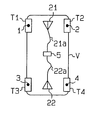
- a vehicle V includes a left, front tire T 1 , a right, front tire T 2 , a left, rear tire T 3 , and a right, rear tire T 4 .
- a tire condition monitoring apparatus has first to fourth transmitter devices 1 , 2 , 3 , 4 that are attached to the four tires T 1 , T 2 , T 3 , T 4 , respectively.
- the tire condition apparatus further includes a receiver 5 that is installed in a body frame of the vehicle V.
- Each transmitter device 1 - 4 is, for example, secured to the wheel of the corresponding tire T 1 -T 4 and is located in the tire T 1 -T 4 .
- Each transmitter device 1 - 4 monitors the condition of the corresponding tire T 1 -T 4 , or measures the pressure and temperature in the tire T 1 -T 4 . Each transmitter device 1 - 4 then wirelessly transmits data that represents the measurements. The receiver 5 receives the data from the transmitter devices 1 - 4 .
- the first to fourth transmitter devices 1 - 4 are identical. Thus, only the first transmitter device 1 will be described by way of example with reference to FIG. 2 .
- the transmitter device 1 includes a controller 10 , which is, for example, a microcomputer.
- the controller 10 includes, for example, a central processing unit (CPU), a random access memory (RAM), and a read only memory (ROM).
- the ROM pre-stores an ID code of the first transmitter device 1 .
- the ID code is used for distinguishing the first transmitter device 1 from the remaining transmitter devices 2 to 4 .
- a pressure sensor 11 measures the pressure in the corresponding tire, or the tire T 1 , and provides data that represents the measurement to the controller 10 .
- a temperature sensor 12 measures the temperature in the tire T 1 and provides data that represents the measurement to the controller 10 .
- the pressure sensor 11 and the temperature sensor 12 each function as a condition detecting means or a condition sensor.
- the controller 10 outputs data such as the data that represents the pressure measurement, the data that represents the temperature measurement, and data that includes the ID code stored in the ROM to a transmission circuit 14 .
- the transmission circuit 14 encodes and modulates the data from the controller 10 .
- the transmission circuit 14 then wirelessly transmits the data by a transmission antenna 15 .
- the transmitter device 1 includes a battery 16 .
- the battery 16 supplies power to the transmitter device 1 .
- the controller 10 instructs the pressure sensor 11 and the temperature sensor 12 to measure the pressure or temperature in the tire T 1 at predetermined time intervals (for example, every fifteen seconds). Further, every time the pressure sensor 11 completes a predetermined number of measurement cycles (for example, forty cycles), the controller 10 instructs the transmission circuit 14 to perform a periodic transmission. In addition, when determining that the pressure or temperature in the tire T 1 is abnormal, the controller 10 instructs the transmission circuit 14 to transmit data, regardless of the periodic transmission intervals.
- each transmitter device 1 - 4 performs the periodic transmission is out of phase with the timing at which the other transmitter devices 1 - 4 each perform the periodic transmission. That is, it is unlikely that two or more transmitter devices T 1 -T 4 perform the periodic transmission at the same time.
- a rotational direction sensor 13 which is a signal generating means or a signal generator, is connected to the controller 10 .
- the rotational direction sensor 13 includes a hollow, substantially donut-shaped case 30 .
- the case 30 includes a pair of case members 30 a , 30 b that are coupled with each other to form an annular space in the case 30 .
- An annular, base electrode plate 31 and an opposing annular, cut-away electrode plate 32 are received in the annular space in the case 30 .
- the base electrode plate 31 is secured to an inner wall of the case member 30 a .
- the cut-away electrode plate 32 is secured to an inner wall of the case member 30 b .
- an annular passage 33 that has a substantially V-shaped cross-sectional shape is formed between the electrode plates 31 , 32 .
- a ball 34 is formed of conductive material and is located in the annular passage 33 .
- the ball 34 rolls in the annular passage 33 to move circumferentially in the case 30 .
- the base electrode plate 31 includes a contact surface 31 a that contacts and supports the ball 34 .
- the cut-away electrode plate 32 includes a contact surface 32 a that contacts and supports the ball 34 .
- Each contact surface 31 a , 32 a forms a truncated conical surface.
- the ball 34 rolls along the contact surfaces 31 a , 32 b.
- the base electrode plate 31 is continuous in the circumferential direction and does not include any joints.
- the electrode plate 32 includes three cut-away portions 35 , or non-conductive portions, that extend in radial directions.
- the cut-away portions 35 divide the cut-away electrode plate 32 into a first section 321 , a second section 322 , and a third section 323 .
- the circumferential dimensions of the first to third sections 321 to 323 are different from one another. More specifically, the circumferential dimension of the first section 321 is larger than that of the second section 322 .
- the circumferential dimension of the second section 322 is larger than that of the third section 323 .
- the ball 34 When the ball 34 is located at a position in the annular passage 33 that corresponds to any one of the first to third sections 321 to 323 , the ball 34 contacts both electrode plates 31 , 32 , as shown in FIG. 4 ( a ). In this state, the electrode plates 31 , 32 are electrically connected to each other through the ball 34 . The rotational direction sensor 13 thus sends a high-level signal to the controller 10 . In contrast, when the ball 34 is located at a position in the annular passage 33 that corresponds to any one of the cut-away portions 35 , the ball 34 contacts the base electrode plate 31 but not the cut-away electrode plate 32 . In this state, the electrode plates 31 , 32 are electrically disconnected from each other. The rotational direction sensor 13 thus sends a low-level signal to the controller 10 .
- the rotational direction sensor 13 if the ball 34 moves clockwise in the annular passage 33 , as viewed in the drawing, at a constant speed, the rotational direction sensor 13 generates signals in accordance with the shape of the cut-away electrode plate 32 , as shown in FIG. 5 ( a ). More specifically, in this state, the rotational direction sensor 13 generates a first high-level signal H 1 , a second high-level signal H 2 , and a third high-level signal H 3 .
- the first high-level signal H 1 lasts for a time period that corresponds to the circumferential dimension of the first section 321 .
- the second high-level signal H 2 lasts for a time period that corresponds to the circumferential dimension of the second section 322 .
- the third high-level signal H 3 lasts for a time period that corresponds to the circumferential dimension of the third section 323 .
- the rotational direction sensor 13 When rolling clockwise in the annular passage 33 , as viewed in FIG. 4 ( c ), the ball 34 moves along the first section 321 , the third section 323 , and the second section 322 , in this order.
- the rotational direction sensor 13 generates the first high-level signal H 1 , the third high-level signal H 3 , and the second high-level signal H 2 , in this order.
- the signaling pattern shown in FIG. 5 ( a ) is defined as a first signaling pattern.
- the rotational direction sensor 13 generates the first high-level signal H 1 , the second high-level signal H 2 , and the third high-level signal H 3 , in this order.
- the signaling pattern shown in FIG. 5 ( b ) is defined as a second signaling pattern that is different from the first signaling pattern of FIG. 5 ( a ).
- Each transmitter device 1 - 4 is attached to the corresponding tire T 1 -T 4 such that the axis of the associated rotational direction sensor 13 , or the axis around which the ball 34 rolls, is parallel with the axis of the tire T 1 -T 4 .
- FIGS. 6 ( a ), 6 ( b ), and 6 ( c ) schematically show the left, front tire T 1 and the rotational direction sensor 13 that is located in the tire T 1 . If the tire T 1 rotates at a relatively low speed, gravity acts on the ball 34 to maintain the ball 34 at the lowermost position of the annular passage 33 constantly.
- the ball 34 is located at a position in the annular passage 33 that corresponds to the second section 322 . If the vehicle V proceeds forward and the tire T 1 rotates counterclockwise from the state of FIG. 6 ( a ) to the state of FIG. 6 ( b ), as viewed in the drawings, the ball 34 rolls clockwise relative to the annular passage 33 until it is located at a position that corresponds to the first section 321 . If the tire T 1 further rotates counterclockwise from the state of FIG. 6 ( b ) to the state of FIG. 6 ( c ), the ball 34 further rolls clockwise relative to the annular passage 33 until it is located at a position that corresponds to the third section 323 . Accordingly, when the vehicle V proceeds forward, the rotational direction sensor 13 in the tire T 1 generates signals in accordance with the first signaling pattern of FIG. 5 ( a ).
- the first, second, third, and fourth transmitter devices 1 - 4 which are attached to the four tires T 1 -T 4 , respectively, have identical mechanical structures.
- the rotational direction sensor 13 in the left, rear tire T 3 generates signals in accordance with the first signaling pattern, like the rotational direction sensor 13 in the left, front tire T 1 .
- the right, front and rear tires T 2 , T 4 are located at positions opposite to the left, front and rear tires T 1 , T 3 , respectively, with respect to a hypothetical vertical plane that includes the longitudinal axis of the vehicle V.
- the rotational direction sensors 13 in the left, front and rear tires T 1 , T 3 each generate signals in accordance with the second signaling pattern.
- the controller 10 of each transmitter device 1 - 4 starts analyzing the signaling pattern of the signals from the corresponding rotational direction sensor 13 . If at least one signaling cycle is completed by the rotational direction sensor 13 , the controller 10 judges whether the signaling pattern is the first signaling pattern or the second signaling pattern. The controller 10 then stores data that represents the judged signaling pattern in an internal memory, for example, the RAM.
- the controller 10 may judge the signaling pattern every time the rotational direction sensor 13 completes one signaling cycle. Alternatively, the controller 10 may judge the signaling pattern every time the rotational direction sensor 13 completes a plurality of signaling cycles. However, the tires T 1 -T 4 are not always rotating at a constant speed. Thus, for correct judgment, it is preferred that the controller 10 performs the judgment when the rotational direction sensor 13 completes a plurality of signaling patterns. After each judgment, the controller 10 rewrites the data stored in the internal memory such that only the latest data is stored in the memory.
- the controllers 10 may receive signals in accordance with a signaling pattern that is different from the signaling patterns of FIGS. 5 ( a ) and 5 ( b ). In this case, the controllers 10 do not determine the signaling pattern.
- the controller 10 discontinues the analysis of the signaling pattern. That is, if the vehicle V is stopped and the tires T 1 -T 4 are not rotating, the signaling pattern is not analyzed. Further, if each tire T 1 -T 4 rotates at a relatively high speed, centrifugal force acts to press the ball 34 to the electrode plates 31 , 32 of the corresponding rotational direction sensor 13 . The ball 34 is thus maintained at one position in the case 30 of the rotational direction sensor 13 . Thus, if the vehicle V travels at a relatively high speed, the signaling pattern is not analyzed. In other words, the signaling pattern is analyzed mainly when the vehicle V travels at a relatively low speed.
- the controller 10 of each rotational direction sensor 13 wirelessly transmits data that represents the signaling pattern stored in the internal memory, together with the data that represents the pressure and temperature in the corresponding tire T 1 -T 4 .
- the receiver 5 is powered by a battery (not shown) of the vehicle V, when, for example, a key switch (not shown) of the vehicle V is turned on.
- a front reception antenna 21 is located in a front portion of the vehicle V's body frame at a position that substantially corresponds to the left and right front tires T 1 , T 2 .
- a rear reception antenna 22 is located in a rear portion of the body frame at a position that substantially corresponds to the left and right rear tires T 3 , T 4 .
- the front reception antenna 21 is connected to the receiver 5 through a cable 21 a
- the rear reception antenna 22 is connected to the receiver 5 through a cable 22 a.
- the reception antennas 21 , 22 each receive the radio signal.
- Each reception antenna 21 , 22 induces voltage that corresponds to the field strength of the radio signal and sends a signal that represents the induced voltage to the receiver 5 .
- the level of the voltage induced by each reception antenna 21 , 22 varies in accordance with the position of the transmitter device 1 - 4 that has transmitted the radio signal relative to the reception antenna 21 , 22 .
- the level of the voltage induced by the front reception antenna 21 is larger than the level of the voltage induced by the rear reception antenna 22 .
- the level of the voltage induced by the front reception antenna 21 is smaller than the level of the voltage induced by the rear reception antenna 22 .
- the receiver 5 includes a controller 20 , which is, for example, a microcomputer.
- the controller 20 which functions as a control means, includes, for example, a CPU, an RAM, and an ROM.
- the receiver 5 also includes a switch circuit 23 and a reception circuit 24 .
- the switch circuit 23 is connected to the reception antennas 21 , 22 through the associated cables 21 a , 22 a .
- the reception circuit 24 is connected to the switch circuit 23 .
- the controller 20 controls the switch circuit 23 to selectively connect the front reception antenna 21 or the rear reception antenna 22 to the reception circuit 24 .
- the switch circuit 23 sends a voltage signal to the reception circuit 24 .
- the reception circuit 24 decodes and demodulates the voltage signal and sends the signal to the controller 20 .
- the controller 20 derives necessary data such as the data that represents the tire condition from the signal transmitted by the reception circuit 24 .
- the controller 20 stores the acquired information in an internal memory, for example, the RAM, and indicates the information on an indicator 25 that is located in the vehicle V's passenger compartment, as needed.
- An operation key 26 is also located in the passenger compartment. The operation key 26 is manually operable to select various functions of the tire condition monitoring apparatus.
- the controller 20 receives a signal that represents the direction in which the vehicle V is moving (a movement direction signal) from a directional indicator device of the vehicle V, for example, a device connected to the vehicle's transmission (not shown).
- the directional indicator device provides the controller 20 with a signal that represents the shift position of a shift lever as the movement direction signal.
- the controller 20 judges whether the vehicle V is moving forward or rearward in accordance with the movement direction signal. That is, the controller 20 determines that the vehicle V is moving rearward only when the shift lever is located at the reverse position. The controller 20 otherwise determines that the vehicle V is moving forward.
- the controller 20 controls the switch circuit 23 to connect one of the antennas 21 , 22 to the reception circuit 24 .
- the controller 20 connects the front reception antenna 21 to the reception circuit 24 when neither the front or rear reception antenna 21 , 22 is receiving a radio signal from any transmitter device 1 - 4 .
- the front and rear reception antennas 21 , 22 both receive the radio signal. Each reception antenna 21 , 22 then induces a voltage signal that corresponds to the field strength of the radio signal. Since the front reception antenna 21 is connected to the reception circuit 24 by default, as described, a signal from the front reception antenna 21 is sent to the controller 20 . The controller 20 then initiates a procedure for determining which transmitter device has transmitted the radio signal.
- the controller 20 first determines the level of the voltage signal from the front reception antenna 21 .
- the controller 20 then controls the switch circuit 23 to connect the rear reception antenna 22 to the reception circuit 24 . In this state, the controller 20 determines the level of the voltage signal from the rear reception antenna 22 .
- the controller 20 compares the levels of the two voltage signals and determines which reception antenna has generated the highest level voltage signal. The controller 20 then selects the two transmitter devices that are located closer to the determined reception antenna, either the front transmitter devices 1 , 2 or the rear transmitter devices 3 , 4 . Subsequently, the controller 20 controls the switch circuit 23 to connect the reception antenna that has generated the highest voltage signal to the reception circuit 24 .
- the controller 20 receives signals from the reception antenna 24 and derives necessary data, which includes the data that represents the tire condition, the data that represents the signaling pattern, and the ID code, from the signals. The controller 20 judges whether the signals indicate the first signaling pattern or the second signaling pattern. Accordingly, the controller 20 determines which transmitter device has transmitted the data in accordance with the signaling pattern indicated by the corresponding data and the aforementioned movement direction signal.
- the level of the voltage signal generated by the front reception antenna 21 which is located closer to the front transmitter devices 1 , 2 , is larger than that of the voltage signal generated by the rear reception antenna 22 , which is spaced further from the transmitter devices 1 , 2 .
- the controller 20 thus selects the first and second transmitter devices 1 , 2 that are located closer to the front reception antenna 21 and connects the front reception antenna 21 to the reception circuit 24 .
- the controller 20 judges whether the data that represents the signaling pattern, which is included in the signal from the front reception antenna 21 , indicates the first signaling pattern or the second signaling pattern.
- the controller 20 further determines in which direction the vehicle V is moving based on the movement direction signal. As has been described with reference to FIGS. 6 ( a ) to 6 ( c ), if the vehicle V is moving forward, the data from the first transmitter device 1 attached to the left, front tire TI includes the signaling pattern data that indicates the first signaling pattern. In contrast, even if the vehicle V is moving forward, the data from the second transmitter device 2 , which is attached to the right, front tire T 2 , includes data that indicates the second signaling pattern.
- the controller 20 determines that the signaling pattern data indicates the first signaling pattern and that the vehicle V is moving forward, the controller 20 judges that the first transmitter device 1 has transmitted the data. However, if the controller 20 determines that the signaling pattern data indicates the second signaling pattern and that the vehicle V is moving forward, the controller 20 judges that the second transmitter device 2 has transmitted the data.
- the controller 20 determines that the signaling pattern data indicates the first signaling pattern and that the vehicle V is moving rearward, the controller 20 judges that the second transmitter device 2 has transmitted the data. However, if the controller 20 determines that the signaling pattern data indicates the second signaling pattern and that the vehicle V is moving rearward, the controller 20 judges that the first transmitter device 1 has transmitted the data.
- the controller 20 determines which transmitter device has transmitted the data. That is, the controller 20 associates the data that represents the tire condition and the ID code with the tire that corresponds to the transmitter device that has transmitted the data. In other words, the controller 20 reliably determines which tire of the vehicle V corresponds to the received data that represents the tire condition.
- the receiver 5 is capable of determining which transmitter device has transmitted the data without pre-storing the ID codes of the first to fourth transmitter devices 1 - 4 attached to the corresponding tires T 1 -T 4 . Further, it is unnecessary for a user to associate the ID codes of the transmitter devices 1 - 4 with the positions of the tires T 1 -T 4 to which the transmitter devices 1 - 4 are attached. Thus, even if a tire is replaced or is moved to another position relative to the vehicle V, the manual initial entry of the ID codes in the receiver 5 need not be repeated.
- reception antennas 21 , 22 are provided for the four transmitter devices 1 - 4 . Since the number of the reception antennas 21 , 22 is relatively small, the tire condition monitoring apparatus is easily installed in the vehicle V.
- the controller 20 may receive the movement direction signal from a device other than the transmission device, as long as that device is capable of determining the direction in which the vehicle V is moving.
- the rotational direction sensor 13 does not necessarily have to be configured as shown in FIGS. 4 ( a ) to 4 ( c ). More specifically, the cut-away electrode plate 32 may be divided into four or more sections. Alternatively, unlike the illustrated embodiment, the sections may have equal circumferential dimensions, while the cut-away portions have different circumferential dimensions.
- the rotational direction sensor 13 does not necessarily have to be operated depending on whether or not the electrode plates 31 , 32 are electrically connected to each other, as shown in FIGS. 4 ( a ) to 4 ( c ).
- the rotational direction sensor 13 may be operated in any other manner as long as the sensor 13 generates a signal with a specific pattern when the corresponding tire rotates.
- the rotational direction sensor 13 may employ a rotary encoder or an optical sensor.
- the conductive ball 34 may be replaced with a non conductive member so that the sensor 13 generates a signal that corresponds to changes of the capacitance between electrode plates 31 , 32 .
Applications Claiming Priority (4)
| Application Number | Priority Date | Filing Date | Title |
|---|---|---|---|
| JP2000381802 | 2000-12-15 | ||
| JP2000-381802 | 2000-12-15 | ||
| JP2001163634A JP2002240521A (ja) | 2000-12-15 | 2001-05-31 | タイヤ状態監視装置 |
| JP2001-163634 | 2001-05-31 |
Publications (2)
| Publication Number | Publication Date |
|---|---|
| US20020073771A1 US20020073771A1 (en) | 2002-06-20 |
| US6705155B2 true US6705155B2 (en) | 2004-03-16 |
Family
ID=26605896
Family Applications (1)
| Application Number | Title | Priority Date | Filing Date |
|---|---|---|---|
| US09/957,229 Expired - Fee Related US6705155B2 (en) | 2000-12-15 | 2001-09-20 | Apparatus and method for monitoring tire condition |
Country Status (6)
| Country | Link |
|---|---|
| US (1) | US6705155B2 (fr) |
| EP (1) | EP1215056B1 (fr) |
| JP (1) | JP2002240521A (fr) |
| KR (1) | KR100523469B1 (fr) |
| DE (1) | DE60139851D1 (fr) |
| TW (1) | TWI235715B (fr) |
Cited By (22)
| Publication number | Priority date | Publication date | Assignee | Title |
|---|---|---|---|---|
| US20040085199A1 (en) * | 2002-11-01 | 2004-05-06 | Michiya Katou | Tire condition monitoring apparatus |
| US20040178899A1 (en) * | 2002-12-16 | 2004-09-16 | Calsonic Kansei Corporation | Tire pressure detecting apparatus |
| US20040206168A1 (en) * | 2003-04-18 | 2004-10-21 | Michiya Katou | Tire condition monitoring apparatus |
| US20050104722A1 (en) * | 2003-11-18 | 2005-05-19 | Tom Tang | Universal tire pressure monitor |
| US20050134446A1 (en) * | 2001-10-29 | 2005-06-23 | Schrader Bridgeport International, Inc. | Determination of wheel sensor position using radio frequency detectors in an automotive remote tire monitor system |
| US20050156722A1 (en) * | 2004-01-20 | 2005-07-21 | Schrader-Bridgeport International, Inc. | Motion detection using a shock sensor in a remote tire pressure monitoring system |
| WO2005070707A1 (fr) * | 2004-01-20 | 2005-08-04 | Schrader Bridgeport International, Inc. | Detection de mouvement faisant appel a un capteur de choc dans un systeme de surveillance eloigne de pression de pneu |
| US20050179530A1 (en) * | 2004-01-20 | 2005-08-18 | Schrader-Bridgeport International, Inc. | Determination of wheel sensor position using shock sensors and a wireless solution |
| US20060017554A1 (en) * | 2001-10-29 | 2006-01-26 | Stewart William D | Determination of wheel sensor position using a single radio frequency detector in an automotive remote tire monitor system |
| US20060196258A1 (en) * | 2005-03-02 | 2006-09-07 | Denso Corporation | Vehicle tire air pressure detection system and method |
| US7301445B2 (en) | 2004-12-28 | 2007-11-27 | Caterpillar Inc. | Tire maintenance system |
| US20110282546A1 (en) * | 2010-05-13 | 2011-11-17 | Mando Corporation | Apparatus and method for identifying tire pressure sensor module |
| US8502655B2 (en) | 2011-08-09 | 2013-08-06 | Continental Automotive Systems, Inc. | Protocol misinterpretation avoidance apparatus and method for a tire pressure monitoring system |
| US8576060B2 (en) | 2011-08-09 | 2013-11-05 | Continental Automotive Systems, Inc. | Protocol arrangement in a tire pressure monitoring system |
| US8692661B2 (en) | 2007-07-03 | 2014-04-08 | Continental Automotive Systems, Inc. | Universal tire pressure monitoring sensor |
| US8742914B2 (en) | 2011-08-09 | 2014-06-03 | Continental Automotive Systems, Inc. | Tire pressure monitoring apparatus and method |
| US8751092B2 (en) | 2011-01-13 | 2014-06-10 | Continental Automotive Systems, Inc. | Protocol protection |
| US9024743B2 (en) | 2011-08-09 | 2015-05-05 | Continental Automotive System, Inc. | Apparatus and method for activating a localization process for a tire pressure monitor |
| US9446636B2 (en) | 2014-02-26 | 2016-09-20 | Continental Automotive Systems, Inc. | Pressure check tool and method of operating the same |
| US9517664B2 (en) | 2015-02-20 | 2016-12-13 | Continental Automotive Systems, Inc. | RF transmission method and apparatus in a tire pressure monitoring system |
| US9676238B2 (en) | 2011-08-09 | 2017-06-13 | Continental Automotive Systems, Inc. | Tire pressure monitor system apparatus and method |
| US10220660B2 (en) | 2015-08-03 | 2019-03-05 | Continental Automotive Systems, Inc. | Apparatus, system and method for configuring a tire information sensor with a transmission protocol based on vehicle trigger characteristics |
Families Citing this family (29)
| Publication number | Priority date | Publication date | Assignee | Title |
|---|---|---|---|---|
| US7161476B2 (en) | 2000-07-26 | 2007-01-09 | Bridgestone Firestone North American Tire, Llc | Electronic tire management system |
| US8266465B2 (en) | 2000-07-26 | 2012-09-11 | Bridgestone Americas Tire Operation, LLC | System for conserving battery life in a battery operated device |
| US6829924B2 (en) | 2002-03-01 | 2004-12-14 | Lear Corporation | Tire pressure monitoring system with low frequency initiation approach |
| US6933898B2 (en) | 2002-03-01 | 2005-08-23 | Lear Corporation | Antenna for tire pressure monitoring wheel electronic device |
| US6725712B1 (en) | 2002-03-01 | 2004-04-27 | Lear Corporation | System and method for tire pressure monitoring with automatic tire location recognition |
| US6788193B2 (en) | 2002-03-01 | 2004-09-07 | Lear Corporation | System and method for tire pressure monitoring providing automatic tire location recognition |
| US20030179086A1 (en) * | 2002-03-25 | 2003-09-25 | Lear Corporation | System for remote tire pressure monitoring with low frequency initiation antenna |
| US7010968B2 (en) | 2002-04-18 | 2006-03-14 | Schrader Bridgeport International, Inc. | Determination of wheel sensor position using a wireless solution |
| DE10229465B4 (de) * | 2002-07-01 | 2015-05-28 | Continental Automotive Gmbh | Anordnung zur Überwachung wenigstens eines Parameters für mehrere Fahrzeugräder |
| FR2847667B1 (fr) * | 2002-11-22 | 2005-01-07 | Siemens Vdo Automotive | Dispositif de detection de la position d'une roue de vehicule |
| US7411487B2 (en) | 2003-01-29 | 2008-08-12 | Bridgestone Corporation | Tire-information administration system |
| JP2004262324A (ja) * | 2003-02-28 | 2004-09-24 | Pacific Ind Co Ltd | タイヤ状態監視装置の送信機及びタイヤ状態監視装置 |
| KR100621902B1 (ko) * | 2004-12-03 | 2006-09-19 | 현대자동차주식회사 | 전계강도를 이용한 타이어 위치 판단방법 |
| DE102005004833A1 (de) * | 2005-02-02 | 2006-08-10 | Global Dynamix Ag | Reifenluftdruck-Kontrolleinrichtung und Verfahren zur Reifenluftdruckkontrolle |
| FR2882182B1 (fr) * | 2005-02-16 | 2007-05-04 | Siemens Vdo Automotive Sas | Procede et un dispositif de localisation de la position de roues d'un vehicule |
| DE102005026974A1 (de) | 2005-06-10 | 2007-01-04 | Global Dynamix Ag | Verfahren und System zur Bestimmung einer Radposition von Rädern an einem Fahrzeug |
| JP4633579B2 (ja) * | 2005-08-29 | 2011-02-16 | カルソニックカンセイ株式会社 | タイヤ位置検出装置 |
| JP4562644B2 (ja) * | 2005-11-29 | 2010-10-13 | カルソニックカンセイ株式会社 | タイヤ圧監視装置 |
| KR100767919B1 (ko) | 2006-05-29 | 2007-10-18 | 유니버셜 사이언티픽 인더스트리얼 캄파니 리미티드 | 타이어 검출신호의 무선 송신 방법 |
| JP2010112818A (ja) * | 2008-11-06 | 2010-05-20 | Pacific Ind Co Ltd | タイヤ状態監視装置の受信機 |
| US8217776B2 (en) * | 2009-02-19 | 2012-07-10 | Chrysler Group Llc | Tire pressure sensor location identification |
| DE102010016378B4 (de) * | 2010-04-09 | 2020-10-15 | Continental Reifen Deutschland Gmbh | Reifenmodul für Fahrzeugreifen |
| CN102452279B (zh) * | 2010-10-22 | 2015-07-15 | 上海保隆汽车科技股份有限公司 | 轮胎压力信号接收和处理方法及其装置 |
| US8723661B2 (en) * | 2011-10-31 | 2014-05-13 | Hong Kong Applied Science and Technology Research Institute Company Limited | Mount-free tire pressure monitoring system |
| FR3013907B1 (fr) | 2013-11-27 | 2016-01-01 | Michelin & Cie | Systeme de lecture dynamique de donnees de transpondeurs |
| FR3013870B1 (fr) * | 2013-11-27 | 2016-01-01 | Michelin & Cie | Systeme de lecture dynamique de donnees de transpondeurs |
| US20180099761A1 (en) * | 2016-10-10 | 2018-04-12 | The Boeing Company | Real Time Aircraft Stress Monitoring System |
| KR101979777B1 (ko) * | 2017-08-07 | 2019-05-17 | 전남대학교산학협력단 | Tpms 센서의 ifs 패턴을 이용한 타이어 위치 등록 방법 및 장치 |
| CN108327466A (zh) * | 2018-03-30 | 2018-07-27 | 上海为彪汽配制造有限公司 | 具有外壳保护的胎压感测器 |
Citations (10)
| Publication number | Priority date | Publication date | Assignee | Title |
|---|---|---|---|---|
| US4852419A (en) * | 1987-03-03 | 1989-08-01 | Sachs Systemtechnik Gmbh | Control device, in particular for a motor-vehicle friction clutch |
| US5289160A (en) * | 1991-09-30 | 1994-02-22 | Fiorletta Carl A | Tire pressure monitoring system |
| EP0760299A1 (fr) | 1995-09-01 | 1997-03-05 | Bayerische Motoren Werke Aktiengesellschaft, Patentabteilung AJ-3 | Dispositif pour un système de surveillance de pression d'un pneumatique d'une voiture automobile |
| JPH10104103A (ja) | 1996-09-18 | 1998-04-24 | Alpha Beta Electron Ag | タイヤ圧モニタリング装置 |
| US5808190A (en) * | 1996-05-09 | 1998-09-15 | Continental Aktienegesellschaft | Air pressure control system |
| US5880363A (en) * | 1996-08-09 | 1999-03-09 | Temic Telefunken Microelectronic Gmbh | Process for checking air pressure in vehicle wheel tires |
| US5883305A (en) * | 1996-09-27 | 1999-03-16 | Motorola, Inc. | Tire pressure monitoring system |
| DE19856861A1 (de) | 1997-08-19 | 2000-06-21 | Beru Ag | Verfahren zum Zuordnen von Kennungen in Signalen von Sendern in einem Reifendrucküberwachungssystem zu den Rädern, an welchen sich die Sender befinden |
| US6112585A (en) | 1995-09-18 | 2000-09-05 | Alpha-Beta Electronics Ag | Tire pressure monitoring device |
| US6446502B1 (en) | 1997-08-19 | 2002-09-10 | Beru Aktiengesellschaft | Method for assigning identifiers, present in signals emitted by transmitters in a tire pressure monitoring system, to the wheels where the transmitters are located |
-
2001
- 2001-05-31 JP JP2001163634A patent/JP2002240521A/ja active Pending
- 2001-09-20 US US09/957,229 patent/US6705155B2/en not_active Expired - Fee Related
- 2001-09-21 DE DE60139851T patent/DE60139851D1/de not_active Expired - Lifetime
- 2001-09-21 EP EP01122521A patent/EP1215056B1/fr not_active Expired - Lifetime
- 2001-09-25 TW TW090123646A patent/TWI235715B/zh not_active IP Right Cessation
- 2001-09-28 KR KR10-2001-0060778A patent/KR100523469B1/ko not_active IP Right Cessation
Patent Citations (10)
| Publication number | Priority date | Publication date | Assignee | Title |
|---|---|---|---|---|
| US4852419A (en) * | 1987-03-03 | 1989-08-01 | Sachs Systemtechnik Gmbh | Control device, in particular for a motor-vehicle friction clutch |
| US5289160A (en) * | 1991-09-30 | 1994-02-22 | Fiorletta Carl A | Tire pressure monitoring system |
| EP0760299A1 (fr) | 1995-09-01 | 1997-03-05 | Bayerische Motoren Werke Aktiengesellschaft, Patentabteilung AJ-3 | Dispositif pour un système de surveillance de pression d'un pneumatique d'une voiture automobile |
| US6112585A (en) | 1995-09-18 | 2000-09-05 | Alpha-Beta Electronics Ag | Tire pressure monitoring device |
| US5808190A (en) * | 1996-05-09 | 1998-09-15 | Continental Aktienegesellschaft | Air pressure control system |
| US5880363A (en) * | 1996-08-09 | 1999-03-09 | Temic Telefunken Microelectronic Gmbh | Process for checking air pressure in vehicle wheel tires |
| JPH10104103A (ja) | 1996-09-18 | 1998-04-24 | Alpha Beta Electron Ag | タイヤ圧モニタリング装置 |
| US5883305A (en) * | 1996-09-27 | 1999-03-16 | Motorola, Inc. | Tire pressure monitoring system |
| DE19856861A1 (de) | 1997-08-19 | 2000-06-21 | Beru Ag | Verfahren zum Zuordnen von Kennungen in Signalen von Sendern in einem Reifendrucküberwachungssystem zu den Rädern, an welchen sich die Sender befinden |
| US6446502B1 (en) | 1997-08-19 | 2002-09-10 | Beru Aktiengesellschaft | Method for assigning identifiers, present in signals emitted by transmitters in a tire pressure monitoring system, to the wheels where the transmitters are located |
Cited By (33)
| Publication number | Priority date | Publication date | Assignee | Title |
|---|---|---|---|---|
| US20050134446A1 (en) * | 2001-10-29 | 2005-06-23 | Schrader Bridgeport International, Inc. | Determination of wheel sensor position using radio frequency detectors in an automotive remote tire monitor system |
| US7423532B2 (en) | 2001-10-29 | 2008-09-09 | Schrader Bridgeport International, Inc. | Determination of wheel sensor position using a single radio frequency detector in an automotive remote tire monitor system |
| US20060017554A1 (en) * | 2001-10-29 | 2006-01-26 | Stewart William D | Determination of wheel sensor position using a single radio frequency detector in an automotive remote tire monitor system |
| US20040085199A1 (en) * | 2002-11-01 | 2004-05-06 | Michiya Katou | Tire condition monitoring apparatus |
| US6983649B2 (en) * | 2002-11-01 | 2006-01-10 | Pacific Industrial Co., Ltd. | Tire condition monitoring apparatus |
| US7265660B2 (en) * | 2002-12-16 | 2007-09-04 | Calsonic Kansei Corporation | Tire pressure detecting apparatus |
| US20040178899A1 (en) * | 2002-12-16 | 2004-09-16 | Calsonic Kansei Corporation | Tire pressure detecting apparatus |
| US20040206168A1 (en) * | 2003-04-18 | 2004-10-21 | Michiya Katou | Tire condition monitoring apparatus |
| US6931923B2 (en) * | 2003-04-18 | 2005-08-23 | Pacific Industrial Co., Ltd. | Tire condition monitoring apparatus |
| US20050104722A1 (en) * | 2003-11-18 | 2005-05-19 | Tom Tang | Universal tire pressure monitor |
| US7518495B2 (en) | 2003-11-18 | 2009-04-14 | Lear Corporation | Universal tire pressure monitor |
| US7367227B2 (en) | 2004-01-20 | 2008-05-06 | Schrader Bridgeport International | Determination of wheel sensor position using shock sensors and a wireless solution |
| US7362218B2 (en) | 2004-01-20 | 2008-04-22 | Schrader Bridgeport International, Inc. | Motion detection using a shock sensor in a remote tire pressure monitoring system |
| US20050179530A1 (en) * | 2004-01-20 | 2005-08-18 | Schrader-Bridgeport International, Inc. | Determination of wheel sensor position using shock sensors and a wireless solution |
| WO2005070707A1 (fr) * | 2004-01-20 | 2005-08-04 | Schrader Bridgeport International, Inc. | Detection de mouvement faisant appel a un capteur de choc dans un systeme de surveillance eloigne de pression de pneu |
| US20050156722A1 (en) * | 2004-01-20 | 2005-07-21 | Schrader-Bridgeport International, Inc. | Motion detection using a shock sensor in a remote tire pressure monitoring system |
| US7301445B2 (en) | 2004-12-28 | 2007-11-27 | Caterpillar Inc. | Tire maintenance system |
| US7234345B2 (en) * | 2005-03-02 | 2007-06-26 | Denso Corporation | Vehicle tire air pressure detection system and method |
| US20060196258A1 (en) * | 2005-03-02 | 2006-09-07 | Denso Corporation | Vehicle tire air pressure detection system and method |
| US8692661B2 (en) | 2007-07-03 | 2014-04-08 | Continental Automotive Systems, Inc. | Universal tire pressure monitoring sensor |
| US8742913B2 (en) | 2007-07-03 | 2014-06-03 | Continental Automotive Systems, Inc. | Method of preparing a universal tire pressure monitoring sensor |
| US20110282546A1 (en) * | 2010-05-13 | 2011-11-17 | Mando Corporation | Apparatus and method for identifying tire pressure sensor module |
| US8751092B2 (en) | 2011-01-13 | 2014-06-10 | Continental Automotive Systems, Inc. | Protocol protection |
| US9024743B2 (en) | 2011-08-09 | 2015-05-05 | Continental Automotive System, Inc. | Apparatus and method for activating a localization process for a tire pressure monitor |
| US8742914B2 (en) | 2011-08-09 | 2014-06-03 | Continental Automotive Systems, Inc. | Tire pressure monitoring apparatus and method |
| US8576060B2 (en) | 2011-08-09 | 2013-11-05 | Continental Automotive Systems, Inc. | Protocol arrangement in a tire pressure monitoring system |
| US8502655B2 (en) | 2011-08-09 | 2013-08-06 | Continental Automotive Systems, Inc. | Protocol misinterpretation avoidance apparatus and method for a tire pressure monitoring system |
| US9259980B2 (en) | 2011-08-09 | 2016-02-16 | Continental Automotive Systems, Inc. | Apparatus and method for data transmissions in a tire pressure monitor |
| US9676238B2 (en) | 2011-08-09 | 2017-06-13 | Continental Automotive Systems, Inc. | Tire pressure monitor system apparatus and method |
| US9776463B2 (en) | 2011-08-09 | 2017-10-03 | Continental Automotive Systems, Inc. | Apparatus and method for data transmissions in a tire pressure monitor |
| US9446636B2 (en) | 2014-02-26 | 2016-09-20 | Continental Automotive Systems, Inc. | Pressure check tool and method of operating the same |
| US9517664B2 (en) | 2015-02-20 | 2016-12-13 | Continental Automotive Systems, Inc. | RF transmission method and apparatus in a tire pressure monitoring system |
| US10220660B2 (en) | 2015-08-03 | 2019-03-05 | Continental Automotive Systems, Inc. | Apparatus, system and method for configuring a tire information sensor with a transmission protocol based on vehicle trigger characteristics |
Also Published As
| Publication number | Publication date |
|---|---|
| EP1215056A2 (fr) | 2002-06-19 |
| EP1215056B1 (fr) | 2009-09-09 |
| KR20020046918A (ko) | 2002-06-21 |
| EP1215056A3 (fr) | 2003-04-09 |
| DE60139851D1 (de) | 2009-10-22 |
| JP2002240521A (ja) | 2002-08-28 |
| TWI235715B (en) | 2005-07-11 |
| KR100523469B1 (ko) | 2005-10-25 |
| US20020073771A1 (en) | 2002-06-20 |
Similar Documents
| Publication | Publication Date | Title |
|---|---|---|
| US6705155B2 (en) | Apparatus and method for monitoring tire condition | |
| US6604416B2 (en) | Tire monitoring transmitter with various operation modes | |
| US6983649B2 (en) | Tire condition monitoring apparatus | |
| US6737965B2 (en) | Tire condition monitoring apparatus | |
| EP1323552B1 (fr) | Appareil pour surveiller des conditions des pneus | |
| US6774778B2 (en) | Tire pressure monitoring device and code learning method therefor | |
| CN101234583B (zh) | 车轮位置的检测和轮胎充气压力的检测 | |
| US20110221587A1 (en) | Tire wear detection device | |
| EP1336512B1 (fr) | Appareil de surveillance de condition de pneumatique | |
| KR20030051144A (ko) | 타이어 상태 감시 장치 및 감시 방법 | |
| US6885292B2 (en) | Tire condition monitoring apparatus | |
| KR20010039558A (ko) | 타이어 공기압 감시장치 및 그 방법 | |
| US6965306B2 (en) | Tire condition monitoring apparatus | |
| US6861950B2 (en) | Tire condition monitoring apparatus | |
| JP2014231337A (ja) | 車輪位置特定装置 | |
| JP2003276410A (ja) | タイヤ状態監視装置 | |
| JP2006182253A (ja) | タイヤ情報収集方法とタイヤ情報収集システム |
Legal Events
| Date | Code | Title | Description |
|---|---|---|---|
| AS | Assignment |
Owner name: PACIFIC INDUSTRIAL CO., LTD., JAPAN Free format text: ASSIGNMENT OF ASSIGNORS INTEREST;ASSIGNOR:KATOU, MICHIYA;REEL/FRAME:012196/0305 Effective date: 20010904 |
|
| FEPP | Fee payment procedure |
Free format text: PAYOR NUMBER ASSIGNED (ORIGINAL EVENT CODE: ASPN); ENTITY STATUS OF PATENT OWNER: LARGE ENTITY |
|
| FPAY | Fee payment |
Year of fee payment: 4 |
|
| REMI | Maintenance fee reminder mailed | ||
| FPAY | Fee payment |
Year of fee payment: 8 |
|
| REMI | Maintenance fee reminder mailed | ||
| LAPS | Lapse for failure to pay maintenance fees | ||
| STCH | Information on status: patent discontinuation |
Free format text: PATENT EXPIRED DUE TO NONPAYMENT OF MAINTENANCE FEES UNDER 37 CFR 1.362 |
|
| FP | Lapsed due to failure to pay maintenance fee |
Effective date: 20160316 |