EP1323552B1 - Appareil pour surveiller des conditions des pneus - Google Patents
Appareil pour surveiller des conditions des pneus Download PDFInfo
- Publication number
- EP1323552B1 EP1323552B1 EP02028531A EP02028531A EP1323552B1 EP 1323552 B1 EP1323552 B1 EP 1323552B1 EP 02028531 A EP02028531 A EP 02028531A EP 02028531 A EP02028531 A EP 02028531A EP 1323552 B1 EP1323552 B1 EP 1323552B1
- Authority
- EP
- European Patent Office
- Prior art keywords
- receiver
- commander
- transmitter
- signal
- identification data
- Prior art date
- Legal status (The legal status is an assumption and is not a legal conclusion. Google has not performed a legal analysis and makes no representation as to the accuracy of the status listed.)
- Expired - Lifetime
Links
- 238000012544 monitoring process Methods 0.000 title claims description 27
- 230000004044 response Effects 0.000 claims description 50
- 230000005540 biological transmission Effects 0.000 claims description 40
- 238000012545 processing Methods 0.000 claims description 6
- 230000005856 abnormality Effects 0.000 description 8
- 238000010586 diagram Methods 0.000 description 5
- 238000004891 communication Methods 0.000 description 4
- 230000000994 depressogenic effect Effects 0.000 description 4
- 238000000034 method Methods 0.000 description 4
- 238000005259 measurement Methods 0.000 description 3
- 238000012986 modification Methods 0.000 description 3
- 230000004048 modification Effects 0.000 description 3
- 230000008569 process Effects 0.000 description 3
- 230000008859 change Effects 0.000 description 1
- 238000001514 detection method Methods 0.000 description 1
Images

Classifications
-
- B—PERFORMING OPERATIONS; TRANSPORTING
- B60—VEHICLES IN GENERAL
- B60C—VEHICLE TYRES; TYRE INFLATION; TYRE CHANGING; CONNECTING VALVES TO INFLATABLE ELASTIC BODIES IN GENERAL; DEVICES OR ARRANGEMENTS RELATED TO TYRES
- B60C23/00—Devices for measuring, signalling, controlling, or distributing tyre pressure or temperature, specially adapted for mounting on vehicles; Arrangement of tyre inflating devices on vehicles, e.g. of pumps or of tanks; Tyre cooling arrangements
- B60C23/02—Signalling devices actuated by tyre pressure
- B60C23/04—Signalling devices actuated by tyre pressure mounted on the wheel or tyre
- B60C23/0408—Signalling devices actuated by tyre pressure mounted on the wheel or tyre transmitting the signals by non-mechanical means from the wheel or tyre to a vehicle body mounted receiver
- B60C23/0415—Automatically identifying wheel mounted units, e.g. after replacement or exchange of wheels
- B60C23/0416—Automatically identifying wheel mounted units, e.g. after replacement or exchange of wheels allocating a corresponding wheel position on vehicle, e.g. front/left or rear/right
-
- B—PERFORMING OPERATIONS; TRANSPORTING
- B60—VEHICLES IN GENERAL
- B60C—VEHICLE TYRES; TYRE INFLATION; TYRE CHANGING; CONNECTING VALVES TO INFLATABLE ELASTIC BODIES IN GENERAL; DEVICES OR ARRANGEMENTS RELATED TO TYRES
- B60C23/00—Devices for measuring, signalling, controlling, or distributing tyre pressure or temperature, specially adapted for mounting on vehicles; Arrangement of tyre inflating devices on vehicles, e.g. of pumps or of tanks; Tyre cooling arrangements
- B60C23/02—Signalling devices actuated by tyre pressure
- B60C23/04—Signalling devices actuated by tyre pressure mounted on the wheel or tyre
- B60C23/0408—Signalling devices actuated by tyre pressure mounted on the wheel or tyre transmitting the signals by non-mechanical means from the wheel or tyre to a vehicle body mounted receiver
- B60C23/0479—Communicating with external units being not part of the vehicle, e.g. tools for diagnostic, mobile phones, electronic keys or service stations
Definitions
- the present invention relates to a tire condition monitoring apparatus for monitoring the condition of the tires of a vehicle and permitting a driver in a passenger compartment to monitor the tire condition, and more particularly, to a structure for registering identification data of a transmitter in a receiver, according to the preamble of claims 1 and 4.
- An apparatus of this type is known from EP-A-1 026 015.
- a wireless type tire condition monitoring apparatus for permitting a driver in the passenger compartment to monitor the condition of the tires.
- the apparatus includes transmitters, each of which is associated with a different one of the tires and is attached to a wheel of the tire, and a receiver mounted in the body frame of the vehicle.
- Each of the transmitters detects the condition of the associated tire, such as the tire pressure and the interior temperature of the tire, and wirelessly transmits a signal including data that indicates the detection results to the receiver.
- the receiver On receiving the signal, displays the condition of the tire on a display, which is located, for example, in the passenger compartment.
- a specific identification data is given to each of the transmitters.
- Each transmitter transmits signals that include data of the tire condition and the given ID code.
- the ID codes of all the transmitters associated with the vehicle to which the receiver is mounted are registered in the receiver.
- the receiver continues processing the received signal.
- the ID code included in the received signal matches with one of the registered ID codes, the receiver continues processing the received signal.
- the ID code included in the received signal differs from any of the registered ID codes, the receiver does not process the received signal. Therefore, the receiver is prevented from processing signals from a transmitter that is not associated with the vehicle to which the receiver is mounted.
- Japanese Laid-Open Patent Publication No. 2000-153703 discloses a structure for registering an ID code of a transmitter in the receiver.
- the operation mode of the receiver is switched from a monitoring mode for monitoring the tire condition to a registration mode for registering the ID code.
- a control tool is located close to one of the transmitters and an instruction signal is sent to the transmitter from the control tool.
- the transmitter sends a signal including data of the tire condition and the ID code.
- the receiver registers (stores) the ID code included in the signal. Therefore, by transmitting signals from all the transmitters on the vehicle using the control tool, the ID codes of all the transmitters are registered in the receiver. After registering the ID codes, the operation mode of the receiver is switched back to the monitoring mode.
- the objective of the present invention is to provide a tire condition monitoring apparatus that easily registers identification data of a transmitter to a receiver.
- the present invention provides an apparatus for monitoring the condition of a tire mounted to a vehicle according to claim 1 or 4.
- the apparatus includes a commander, a transmitter, and a receiver.
- the commander includes an operation switch and transmits an instruction signal when the operation switch is turned-on.
- the transmitter is attached to the tire.
- the transmitter includes a tire condition sensor, which detects the condition of the tire, a receiving portion, which receives the instruction signal, and a transmitting portion, which transmits a response signal upon receiving the instruction signal.
- the response signal includes a specific identification data given to the transmitter in advance.
- the receiver is located in the body of the vehicle.
- the receiver includes a receiving portion, which receives a signal transmitted from the transmitter, and a rewritable ID memory, which stores the identification data of the transmitter.
- the commander conveys the turned-on state of the operation switch to the receiver.
- the receiver stores the identification data in the response signal in the ID memory.
- the present invention also provides an apparatus for monitoring the condition of a tire mounted to a vehicle.
- the apparatus includes a commander, a transmitter, and a receiver.
- the commander includes an operation switch and transmits an instruction signal when the operation switch is turned-on.
- the transmitter is attached to the tire.
- the transmitter includes a tire condition sensor, which detects the condition of the tire, a receiving portion, which receives the instruction signal, and a transmitting portion, which transmits a response signal upon receiving the instruction signal.
- the response signal includes a specific identification data given to the transmitter in advance.
- the receiver is located in the body of the vehicle.
- the receiver includes a receiving portion, which receives a signal transmitted from the transmitter, and a rewritable ID memory, which stores the identification data of the transmitter.
- the commander includes a receiving portion, which receives the response signal from the transmitter. When receiving the response signal, the commander sends the identification data in the response signal to the receiver. When receiving the identification data sent from the commander, the receiver stores the identification data
- Fig. 1 shows a tire condition monitoring apparatus.
- the apparatus includes four transmitters 3, a receiver 4, and a commander 5.
- Each transmitter 3 is installed in an associated wheel 2 of a vehicle 1.
- the receiver 4 is located in the body of the vehicle 1.
- the commander 5 instructs each transmitter 3 to transmit a signal including identification data (an ID code).
- Each transmitter 3 is fixed to the wheel 2 to which the associated tire is attached such that the transmitter 3 is located in the interior of the tire.
- Each transmitter 3 detects the condition of the associated tire, such as the tire pressure, and wirelessly transmits a signal including data that indicates the detected tire pressure.
- the receiver 4 receives the signal wirelessly transmitted by each transmitter 3 and processes the received signal.
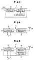
- each transmitter 3 has a transmitter control unit 13, which is, for example, a microcomputer.
- a controller which is the transmitter control unit 13 in the first embodiment, includes, for example, a central processing unit (CPU), a random access memory (RAM), and a read only memory (ROM).
- the transmitter control unit 13 controls the entire operation of the transmitters 3.
- Each transmitter 3 further includes a tire condition sensor, which is a tire pressure sensor 8 in the first embodiment, a transmitting portion, which is a transmission circuit 9 in the first embodiment, an antenna 10, an ID memory 11 that stores a specific ID code, and a receiving portion, which is a reception circuit 12 in the first embodiment.
- the ID codes are identification information specific to each of the transmitters 3 and are used to permit the receiver 4 to identify each of the four transmitters 3 installed in, or associated with, the vehicle 1.
- the tire pressure sensor 8 measures the pressure in the interior of the associated tire and provides the transmitter control unit 13 with pressure data, which is obtained from the measurement.
- the transmitter control unit 13 sends data including the pressure data and the ID code stored in the ID memory 11 to the transmission circuit 9.
- the transmission circuit 9 encodes and modulates the data sent from the transmitter control unit 13.
- the transmission circuit 9 then wirelessly sends a signal including the data by the antenna 10.
- the transmitter control unit 13 of each transmitter 3 controls the pressure sensor 8 to perform measurement at predetermined time intervals (for example, every 15 seconds). Also, the transmitter control unit 13 controls the transmission circuit 9 to perform periodical transmission every time the pressure sensor 8 completes a predetermined number of (for example, 40 cycles of) measurements (a periodical transmission mode). However, when acknowledging an abnormality of the pressure of the associated tire (such as rapid change or decrease of pressure), the transmitter control unit 13 causes the transmission circuit 9 to transmit data immediately regardless of the periodical transmission (an abnormality transmission mode).
- the structure of a signal transmitted from each transmitter 3 in the abnormality transmission mode may differ from the structure of a signal transmitted from each transmitter 3 in the periodical transmission mode. In the first embodiment, the structures of the signals are the same.
- Each transmitter 3 has a battery (not shown), which powers the transmitter 3.
- each transmitter 3 may further include a temperature sensor as the tire condition sensor. The data indicating the detected temperature in the interior of the tire is included in the signal sent from the transmitter 3.
- the reception circuit 12 receives an external signal, or the instruction signal from the commander 5, by the antenna 10.
- the transmitter control unit 13 wirelessly transmits a response signal to the transmission circuit 9 via the antenna 10 (a forced transmission mode).
- the response signal may have any structure as long as the signal includes at least the ID code of the associated transmitter 3.
- the signal has the structure that is the same as that of the transmission signals according to the periodical transmission mode and the abnormality transmission mode.
- the forced transmission mode corresponds to a first transmission mode, in which a response signal is transmitted corresponding to the instruction signal from the commander 5.
- the periodical transmission mode and the abnormality transmission mode correspond to a second transmission mode, in which signals are transmitted regardless of the instruction signal from the commander 5.
- Each transmitter 3 includes a valve stem (not shown) for introducing air into the interior of the tire.
- Each valve stem projects outside the associated tire through the corresponding wheel 2 and can also be used as the antenna 10.
- the receiver 4, which is shown in Fig. 3, is powered by a battery (not shown) installed in the vehicle 1.
- the receiver 4 includes a receiver control unit 18, which is, for example, a microcomputer.
- a controller which is the receiver control unit 18 in the first embodiment, includes, for example, a CPU, an RAM, and an ROM.
- the receiver control unit 18 controls the entire operation of the receiver 4.
- the receiver 4 further includes at least one reception antenna 14, a receiving portion, which is a reception circuit 15 in the first embodiment, a rewritable ID memory 16 for storing the ID code of the four transmitters 3 installed in the vehicle 1, and a commander connecting terminal 17.
- the reception circuit 15 receives a transmission signal from each transmitter 3 via the reception antenna 14.
- the reception circuit 15 demodulates and decodes the received signal to obtain data, which is then transmitted to the receiver control unit 18.
- the receiver control unit 18 obtains the pressure in the interior of the tire associated with the source transmitter 3 based on the data from the reception circuit 15.
- the receiver control unit 18 indicates the information concerning the tire pressure on a display (not shown), which is connected to the receiver 4.
- the display is located in the passenger compartment so that the occupants of the vehicle 1 can see the information shown on the display. The abnormality of the tire pressure may be informed by the display or an alarm separately provided from the display.
- the portable commander (control tool) 5 includes a commander control unit 23, which is, for example, a microcomputer.
- a controller which is the commander control unit 23 in the first embodiment, includes, for example, a CPU, an RAM, and an ROM.
- the commander control unit 23 controls the entire operation of the commander 5.
- the commander 5 further includes an antenna 19, a transmitter, which is a transmission circuit 20 in the first embodiment, an operation switch 7, which is manually operated to transmit an instruction signal to the transmitter 3, a receiver connecting terminal 22.
- the operation switch 7 is, for example, a push-button.
- a cable 6 electrically connects the receiver connecting terminal 22 of the commander 5 to the commander connecting terminal 17 of the receiver 4 (see Fig. 1).
- the cable 6 is detachable from each connecting terminal 17, 22.
- the specific ID code of each transmitter 3 is registered in the receiver 4 as follows. First, the commander 5 is connected to the receiver 4 with the cable 6 as shown in Fig. 1. In this state, the antenna 19 of the commander 5 is placed close to the antenna 10 of a corresponding transmitter 3. The operation switch 7 of the commander 5 is then depressed. The commander control unit 23 transmits an instruction signal to the corresponding transmitter 3 via the transmission circuit 20 and the antenna 19, and sends a signal (ON signal) that indicates the turned-on state of the operation switch 7 to the receiver control unit 18 of the receiver 4 via the cable 6. The ON signal is sent to the receiver 4 only while the operation switch 7 is depressed. The radio field intensity of the instruction signal sent from the commander 5 is relatively weak. Therefore, the transmitters 3 other than the transmitter 3 located close to the antenna 19 of the commander 5 do not receive the instruction signal.
- the transmitter control unit 13 wirelessly transmits a response signal including the ID code stored in the ID memory 11 in response to the instruction signal.
- the receiver control unit 18 receives the response signal via the reception antenna 14 and the reception circuit 15 in a state, in which the ON signal is sent through the cable 6, the receiver control unit 18 registers the ID code included in the response signal in the ID memory 16.
- the above operation is repeated for all four transmitters 3 installed in the vehicle 1.
- the receiver 4 thus registers the ID codes of the transmitters 3.
- the receiver 4 is switched to a registration mode (a first operation mode) for permitting registration of the ID code only when the commander 5 is conveying the turned-on state of the operation switch 7.
- the receiver 4 operates in a monitoring mode (a second operation mode) for monitoring the tire condition when the commander 5 is not conveying the turned-on state of the operation switch 7.
- the receiver control unit 18 of the receiver 4 compares the ID code included in the signal with the ID codes stored in the ID memory 16. When the ID code in the received signal matches with one of the ID codes in the ID memory 16, the receiver control unit 18 continues processing the received signal. That is, the receiver control unit 18 retrieves information such as the pressure data from the received signal and indicates the information concerning the tire condition on the display located in the passenger compartment as required.
- the first embodiment provides the following advantages.
- the ID code of each transmitter 3 is registered in the receiver 4 by only manipulating the operation switch 7 of the commander 5, which is connected to the receiver 4.
- the operation for switching the receiver 4 into the registration mode and the operation for causing the transmitters 3 to transmit the response signal need not be performed separately. This facilitates the registering procedure of the ID codes of the transmitters 3 in the receiver 4.
- the receiver 4 is switched to the registration mode only when the operation switch 7 is depressed.
- Each transmitter 3 transmits a response signal in response to the instruction signal sent in accordance with manipulation of the operation switch 7. Therefore, the transmission of the ID code from the desired transmitter 3 and the registration of the transmitted ID code in the receiver 4 are both performed by the manipulation of the commander 5. Therefore, the ID code of only the desired transmitter 3 is easily and reliably registered in the receiver 4, and the ID code is prevented from being registered in the receiver 4 mistakenly.
- FIG. 5 A second embodiment of the present invention will now be described with reference to Fig. 5.
- the differences from the first embodiment of Figs. 1 to 4 will mainly be discussed below.
- the structure of the commander 5 according to the second embodiment differs from that of the first embodiment.
- the structures of the transmitters 3 and the receiver 4 are the same as those of the first embodiment. Therefore, the second embodiment is described with reference to Figs. 1 to 3 as required.
- the commander 5 of the second embodiment includes the antenna 19, the transmission circuit 20, the operation switch 7, the receiver connecting terminal 22, and the commander control unit 23, which have the same structures as those of the commander 5 shown in Fig. 4.
- the commander 5 of the second embodiment includes a receiving portion, which is a reception circuit 21.
- the reception circuit 21 receives transmission signals from each transmitter 3.
- each transmitter 3 is registered in the receiver 4 as follows. First, the commander 5 is connected to the receiver 4 with the cable 6 as shown in Fig. 1. In this state, the antenna 19 of the commander 5 is placed close to the antenna 10 of a corresponding transmitter 3. The operation switch 7 of the commander 5 is then depressed. The commander control unit 23 transmits an instruction signal to the corresponding transmitter 3 via the transmission circuit 20 and the antenna 19.
- the transmitter control unit 13 On receiving the instruction signal via the antenna 10 and the reception circuit 12, the transmitter control unit 13 wirelessly transmits a response signal including the ID code stored in the ID memory 11 in response to the instruction signal.
- the commander control unit 23 receives the response signal via the antenna 19 and the reception circuit 21.
- the commander control unit 23 transfers the ID code in the received response signal to the receiver control unit 18 via the receiver connecting terminal 22, the cable 6, and the commander connecting terminal 17. Then, the receiver control unit 18 registers the transferred ID code to the ID memory 16.
- the receiver 4 performs registering operation of the ID code transferred via the cable 6 while maintaining the monitoring mode described in the first embodiment. That is, when the transmitter 3 transmits a response signal in response to the instruction signal sent from the commander 5, the response signal is received by not only the commander 5 but also the receiver 4 via the reception antenna 14. At this time, if the commander 5 is not connected to the receiver 4 with the cable 6, the receiver 4 treats the received response signal in the same manner as the signals according to the periodical transmission mode or the signals according to the abnormality transmission mode. That is, when the ID code in the response signal matches with one of the ID codes in the ID memory 16, the receiver 4 retrieves necessary information, such as pressure data, from the response signal. In this case, the receiver 4 does not register the ID code in the wirelessly received response signal to the ID memory 16.
- the receiver 4 When receiving the response signal via the reception antenna 14 in a state, in which the receiver 4 is connected to the commander 5 with the cable 6, the receiver 4 performs the operation according to the monitoring mode in the same manner as when the receiver 4 is not connected to the commander 5. However, the receiver 4 performs the operation for registering the ID code transferred from the commander 5 via the cable 6 in parallel with the operation according to the monitoring mode.
- the second embodiment provides the advantages of the first embodiment shown in Figs. 1 to 4.
- the receiver 4 registers only the ID code transferred from the commander 5 via the cable 6.
- the receiver 4 further prevents the ID code from being registered in the receiver 4 mistakenly.
- the commander 5 need not be connected to the receiver 4 with the cable 6. Instead, radio communication may be established between the receiver 4 and the commander 5. That is, the commander 5 need not be wired to the receiver 4. Instead, the commander 5 may be wirelessly connected to the receiver 4. In this case, the commander 5 wirelessly transmits an ON signal to the receiver 4 based on the manipulation of the operation switch 7.
- the structure of the ON signal may be the same as or different from that of the instruction signal sent to the transmitter 3.
- the commander 5 transmits the ON signal via the antenna 19, or an antenna (not shown) separately arranged from the antenna 19.
- the receiver 4 receives the ON signal from the commander via the reception antenna 14, or an antenna (not shown) separately arranged from the antenna 14. According to this modification, the terminals 22, 17 are omitted from the commander 5 and the receiver 4.
- the commander 5 need not be connected to the receiver 4 with the cable 6. Instead, radio communication may be established between the receiver 4 and the commander 5.
- the commander 5 generates a signal (registration signal) to be transmitted to the receiver 4 based on the response signal received from the transmitter 3, and wirelessly transmits the registration signal to the receiver 4.
- the registration signal includes the ID code in the response signal.
- the receiver 4 stores the ID code in the registration signal in the ID memory 16.
- the commander 5 transmits or receives all signals with a single antenna 19.
- the commander 5 may be provided with a send-only antenna and a receive-only antenna.
- the commander 5 may also be provided with an antenna for communication with the transmitters 3 and an antenna for communication with the receiver 4.
- the receiver 4 receives the registration signal from the commander 5 via the reception antenna 14, or an antenna (not shown) separately arranged from the antenna 14. According to this modification, the terminals 22, 17 are omitted from the commander 5 and the receiver 4.
- the response signals from the transmitters 3 have the same structure as those of the transmission signals according to the periodical transmission mode or the abnormality transmission mode. Instead, each type of signal transmitted from the transmitter 3 may have different structures. Further, information that indicates the type of the signal may be included in the signal sent from the transmitter 3. In this case, when receiving a signal from the transmitter 3, the receiver 4 and the commander 5 accurately determine the type of the received signal. Therefore, the process according to the type of the received signal is accurately performed.
Landscapes
- Engineering & Computer Science (AREA)
- Mechanical Engineering (AREA)
- Arrangements For Transmission Of Measured Signals (AREA)
Claims (6)
- Appareil destiné à surveiller l'état d'un pneu monté sur un véhicule, l'appareil comprenant :dans lequel le récepteur présente un premier mode de fonctionnement, qui permet l'enregistrement des données d'identification, et un second mode de fonctionnement, qui ne permet pas l'enregistrement des données d'identification, dans lequel, quand le dispositif de commande transfère l'état allumé du commutateur de fonctionnement au récepteur, le récepteur est actionné dans le premier mode de fonctionnement, et dans lequel quand les données d'identification dans un signal reçu depuis l'émetteur correspondent aux données d'identification dans la mémoire alors que le récepteur est dans le second mode de fonctionnement, le récepteur continue de traiter le signal reçu.un dispositif de commande dans lequel le dispositif de commande comprend un commutateur de fonctionnement et dans lequel le dispositif de commande transmet un signal d'instruction quand le commutateur de fonctionnement est allumé ;un émetteur fixé au pneu, dans lequel l'émetteur comprend un détecteur d'état de pneu, qui détecte l'état du pneu, une partie de réception, qui reçoit le signal d'instruction, et une partie de transmission, qui transmet un signal de réponse lors de la réception du signal d'instruction, le signal de réponse comprenant une donnée d'identification spécifique donnée à l'émetteur par avance ; etun récepteur situé dans la carrosserie du véhicule, dans lequel le récepteur comprend une partie de réception, qui reçoit un signal transmis depuis l'émetteur, et une mémoire d'identification réinscriptible qui stocke les données d'identification de l'émetteur, dans lequel quand le commutateur de fonctionnement est allumé, le dispositif de commande transfère l'état allumé du commutateur de fonctionnement au récepteur, caractérisé en ce que, lors de la réception du signal de réponse depuis l'émetteur, le dispositif de commande transfère l'état allumé du commutateur de fonctionnement au récepteur, le récepteur stocke les données d'identification dans le signal de réponse dans la mémoire d'identification, dans lequel l'émetteur présente un premier mode de transmission, dans lequel le signal de réponse est transmis en réponse au signal d'instruction depuis le dispositif de commande, et un second mode de transmission, dans lequel un signal est transmis sans tenir compte du signal d'instruction depuis le dispositif de commande, et dans lequel le signal transmis selon le second mode de transmission comprend au moins des données indiquant l'état du pneu détecté par le détecteur d'état du pneu et les données d'identification,
- Appareil selon la revendication 1, caractérisé en ce que le récepteur peut être relié au dispositif de commande avec un câble, et dans lequel le dispositif de commande envoie un signal EN MARCHE indiquant l'état allumé du commutateur de fonctionnement vers le récepteur par l'intermédiaire du câble.
- Appareil selon l'une quelconque des revendications 1 ou 2, caractérisé en ce que le dispositif de commande est portable.
- Appareil destiné à surveiller l'état d'un pneu monté sur un véhicule, l'appareil comprenant :le dispositif de commande comprend une partie de réception, qui reçoit le signal de réponse depuis l'émetteur, dans lequel, lors de la réception du signal de réponse, le dispositif de commande envoie les données d'identification dans le signal de réponse vers le récepteur, et dans lequel, lors de la réception des données d'identification envoyées depuis le dispositif de commande, le récepteur stocke les données d'identification dans la mémoire d'identification, caractérisé en ce que, l'émetteur présente un premier mode de transmission, dans lequel le signal de réponse est transmis en réponse au signal d'instruction depuis le dispositif de commande, et un second mode de transmission, dans lequel un signal est transmis sans tenir compte du signal d'instruction depuis le dispositif de commande, et dans lequel le signal transmis selon le second mode de transmission comprend au moins des données indiquant l'état du pneu détecté par le détecteur d'état du pneu et les données d'identification,un dispositif de commande dans lequel le dispositif de commande comprend un commutateur de fonctionnement et dans lequel le dispositif de commande transmet un signal d'instruction quand le commutateur de fonctionnement est allumé ;un émetteur fixé au pneu, dans lequel l'émetteur comprend un détecteur d'état de pneu, qui détecte l'état du pneu, une partie de réception, qui reçoit le signal d'instruction, et une partie de transmission, qui transmet un signal de réponse lors de la réception du signal d'instruction, le signal de réponse comprenant une donnée d'identification spécifique donnée à l'émetteur par avance ; etun récepteur situé dans la carrosserie du véhicule, dans lequel le récepteur comprend une partie de réception, qui reçoit un signal transmis depuis l'émetteur, et une mémoire d'identification réinscriptible qui stocke les données d'identification de l'émetteur, dans lequel
dans lequel le récepteur présente un mode de surveillance pour surveiller l'état du pneu, dans lequel, lors de la réception d'un signal depuis l'émetteur alors que le récepteur est dans le mode de surveillance, le récepteur continue de traiter le signal reçu si les données d'identification dans le signal reçu correspondent aux données d'identification envoyées depuis le dispositif de commande alors que le récepteur est dans le mode de surveillance, le récepteur stocke les données d'identification dans la mémoire d'identification. - Appareil selon la revendication 4 caractérisé en ce que le récepteur peut être relié au dispositif de commande avec un câble et dans lequel, lorsqu'il reçoit le signal de réponse de l'émetteur, le dispositif de commande transfère les données d'identification dans le signal de réponse au récepteur via le câble.
- Appareil selon l'une quelconque des revendications 4 ou 5, caractérisé en ce que le dispositif de commande est portable.
Applications Claiming Priority (4)
| Application Number | Priority Date | Filing Date | Title |
|---|---|---|---|
| JP2001387712 | 2001-12-20 | ||
| JP2001387712 | 2001-12-20 | ||
| JP2002009919 | 2002-01-18 | ||
| JP2002009919 | 2002-01-18 |
Publications (2)
| Publication Number | Publication Date |
|---|---|
| EP1323552A1 EP1323552A1 (fr) | 2003-07-02 |
| EP1323552B1 true EP1323552B1 (fr) | 2004-12-08 |
Family
ID=26625177
Family Applications (1)
| Application Number | Title | Priority Date | Filing Date |
|---|---|---|---|
| EP02028531A Expired - Lifetime EP1323552B1 (fr) | 2001-12-20 | 2002-12-19 | Appareil pour surveiller des conditions des pneus |
Country Status (3)
| Country | Link |
|---|---|
| US (1) | US6804999B2 (fr) |
| EP (1) | EP1323552B1 (fr) |
| DE (1) | DE60202186T2 (fr) |
Families Citing this family (30)
| Publication number | Priority date | Publication date | Assignee | Title |
|---|---|---|---|---|
| US7161476B2 (en) | 2000-07-26 | 2007-01-09 | Bridgestone Firestone North American Tire, Llc | Electronic tire management system |
| US8266465B2 (en) | 2000-07-26 | 2012-09-11 | Bridgestone Americas Tire Operation, LLC | System for conserving battery life in a battery operated device |
| JP3873857B2 (ja) * | 2002-09-27 | 2007-01-31 | 株式会社デンソー | タイヤ空気圧監視装置のセンサid登録方法 |
| JP3931811B2 (ja) * | 2003-01-09 | 2007-06-20 | 株式会社デンソー | タイヤ空気圧監視装置のセンサid登録方法 |
| US6750761B1 (en) * | 2003-02-25 | 2004-06-15 | Delphi Technologies, Inc. | Method for monitoring tire parameters |
| US6941801B2 (en) * | 2003-12-19 | 2005-09-13 | Lear Corporation | Tire pressure monitoring system |
| CN1798045A (zh) * | 2004-12-30 | 2006-07-05 | 鸿富锦精密工业(深圳)有限公司 | 便携式显示装置及方法 |
| JP4812432B2 (ja) * | 2006-01-10 | 2011-11-09 | 株式会社ブリヂストン | タイヤ点検装置、タイヤ点検システム及びタイヤ点検方法 |
| US7639122B2 (en) * | 2006-10-30 | 2009-12-29 | Spx Corporation | Tire pressure monitor system tool with vehicle entry system |
| US7592903B2 (en) * | 2006-10-30 | 2009-09-22 | Spx Corporation | Tire pressure monitor system tool with re-learn and diagnostic procedures |
| US7592904B2 (en) * | 2006-10-30 | 2009-09-22 | Spx Corporation | Tire pressure monitor system module |
| US7623025B2 (en) * | 2006-10-30 | 2009-11-24 | Spx Corporation | Tire pressure monitor initiation tool with vehicle data interface |
| WO2009006518A1 (fr) | 2007-07-03 | 2009-01-08 | Continental Automotive Systems Us, Inc. | Capteur universel de contrôle de pression de pneu |
| US8352911B2 (en) * | 2007-11-21 | 2013-01-08 | Teradata Us, Inc. | Techniques for constructing and using run-time JAVA archives (JAR) for JAVA Stored Procedures (JSPS) |
| US7884707B2 (en) * | 2008-04-23 | 2011-02-08 | Spx Corporation | Tire pressure monitor system tool with parts number database |
| US8751092B2 (en) | 2011-01-13 | 2014-06-10 | Continental Automotive Systems, Inc. | Protocol protection |
| US8610552B2 (en) | 2011-03-31 | 2013-12-17 | Honda Motor Co., Ltd. | Tire pressure monitoring system initialization using moving antenna |
| US9676238B2 (en) | 2011-08-09 | 2017-06-13 | Continental Automotive Systems, Inc. | Tire pressure monitor system apparatus and method |
| KR101599780B1 (ko) | 2011-08-09 | 2016-03-04 | 컨티넨탈 오토모티브 시스템즈 인코포레이티드 | 타이어 압력 모니터링 시스템을 위한 프로토콜 오해 회피 장치 및 방법 |
| CN103717416B (zh) | 2011-08-09 | 2019-02-22 | 大陆汽车系统公司 | 轮胎压力监控设备和方法 |
| CN103874592B (zh) * | 2011-08-09 | 2018-01-30 | 大陆汽车系统公司 | 用于激活轮胎压力监控器的定位过程的设备和方法 |
| KR101599365B1 (ko) * | 2011-08-09 | 2016-03-14 | 컨티넨탈 오토모티브 시스템즈 인코포레이티드 | 타이어 압력 모니터링 시스템에서 프로토콜 배열 |
| DE112012004481B4 (de) | 2011-10-26 | 2019-04-18 | Ateq Corporation | Universelles Werkzeug und Verfahren für ein Reifendrucküberwachungssystem |
| US9091537B2 (en) | 2012-04-18 | 2015-07-28 | Bosch Automotive Service Solutions Inc. | Tire pressure monitor system tool with active tire pressure display |
| NO2833907T3 (fr) * | 2012-11-02 | 2018-07-28 | ||
| US9446636B2 (en) | 2014-02-26 | 2016-09-20 | Continental Automotive Systems, Inc. | Pressure check tool and method of operating the same |
| US9517664B2 (en) | 2015-02-20 | 2016-12-13 | Continental Automotive Systems, Inc. | RF transmission method and apparatus in a tire pressure monitoring system |
| DE102016213290A1 (de) | 2015-08-03 | 2017-02-09 | Continental Automotive Systems, Inc. | Vorrichtung, System und Verfahren zum Konfigurieren eines Reifeninformationssensors mit einem Übertragungsprotokoll auf der Basis von Fahrzeugtriggerkenngrößen |
| US11400772B2 (en) | 2020-02-26 | 2022-08-02 | Ateq | Scanning method and device for tire pressure monitoring system (tpms) protocols |
| FR3109850B1 (fr) | 2020-04-29 | 2022-12-30 | Ateq | Dispositif pour systeme electronique de controle de la pression des pneus d’un vehicule automobile |
Family Cites Families (6)
| Publication number | Priority date | Publication date | Assignee | Title |
|---|---|---|---|---|
| DE4205911A1 (de) | 1992-02-26 | 1993-09-02 | Uwatec Ag | Kontrollvorrichtung fuer den luftdruck von luftbereiften fahrzeugraedern |
| US6062072A (en) * | 1995-08-11 | 2000-05-16 | Dynatron Ag | Device for monitoring the air pressure of pneumatic tires of vehicles |
| DE19632150B4 (de) * | 1996-08-09 | 2004-06-09 | Conti Temic Microelectronic Gmbh | Verfahren zur Kontrolle des Luftdrucks in den Reifen von Kraftfahrzeugrädern |
| JP2000153703A (ja) * | 1998-11-19 | 2000-06-06 | Pacific Ind Co Ltd | タイヤ空気圧警報装置及び送信信号を任意に操作できる制御治具 |
| US6710708B2 (en) * | 1999-02-05 | 2004-03-23 | Schrader-Bridgeport International, Inc. | Method and apparatus for a remote tire pressure monitoring system |
| JP2001108551A (ja) * | 1999-10-13 | 2001-04-20 | Pacific Ind Co Ltd | タイヤ空気圧監視装置及び外部通信装置 |
-
2002
- 2002-12-19 EP EP02028531A patent/EP1323552B1/fr not_active Expired - Lifetime
- 2002-12-19 DE DE60202186T patent/DE60202186T2/de not_active Expired - Fee Related
- 2002-12-20 US US10/327,406 patent/US6804999B2/en not_active Expired - Fee Related
Also Published As
| Publication number | Publication date |
|---|---|
| DE60202186T2 (de) | 2005-12-08 |
| US6804999B2 (en) | 2004-10-19 |
| US20030121320A1 (en) | 2003-07-03 |
| DE60202186D1 (de) | 2005-01-13 |
| EP1323552A1 (fr) | 2003-07-02 |
Similar Documents
| Publication | Publication Date | Title |
|---|---|---|
| EP1323552B1 (fr) | Appareil pour surveiller des conditions des pneus | |
| EP1336512B1 (fr) | Appareil de surveillance de condition de pneumatique | |
| EP1306234B1 (fr) | Appareil de surveillance de l'état d'un pneumatique | |
| EP1092568B1 (fr) | Appareil de contrôle de la pression de l'air de pneumatiques et appareil de communication externe | |
| US6788193B2 (en) | System and method for tire pressure monitoring providing automatic tire location recognition | |
| US6414592B1 (en) | Tire condition sensor communication with tire location provided via manually inputted update | |
| US6983649B2 (en) | Tire condition monitoring apparatus | |
| US8144023B2 (en) | Tire inflation pressure detecting apparatus capable of triggering only selected transceiver to perform task | |
| US7705714B2 (en) | Wheel position detecting device that performs dedicated local communication for each wheel and tire air pressure detecting device including the same | |
| US7253726B2 (en) | Tire condition monitoring apparatus, transmitter, and receiver | |
| EP1319531A2 (fr) | Appareil et méthode pour la surveillance de l'état des pneumatiques | |
| WO2004038674A1 (fr) | Systeme de surveillance de pneus et recepteur de surveillance, dispositif de surveillance et capteur utilises dans ledit systeme | |
| EP1428693B1 (fr) | Transpondeur pour appareil de surveillance de condition de pneumatique | |
| US6999861B2 (en) | Tire status monitoring apparatus and receiver therefor | |
| EP1270276B1 (fr) | Appareil de surveillance de condition de pneumatique | |
| US10086661B2 (en) | Tire condition detecting appartus | |
| GB2385927A (en) | Automatic tire location recognition using temperature and rotation direction data | |
| JP3401535B2 (ja) | タイヤ空気圧監視システム | |
| JP3945578B2 (ja) | タイヤ状態監視装置 | |
| US8049606B2 (en) | Method for assigning identification codes in radio signals from tire pressure monitoring devices on vehicle wheels to the wheel position and vehicle equipped for this method | |
| US20090243829A1 (en) | Apparatus and process for monitoring a vehicle condition | |
| JP2003276410A (ja) | タイヤ状態監視装置 | |
| JP2000153703A (ja) | タイヤ空気圧警報装置及び送信信号を任意に操作できる制御治具 |
Legal Events
| Date | Code | Title | Description |
|---|---|---|---|
| PUAI | Public reference made under article 153(3) epc to a published international application that has entered the european phase |
Free format text: ORIGINAL CODE: 0009012 |
|
| AK | Designated contracting states |
Designated state(s): AT BE BG CH CY CZ DE DK EE ES FI FR GB GR IE IT LI LU MC NL PT SE SI SK TR |
|
| AX | Request for extension of the european patent |
Extension state: AL LT LV MK RO |
|
| 17P | Request for examination filed |
Effective date: 20030623 |
|
| 17Q | First examination report despatched |
Effective date: 20031009 |
|
| AKX | Designation fees paid |
Designated state(s): DE FR GB |
|
| GRAP | Despatch of communication of intention to grant a patent |
Free format text: ORIGINAL CODE: EPIDOSNIGR1 |
|
| GRAS | Grant fee paid |
Free format text: ORIGINAL CODE: EPIDOSNIGR3 |
|
| GRAA | (expected) grant |
Free format text: ORIGINAL CODE: 0009210 |
|
| AK | Designated contracting states |
Kind code of ref document: B1 Designated state(s): DE FR GB |
|
| REG | Reference to a national code |
Ref country code: GB Ref legal event code: FG4D |
|
| REG | Reference to a national code |
Ref country code: IE Ref legal event code: FG4D |
|
| REF | Corresponds to: |
Ref document number: 60202186 Country of ref document: DE Date of ref document: 20050113 Kind code of ref document: P |
|
| ET | Fr: translation filed | ||
| PLBE | No opposition filed within time limit |
Free format text: ORIGINAL CODE: 0009261 |
|
| STAA | Information on the status of an ep patent application or granted ep patent |
Free format text: STATUS: NO OPPOSITION FILED WITHIN TIME LIMIT |
|
| 26N | No opposition filed |
Effective date: 20050909 |
|
| PGFP | Annual fee paid to national office [announced via postgrant information from national office to epo] |
Ref country code: GB Payment date: 20071218 Year of fee payment: 6 |
|
| PGFP | Annual fee paid to national office [announced via postgrant information from national office to epo] |
Ref country code: DE Payment date: 20071221 Year of fee payment: 6 |
|
| PGFP | Annual fee paid to national office [announced via postgrant information from national office to epo] |
Ref country code: FR Payment date: 20071217 Year of fee payment: 6 |
|
| GBPC | Gb: european patent ceased through non-payment of renewal fee |
Effective date: 20081219 |
|
| REG | Reference to a national code |
Ref country code: FR Ref legal event code: ST Effective date: 20090831 |
|
| PG25 | Lapsed in a contracting state [announced via postgrant information from national office to epo] |
Ref country code: DE Free format text: LAPSE BECAUSE OF NON-PAYMENT OF DUE FEES Effective date: 20090701 |
|
| PG25 | Lapsed in a contracting state [announced via postgrant information from national office to epo] |
Ref country code: GB Free format text: LAPSE BECAUSE OF NON-PAYMENT OF DUE FEES Effective date: 20081219 |
|
| PG25 | Lapsed in a contracting state [announced via postgrant information from national office to epo] |
Ref country code: FR Free format text: LAPSE BECAUSE OF NON-PAYMENT OF DUE FEES Effective date: 20081231 |