US6668657B2 - Pressure sensor - Google Patents
Pressure sensor Download PDFInfo
- Publication number
- US6668657B2 US6668657B2 US09/922,454 US92245401A US6668657B2 US 6668657 B2 US6668657 B2 US 6668657B2 US 92245401 A US92245401 A US 92245401A US 6668657 B2 US6668657 B2 US 6668657B2
- Authority
- US
- United States
- Prior art keywords
- diaphragm
- base
- sensor
- pressure
- sealing cap
- Prior art date
- Legal status (The legal status is an assumption and is not a legal conclusion. Google has not performed a legal analysis and makes no representation as to the accuracy of the status listed.)
- Expired - Fee Related
Links
Images

Classifications
-
- G—PHYSICS
- G01—MEASURING; TESTING
- G01L—MEASURING FORCE, STRESS, TORQUE, WORK, MECHANICAL POWER, MECHANICAL EFFICIENCY, OR FLUID PRESSURE
- G01L19/00—Details of, or accessories for, apparatus for measuring steady or quasi-steady pressure of a fluent medium insofar as such details or accessories are not special to particular types of pressure gauges
- G01L19/0061—Electrical connection means
- G01L19/0084—Electrical connection means to the outside of the housing
-
- G—PHYSICS
- G01—MEASURING; TESTING
- G01L—MEASURING FORCE, STRESS, TORQUE, WORK, MECHANICAL POWER, MECHANICAL EFFICIENCY, OR FLUID PRESSURE
- G01L19/00—Details of, or accessories for, apparatus for measuring steady or quasi-steady pressure of a fluent medium insofar as such details or accessories are not special to particular types of pressure gauges
- G01L19/14—Housings
- G01L19/142—Multiple part housings
-
- G—PHYSICS
- G01—MEASURING; TESTING
- G01L—MEASURING FORCE, STRESS, TORQUE, WORK, MECHANICAL POWER, MECHANICAL EFFICIENCY, OR FLUID PRESSURE
- G01L9/00—Measuring steady of quasi-steady pressure of fluid or fluent solid material by electric or magnetic pressure-sensitive elements; Transmitting or indicating the displacement of mechanical pressure-sensitive elements, used to measure the steady or quasi-steady pressure of a fluid or fluent solid material, by electric or magnetic means
- G01L9/0041—Transmitting or indicating the displacement of flexible diaphragms
- G01L9/007—Transmitting or indicating the displacement of flexible diaphragms using variations in inductance
-
- G—PHYSICS
- G01—MEASURING; TESTING
- G01L—MEASURING FORCE, STRESS, TORQUE, WORK, MECHANICAL POWER, MECHANICAL EFFICIENCY, OR FLUID PRESSURE
- G01L9/00—Measuring steady of quasi-steady pressure of fluid or fluent solid material by electric or magnetic pressure-sensitive elements; Transmitting or indicating the displacement of mechanical pressure-sensitive elements, used to measure the steady or quasi-steady pressure of a fluid or fluent solid material, by electric or magnetic means
- G01L9/14—Measuring steady of quasi-steady pressure of fluid or fluent solid material by electric or magnetic pressure-sensitive elements; Transmitting or indicating the displacement of mechanical pressure-sensitive elements, used to measure the steady or quasi-steady pressure of a fluid or fluent solid material, by electric or magnetic means involving the displacement of magnets, e.g. electromagnets
Definitions
- the invention relates to a pressure sensor for a motor vehicle having a sensor element arranged in a sensor housing, a base connected with the sensor housing, a pressure space defined by the base and a diaphragm which is held via a sealed connection to the base, a pressure bore extending through base to the pressure pressure space, and an actuating element arranged on a side of the diaphragm facing away from the pressure space for non-contact actuation of the sensor element.
- Pressure sensors having diaphragms with actuators arranged thereon on a side facing away from a pressure space are used in technology for various tasks and are generally known. Where such pressure sensors are concerned, it is often important to prevent leaks, even after lengthy use. This prevention of leaks is required when the medium acting upon the pressure sensor is a medium such as, for example, hydraulic fluid that is harmful to the immediate surroundings of the pressure sensor or to the environment or when the medium is a flammable medium such as, for example, fuel. In a motor vehicle, the escape of fuel from a pressure sensor increases the risk of fire. Even if the the medium is not harmful or flammable, the medium escaping from pressure sensors may damage control devices or make them temporarily inoperative.
- the diaphragm is a critical component in terms of leakage, because the diaphragm may break as a result of frequent actuation or even due to a material fault, thus resulting in a sudden serious leak.
- the pressure sensor could be provided with cladding, in a similar way to the double-walled cladding of oil tanks to be installed in the ground.
- cladding is costly and not entirely reliable, however, because electrical leads would have to be led sealingly out of it and the cladding would also have to be sealed off relative to the base of the pressure sensor.
- the object is met by a pressure sensor having a diaphragm and an actuating element that are surrounded by a sealing cap connected sealingly to the base of the pressure sensor housing.
- the sealing cap defines a further pressuretight shutoff of the pressure space arranged behind the diaphragm. Since this further shutoff of the pressure space is only required to surround the pressure space and the actuating element, the further shutoff of the pressure space can be made relatively small, so that it does not appreciably increase either the costs of the pressure sensor or its construction volume.
- the sealing cap may be designed in the form of a hat with a flange which faces one side of the diaphragm with a clearance therebetween such that the flange limits the maximum flexion of the diaphragm.
- the sealing connection of the sealing cap is made to the base.
- a middle region of the sealing cap has a cylinder leading over the actuating element.
- This configuration of the sealing cap has a double function. The first function is to ensure the prevention of leaks in the event of a failure of the diaphragm and the second function is to limit the maximum bulge of the diaphragm under high pressure. Accordingly, the sealing cap prevents overstretching and breaking of the diaphragm even during the occurrence of pressure peaks.
- the actuating element of the pressure sensor may be a magnet and the sensor element a Hall effect device and the sealing cap may consist of a nonmagnetic material.
- the flexion of the diaphragm may also be measured in another non-contact way such as, for example inductively or capacitively.
- the diaphragm and the sealing cap may be made from high-grade steel so that the pressure sensor may be cost-effectively produced and so that the pressure sensor can withstand even aggressive media without the risk of corrosion.
- the sealing cap may be connected via a sealed connection to the diaphragm and the base particularly cost-effectively when the sealing cap is connected to the diaphragm and the base by welding.
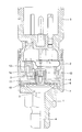
- the drawing is a longitudinal sectional view of a pressure sensor according to an embodiment of the present invention.
- the pressure sensor includes a base 1 via which the pressure sensor may be screwed into a threaded bore, not shown.
- a sensor housing 2 arranged so that the base 1 and a contact part 3 are held by the sensor housing 2 .
- the contact part 3 sealingly closes an upper part of the sensor housing 2 and includes an electrical connection device such as a conventional bayonet plug via which the pressure sensor acquires its necessary electrical connections.
- a pressure bore 4 is arranged through the base 1 to a pressure space 5 which is formed by a recess in the upper end face of the base 1 and which is delimited laterally in the upper region of the base 1 by a peripheral shoulder 6 of the base 1 .
- the shoulder 6 is connected to the edge of an elastic diaphragm 7 covering the pressure space 5 .
- a spacer element 8 is seated on a side of the diaphragm 7 which faces away from the pressure space 5 .
- An actuating element 9 comprising a magnet is held in the spacer element 8 .
- a sealing cap 10 in the shape of a hat is arranged over the diaphragm 7 and the spacer element S.
- the sealing cap 10 includes a flange 11 (i.e., the brim of the hat) and a cylinder 12 .
- the flange 11 rests on the diaphragm 7 in the region of the shoulder 6 .
- a clearance is defined between the at rest position of the diaphragm 7 and the flange 11 such that the maximum flexion of the diaphragm during operation is limited by the flange 11 .
- the base 1 , the diaphragm 7 , and sealing cap 10 may be made of high-grade steel so that the flange 11 is sealingly connected to the diaphragm 7 and the shoulder 6 of the base 1 via a peripheral welded joint.
- the cylinder 12 of the sealing cap 10 surrounds the spacer element 8 and the actuating element 9 .
- a sensor element 14 is arranged in a carrier 13 in the sensor housing 2 .
- the sensor element 14 may, for example, comprise a conventional Hall effect device for detecting the position of the actuating element 9 which is a magnet.
- the diaphragm 7 bulges upward elastically to a greater or lesser extent as a function of the pressure.
- the spacer element 8 together with the actuating element 9 thereby move to a corresponding extent.
- the movement is detected by the sensor element 14 , that is to say the Hall effect device, thereby generating a pressure-dependent sensor signal.
- the measurement medium only comes up against the sealing cap 10 . Leakage of the measurement medium from the sensor is thereby prevented by the sealed connection between the flange 11 , the elastic diaphragm 7 , and the peripheral shoulder 6 of the base 1 .
Landscapes
- Physics & Mathematics (AREA)
- General Physics & Mathematics (AREA)
- Electromagnetism (AREA)
- Measuring Fluid Pressure (AREA)
Applications Claiming Priority (3)
| Application Number | Priority Date | Filing Date | Title |
|---|---|---|---|
| DE10039609.7 | 2000-08-09 | ||
| DE10039609A DE10039609A1 (de) | 2000-08-09 | 2000-08-09 | Drucksensor |
| DE10039609 | 2000-08-09 |
Publications (2)
| Publication Number | Publication Date |
|---|---|
| US20020020222A1 US20020020222A1 (en) | 2002-02-21 |
| US6668657B2 true US6668657B2 (en) | 2003-12-30 |
Family
ID=7652337
Family Applications (1)
| Application Number | Title | Priority Date | Filing Date |
|---|---|---|---|
| US09/922,454 Expired - Fee Related US6668657B2 (en) | 2000-08-09 | 2001-08-03 | Pressure sensor |
Country Status (3)
| Country | Link |
|---|---|
| US (1) | US6668657B2 (de) |
| EP (1) | EP1184650A1 (de) |
| DE (1) | DE10039609A1 (de) |
Cited By (2)
| Publication number | Priority date | Publication date | Assignee | Title |
|---|---|---|---|---|
| US20070028697A1 (en) * | 2005-08-08 | 2007-02-08 | Honeywell International Inc. | One piece needle and diaphragm assembly |
| US20090050466A1 (en) * | 2007-08-21 | 2009-02-26 | Michael Andrew Kozan | Non-contact pressure switch assembly |
Families Citing this family (8)
| Publication number | Priority date | Publication date | Assignee | Title |
|---|---|---|---|---|
| US7577583B2 (en) | 2001-08-09 | 2009-08-18 | Acushnet Company | Computerized article customization system and method for use thereof |
| DE10163164B4 (de) * | 2001-12-20 | 2004-02-19 | Siemens Ag | Drucksensor |
| JP3976015B2 (ja) | 2004-02-04 | 2007-09-12 | 株式会社デンソー | 圧力センサ |
| DE102005016812B3 (de) * | 2005-04-07 | 2006-12-21 | Fachhochschule Koblenz | Vorrichtung zur Messung eines Drucks in einem Strömungskanal |
| DE102008022465A1 (de) * | 2007-05-12 | 2008-11-13 | Marquardt Gmbh | Sensor |
| DE102012205138B3 (de) * | 2012-03-29 | 2013-03-07 | Siemens Aktiengesellschaft | Druckschalteinrichtung mit einem Magnetschalter und einer Einrichtung zur Diagnose des Magnetschalters |
| US11541255B2 (en) * | 2016-09-29 | 2023-01-03 | Honeywell International Inc. | Custom-controllable powered respirator face mask |
| JP6968121B2 (ja) * | 2019-04-26 | 2021-11-17 | 株式会社鷺宮製作所 | 圧力センサ |
Citations (10)
| Publication number | Priority date | Publication date | Assignee | Title |
|---|---|---|---|---|
| US3989911A (en) | 1975-09-05 | 1976-11-02 | Perry Joseph A | Magnetic differential pressure switch |
| US4735090A (en) * | 1986-11-28 | 1988-04-05 | Honeywell Inc. | Flange mounted pressure transmitter |
| GB2247316A (en) | 1990-07-21 | 1992-02-26 | Bailey & Mackey Limited | Pressure sensor utilising Hall-effect device |
| EP0676785A2 (de) | 1994-04-06 | 1995-10-11 | FILTERWERK MANN & HUMMEL GMBH | Differenzdruckschalter |
| US5652391A (en) * | 1995-05-12 | 1997-07-29 | Furon Company | Double-diaphragm gauge protector |
| US5734109A (en) * | 1995-06-14 | 1998-03-31 | Itm, Ute Thanscheidt | Indicator device |
| US6120458A (en) * | 1999-01-07 | 2000-09-19 | Welch Allyn, Inc. | Low profile pressure measure device |
| US6255609B1 (en) * | 2000-06-26 | 2001-07-03 | Predator Systems, Inc. | High pressure resistant, low pressure actuating sensors |
| US20010015105A1 (en) * | 2000-02-22 | 2001-08-23 | Endress + Hauser Gmbh + Co. | Pressure sensor |
| US20020023500A1 (en) * | 2000-08-25 | 2002-02-28 | Kenji Chikuan | Pressure sensor having semiconductor sensor chip |
Family Cites Families (4)
| Publication number | Priority date | Publication date | Assignee | Title |
|---|---|---|---|---|
| DE3104379A1 (de) * | 1981-02-07 | 1982-08-19 | Moto Meter Ag, 7250 Leonberg | Druckmesser mit elektro-mechanischem wandler |
| DE3436493A1 (de) * | 1984-10-05 | 1986-04-10 | Dieter 3502 Vellmar Coesfeld | Druckmessvorrichtung zur kontinuierlichen ueberwachung des luftdruckes in fahrzeugreifen |
| DE8803297U1 (de) * | 1988-03-11 | 1988-04-28 | Armaturenfabrik Hermann Voss GmbH + Co, 5272 Wipperfürth | Druckbetätigter, elektrischer Schalter, insbesondere Bremslichtschalter |
| US4936148A (en) * | 1988-10-17 | 1990-06-26 | Anent Systems Corporation | Hall effect pressure transducer |
-
2000
- 2000-08-09 DE DE10039609A patent/DE10039609A1/de not_active Withdrawn
-
2001
- 2001-06-12 EP EP01114178A patent/EP1184650A1/de not_active Withdrawn
- 2001-08-03 US US09/922,454 patent/US6668657B2/en not_active Expired - Fee Related
Patent Citations (11)
| Publication number | Priority date | Publication date | Assignee | Title |
|---|---|---|---|---|
| US3989911A (en) | 1975-09-05 | 1976-11-02 | Perry Joseph A | Magnetic differential pressure switch |
| US4735090A (en) * | 1986-11-28 | 1988-04-05 | Honeywell Inc. | Flange mounted pressure transmitter |
| GB2247316A (en) | 1990-07-21 | 1992-02-26 | Bailey & Mackey Limited | Pressure sensor utilising Hall-effect device |
| EP0676785A2 (de) | 1994-04-06 | 1995-10-11 | FILTERWERK MANN & HUMMEL GMBH | Differenzdruckschalter |
| US5602373A (en) | 1994-04-06 | 1997-02-11 | Filterwerk Mann & Hummel Gmbh | Differential pressure switch with an adjusting piston driven by a restoring spring for an oil-separating air filter |
| US5652391A (en) * | 1995-05-12 | 1997-07-29 | Furon Company | Double-diaphragm gauge protector |
| US5734109A (en) * | 1995-06-14 | 1998-03-31 | Itm, Ute Thanscheidt | Indicator device |
| US6120458A (en) * | 1999-01-07 | 2000-09-19 | Welch Allyn, Inc. | Low profile pressure measure device |
| US20010015105A1 (en) * | 2000-02-22 | 2001-08-23 | Endress + Hauser Gmbh + Co. | Pressure sensor |
| US6255609B1 (en) * | 2000-06-26 | 2001-07-03 | Predator Systems, Inc. | High pressure resistant, low pressure actuating sensors |
| US20020023500A1 (en) * | 2000-08-25 | 2002-02-28 | Kenji Chikuan | Pressure sensor having semiconductor sensor chip |
Non-Patent Citations (1)
| Title |
|---|
| J. Böettcher, "Software korrigiert Drucksensor" Jul. 21, 1989, pp. 38-42. |
Cited By (2)
| Publication number | Priority date | Publication date | Assignee | Title |
|---|---|---|---|---|
| US20070028697A1 (en) * | 2005-08-08 | 2007-02-08 | Honeywell International Inc. | One piece needle and diaphragm assembly |
| US20090050466A1 (en) * | 2007-08-21 | 2009-02-26 | Michael Andrew Kozan | Non-contact pressure switch assembly |
Also Published As
| Publication number | Publication date |
|---|---|
| DE10039609A1 (de) | 2002-02-21 |
| EP1184650A1 (de) | 2002-03-06 |
| US20020020222A1 (en) | 2002-02-21 |
Similar Documents
| Publication | Publication Date | Title |
|---|---|---|
| US6668657B2 (en) | Pressure sensor | |
| KR102759514B1 (ko) | 압력 릴리프 장치 및 이러한 압력 릴리프 장치를 포함하는 배터리 하우징 | |
| JP6622833B2 (ja) | 自動車両分野におけるハウジング用緊急脱気装置 | |
| JPH03504633A (ja) | 液圧ラムのためのシール | |
| JP6417473B2 (ja) | 金属プロセスシールのためのプロセス分離ダイヤフラムアセンブリ | |
| CN103728092B (zh) | 用于高压存储设备的压力表 | |
| US20220403935A1 (en) | Seal assembly and seal element | |
| JP2011503450A5 (de) | ||
| US4167201A (en) | Pressure accumulator with failure indicator | |
| CN104595282A (zh) | 一种内置磁致伸缩位移传感器的液压油缸 | |
| KR101625645B1 (ko) | 배관 수압 테스트용 블라인드 플랜지 | |
| US11193842B2 (en) | Pressure sensor assemblies with protective pressure feature of a pressure mitigation element | |
| US9032805B2 (en) | High pressure visual indicator | |
| US10077104B2 (en) | Proximity sensor for aircraft and having a hydraulic fuse | |
| CN102445302B (zh) | 一种压力传感器 | |
| US7373827B2 (en) | High-pressure sensor with sealing system | |
| US2503594A (en) | Pressure responsive actuator | |
| JPH09105466A (ja) | グランドパッキンシール診断装置 | |
| US10533669B2 (en) | Bi-directional flow control valve | |
| US20050126297A1 (en) | Pressure sensor element having an integrated sealing surface | |
| KR101519161B1 (ko) | 압력릴리프밸브 | |
| JP3388311B2 (ja) | 液圧装置の保守点検システム | |
| US20160084443A1 (en) | A pressurised fluid container | |
| JP2005155923A (ja) | 欠陥認知が改善された、ハイドロリックシステムに用いられる圧力リザーバならびにリザーバにおける欠陥認知のための方法 | |
| KR20190010320A (ko) | 바이메탈을 이용한 극저온 유체의 누출 감지 시스템 |
Legal Events
| Date | Code | Title | Description |
|---|---|---|---|
| AS | Assignment |
Owner name: MANNESMANN VDO AG, GERMANY Free format text: ASSIGNMENT OF ASSIGNORS INTEREST;ASSIGNORS:SCHMIDT, NORBERT;ACHT, JOACHIM;REEL/FRAME:012063/0247 Effective date: 20010711 |
|
| FPAY | Fee payment |
Year of fee payment: 4 |
|
| REMI | Maintenance fee reminder mailed | ||
| LAPS | Lapse for failure to pay maintenance fees | ||
| STCH | Information on status: patent discontinuation |
Free format text: PATENT EXPIRED DUE TO NONPAYMENT OF MAINTENANCE FEES UNDER 37 CFR 1.362 |
|
| FP | Lapsed due to failure to pay maintenance fee |
Effective date: 20111230 |