US6659129B1 - Valve arrangement - Google Patents
Valve arrangement Download PDFInfo
- Publication number
- US6659129B1 US6659129B1 US10/252,613 US25261399D US6659129B1 US 6659129 B1 US6659129 B1 US 6659129B1 US 25261399 D US25261399 D US 25261399D US 6659129 B1 US6659129 B1 US 6659129B1
- Authority
- US
- United States
- Prior art keywords
- valve arrangement
- pressure medium
- control
- valve
- operating
- Prior art date
- Legal status (The legal status is an assumption and is not a legal conclusion. Google has not performed a legal analysis and makes no representation as to the accuracy of the status listed.)
- Expired - Lifetime
Links
Images


Classifications
-
- B—PERFORMING OPERATIONS; TRANSPORTING
- B60—VEHICLES IN GENERAL
- B60T—VEHICLE BRAKE CONTROL SYSTEMS OR PARTS THEREOF; BRAKE CONTROL SYSTEMS OR PARTS THEREOF, IN GENERAL; ARRANGEMENT OF BRAKING ELEMENTS ON VEHICLES IN GENERAL; PORTABLE DEVICES FOR PREVENTING UNWANTED MOVEMENT OF VEHICLES; VEHICLE MODIFICATIONS TO FACILITATE COOLING OF BRAKES
- B60T8/00—Arrangements for adjusting wheel-braking force to meet varying vehicular or ground-surface conditions, e.g. limiting or varying distribution of braking force
- B60T8/32—Arrangements for adjusting wheel-braking force to meet varying vehicular or ground-surface conditions, e.g. limiting or varying distribution of braking force responsive to a speed condition, e.g. acceleration or deceleration
- B60T8/34—Arrangements for adjusting wheel-braking force to meet varying vehicular or ground-surface conditions, e.g. limiting or varying distribution of braking force responsive to a speed condition, e.g. acceleration or deceleration having a fluid pressure regulator responsive to a speed condition
- B60T8/36—Arrangements for adjusting wheel-braking force to meet varying vehicular or ground-surface conditions, e.g. limiting or varying distribution of braking force responsive to a speed condition, e.g. acceleration or deceleration having a fluid pressure regulator responsive to a speed condition including a pilot valve responding to an electromagnetic force
- B60T8/3615—Electromagnetic valves specially adapted for anti-lock brake and traction control systems
- B60T8/3675—Electromagnetic valves specially adapted for anti-lock brake and traction control systems integrated in modulator units
-
- B—PERFORMING OPERATIONS; TRANSPORTING
- B60—VEHICLES IN GENERAL
- B60T—VEHICLE BRAKE CONTROL SYSTEMS OR PARTS THEREOF; BRAKE CONTROL SYSTEMS OR PARTS THEREOF, IN GENERAL; ARRANGEMENT OF BRAKING ELEMENTS ON VEHICLES IN GENERAL; PORTABLE DEVICES FOR PREVENTING UNWANTED MOVEMENT OF VEHICLES; VEHICLE MODIFICATIONS TO FACILITATE COOLING OF BRAKES
- B60T15/00—Construction arrangement, or operation of valves incorporated in power brake systems and not covered by groups B60T11/00 or B60T13/00
- B60T15/02—Application and release valves
- B60T15/025—Electrically controlled valves
- B60T15/027—Electrically controlled valves in pneumatic systems
-
- B—PERFORMING OPERATIONS; TRANSPORTING
- B60—VEHICLES IN GENERAL
- B60T—VEHICLE BRAKE CONTROL SYSTEMS OR PARTS THEREOF; BRAKE CONTROL SYSTEMS OR PARTS THEREOF, IN GENERAL; ARRANGEMENT OF BRAKING ELEMENTS ON VEHICLES IN GENERAL; PORTABLE DEVICES FOR PREVENTING UNWANTED MOVEMENT OF VEHICLES; VEHICLE MODIFICATIONS TO FACILITATE COOLING OF BRAKES
- B60T17/00—Component parts, details, or accessories of power brake systems not covered by groups B60T8/00, B60T13/00 or B60T15/00, or presenting other characteristic features
- B60T17/002—Air treatment devices
- B60T17/008—Silencer devices
-
- B—PERFORMING OPERATIONS; TRANSPORTING
- B60—VEHICLES IN GENERAL
- B60T—VEHICLE BRAKE CONTROL SYSTEMS OR PARTS THEREOF; BRAKE CONTROL SYSTEMS OR PARTS THEREOF, IN GENERAL; ARRANGEMENT OF BRAKING ELEMENTS ON VEHICLES IN GENERAL; PORTABLE DEVICES FOR PREVENTING UNWANTED MOVEMENT OF VEHICLES; VEHICLE MODIFICATIONS TO FACILITATE COOLING OF BRAKES
- B60T8/00—Arrangements for adjusting wheel-braking force to meet varying vehicular or ground-surface conditions, e.g. limiting or varying distribution of braking force
- B60T8/32—Arrangements for adjusting wheel-braking force to meet varying vehicular or ground-surface conditions, e.g. limiting or varying distribution of braking force responsive to a speed condition, e.g. acceleration or deceleration
- B60T8/34—Arrangements for adjusting wheel-braking force to meet varying vehicular or ground-surface conditions, e.g. limiting or varying distribution of braking force responsive to a speed condition, e.g. acceleration or deceleration having a fluid pressure regulator responsive to a speed condition
- B60T8/36—Arrangements for adjusting wheel-braking force to meet varying vehicular or ground-surface conditions, e.g. limiting or varying distribution of braking force responsive to a speed condition, e.g. acceleration or deceleration having a fluid pressure regulator responsive to a speed condition including a pilot valve responding to an electromagnetic force
- B60T8/361—Arrangements for adjusting wheel-braking force to meet varying vehicular or ground-surface conditions, e.g. limiting or varying distribution of braking force responsive to a speed condition, e.g. acceleration or deceleration having a fluid pressure regulator responsive to a speed condition including a pilot valve responding to an electromagnetic force wherein the pilot valve is mounted in a circuit controlling an auxiliary fluid system
-
- Y—GENERAL TAGGING OF NEW TECHNOLOGICAL DEVELOPMENTS; GENERAL TAGGING OF CROSS-SECTIONAL TECHNOLOGIES SPANNING OVER SEVERAL SECTIONS OF THE IPC; TECHNICAL SUBJECTS COVERED BY FORMER USPC CROSS-REFERENCE ART COLLECTIONS [XRACs] AND DIGESTS
- Y10—TECHNICAL SUBJECTS COVERED BY FORMER USPC
- Y10T—TECHNICAL SUBJECTS COVERED BY FORMER US CLASSIFICATION
- Y10T137/00—Fluid handling
- Y10T137/8593—Systems
- Y10T137/87169—Supply and exhaust
- Y10T137/87193—Pilot-actuated
- Y10T137/87209—Electric
Definitions
- the present invention relates to a valve arrangement of the type including an operating valve arrangement provided in the form of a relay valve and a control valve arrangement, used, for example, for regulating supply of a pressure medium in a vehicle braking system equipped with an anti-lock braking (ABS) system.
- ABS anti-lock braking
- a valve arrangement of this type which consists generally of a relay valve and a control valve arrangement, is known, for example, from the valve design embodied as instrument number 472 500 100 0 of the company WABCO GmbH.
- Such valve arrangement can be used with a vehicle braking system equipped with an anti-lock braking (ABS) system.
- ABS anti-lock braking
- use of this valve arrangement permits the brake cylinders of the vehicle brake system to be aerated or vented independently of the pressure controlled by the motor vehicle brake valve.
- the valve arrangement When in a passive state, the valve arrangement functions as a relay valve used for rapid aeration and venting of the brake cylinders.
- the relay valve and the control valve arrangement it is advantageous for the relay valve and the control valve arrangement to be mounted as close together as possible in order to keep the paths of the pressure medium as short as possible. This has been accomplished, for example, by attaching the relay valve and the control valve arrangement on a common support, or connecting them to each other by means of bridging elements. The pressure medium connections between the relay valve and the control valve arrangement are then established by means of pressure medium lines that are advantageously as short as possible.
- a valve arrangement which includes an operating valve and a control valve arrangement.
- the operating valve includes a housing defining a pressure medium input chamber, a pressure medium output chamber and a pressure medium outlet leading to a pressure medium sink.
- the operating valve also includes an inlet and outlet valve arrangement via which the pressure medium output chamber may be selectively connected to the pressure medium input chamber or to the pressure medium outlet, or can be closed off from both.
- the control valve arrangement is installed directly on the housing or in a recess formed in the housing of the operating valve arrangement, and includes a pressure medium input chamber, a pressure medium output chamber and a pressure medium outlet.
- the control valve arrangement further includes a controlled valve arrangement via which the pressure medium output chamber can be selectively connected to the pressure medium input chamber or to the pressure medium outlet of the control valve arrangement.
- the pressure medium outlet of the control valve arrangement is connected to the pressure medium outlet of the operating valve arrangement.
- the operating valve arrangement and the control valve arrangement are advantageously designed and connected to each other in such manner that at least a portion of the control valve arrangement is located in, or constituted by, the operating valve arrangement.
- the invention offers, in particular, the advantage of maintaining a valve arrangement comprising an operating valve arrangement and a control valve arrangement combined into one compact component of simple structure.
- the paths of the pressure medium are shortened, such that a better response behavior of the valve arrangement is achieved.
- such design obviates the use of bridging elements and reduces the expense otherwise required for external pressure medium lines and screw connections.
- part of the control valve arrangement is located in, or constituted by part of, the operating valve arrangement.
- a valve seat or a receptacle for the valve seat of a solenoid valve of the control valve arrangement is installed in or at the operating valve arrangement, or is formed by part of the operating valve arrangement.
- the seat of the a control piston of the control valve arrangement is formed by facing sides of an area portion of the operating valve arrangement and an area portion of the control valve arrangement.
- the invention provides the advantage that the controllable valve arrangement of the control valve arrangement and the solenoid valves can be assembled and disassembled easily. Due to the fact that the above-mentioned valves and the control piston are located in areas of the operating valve arrangement and of the control valve arrangement which border each other, repair work or the replacement of components merely requires that the housing of the control valve arrangement be removed from the housing of the operating valve arrangement.
- control valve arrangement is located laterally on the upper part of the housing of the operating valve arrangement.
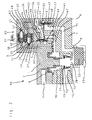
- FIG. 1 is a cross-sectional view of a valve arrangement consisting of an operating valve arrangement and a control valve arrangement in accordance with an embodiment of the invention in which the control valve arrangement is located laterally of the operating valve arrangement on the lower part of the housing;
- FIG. 2 is a cross-sectional view of a valve arrangement in accordance with another embodiment of the invention substantially identical to the valve arrangement shown in FIG. 1, in which the control valve arrangement is provided in the form of a lid located laterally of the operating valve arrangement on the upper part of the housing.
- a valve arrangement in accordance with an embodiment of the invention includes an operating valve arrangement 66 and a control valve arrangement 65 combined into one component.
- the operating valve arrangement 66 is provided in the form of a relay valve in which a piston serving as a relay piston 2 is movably installed in a housing 4 , 1 comprised of a lower housing part 4 and an upper housing part 1 .
- a piston serving as a relay piston 2 is movably installed in a housing 4 , 1 comprised of a lower housing part 4 and an upper housing part 1 .
- One side of the relay piston 2 forms the boundary of a control chamber 6 , and the other side thereof, located away from the control chamber 6 , similarly delimits a pressure medium output chamber 10 .
- the pressure medium output chamber 10 can be selectively connected via an inlet and outlet valve arrangement 13 , 12 , 11 to a pressure medium input chamber 16 or a pressure medium outlet 20 of the housing 4 , 1 , or can be closed off from both.
- the inlet valve 13 , 12 of the inlet and outlet valve arrangement 13 , 12 , 11 is comprised of a ring-shaped inlet seat 13 and a valve closing element 12 which is movable relative thereto.
- the valve closing element 12 is biased against the inlet seat 13 , by a spring 18 .
- the outlet valve 11 , 12 is formed by the free end of a tubular extension of the relay piston 2 configured as an output seat 11 , and the valve closing element 12 .
- the end of the pressure medium outlet 20 lets out into a chamber 8 in which noise-suppressing means 22 are provided.
- the wall surrounding the above-mentioned chamber 8 is provided with passage openings 23 for the pressure medium.
- the chamber 8 , and the noise-suppressing means 22 which may be made of a knit plastic material, constitute components of a noise suppressor which is preferably connected in a removable manner to the housing 4 , 1 .
- the control chamber 6 is connected to a control input 7 of the housing 4 , 1 , which, in turn, can be selectively connected to a source of control pressure or to a pressure medium sink via a valve (not shown), in the form of, for example, a motor vehicle braking valve.
- the pressure medium input chamber 16 is connected to a pressure medium input 15 of the housing 4 , 1 , which, in turn, is connected to a source of pressure medium.
- a pressure medium output 9 of the housing 4 , 1 is connected to the pressure medium output chamber 10 .
- the control valve arrangement 65 includes a housing 63 which is laterally attached to the lower housing part 4 of the operating valve arrangement 66 by means of suitable fasteners, for example, screws.
- the housing 63 of the control valve arrangement 5 is provided with a pressure medium input chamber 59 , a pressure medium output chamber 57 and a pressure medium outlet 21 .
- the pressure medium input chamber 59 is connected to a pressure medium input 64 of the housing 63 .
- the control valve arrangement 65 and the operating valve arrangement 66 are positioned relative to one another in such a manner that the pressure medium input 64 of the control valve arrangement 65 is directly aligned with the pressure medium output 9 of the operating valve arrangement 66 .
- the pressure medium output chamber 57 is connected to a pressure medium output 55 of the housing 63 .
- a consumer (not shown), provided, for example, in the form of a brake cylinder, is connected to the pressure medium output 55 via a suitable pressure medium channel.
- the pressure medium input chamber 59 and the pressure medium output chamber 57 of the control valve arrangement 65 can be selectively connected to each other or closed off from one another via a first controlled valve serving as an inlet valve 58 , 56 .
- a first control piston 53 is provided to permit actuation of the inlet valve 58 , 56 .
- the first control piston 53 is formed by a membrane, an outer edge of which is disposed between facing sides presented by an area portion 61 of the operating valve arrangement 66 and an area portion 60 of the control valve arrangement 65 , and is held in place, for example, by clamped engagement between these two area portions 61 and 60 .
- the area portions 51 and 60 thus serve as seats for the first control piston 53 .
- the inlet valve 58 , 56 is comprised of an inlet seat 58 which is integral to the housing and a valve closing element 56 which is formed by a reinforced area of the membrane.
- the valve closing element 56 is biased against the inlet seat 58 by a spring 54 .
- One end of the spring 54 is supported by the housing 4 , 1 of the operating valve arrangement 66 , and an opposite end thereof biases the valve closing element 56 in the direction of the inlet seat 58 .
- the pressure medium output chamber 57 of the control valve arrangement 65 can be selectively connected to or closed off from the pressure medium outlet 21 of the control valve arrangement 65 via a second controlled valve serving as an outlet valve 52 , 51 .
- the pressure medium outlet 21 of the control valve arrangement 65 lets out into a pressure medium channel 19 provided in the form of a housing channel located in the housing 4 , 1 of the operating valve arrangement 66 .
- the end of the pressure medium channel 19 distant from the pressure medium outlet 21 of the control valve arrangement 65 in turn lets out into the pressure medium outlet 20 of the operating valve arrangement 66 .
- the pressure medium outlet 21 of the control valve arrangement 65 is connected directly to the pressure medium outlet 20 of the operating valve arrangement 66 , rather than being connected to the pressure medium outlet 20 via the pressure medium output chamber 10 of the operating valve arrangement 66 .
- a common pressure medium outlet provided in the valve arrangement 66 , 65 is alone sufficient to permit a venting of the consumer in a manner independent of a venting of the pressure medium output chamber 10 of the operating valve arrangement 66 .
- the inlet valve 58 , 56 and the outlet valve 52 , 51 together form a controlled valve arrangement 58 , 56 , 52 , 51 by means of which the pressure medium output chamber 57 of the control valve arrangement 65 can be selectively connected, as mentioned above, to the pressure medium input chamber 59 or to the pressure medium outlet 21 of the control valve arrangement 65 .
- a second control piston 49 permits actuation of the outlet valve 52 , 51 .
- the second control piston 49 is also formed by a membrane, an outer edge of which is attached in a seat of the control piston 49 located in the housing 63 of the control valve arrangement 65 .
- the outlet valve 52 , 51 comprises an outlet seat 52 integral with the housing 63 , and a closing element 51 which is formed by a reinforced area of the membrane. The closing element 51 is held in biased contact against the outlet seat 52 by a spring 50 .
- One side of the first control piston 53 delimits the pressure medium input chamber 59 located in the housing 63 of the control valve arrangement 65 , and the other side of the first control piston bounds a first control chamber 62 , located within the housing 4 , 1 of the operating valve arrangement 66 or constituted by a recess in the wall of the housing 4 , 1 of the operating valve arrangement 66 .
- the recess constituting the first control chamber 62 is located in the side of the wall of the housing 4 , 1 adjoining the control valve arrangement 65 .
- One side of the second control piston 49 delimits the pressure medium output chamber 57 , and the other side bounds a second control chamber 48 of the control valve arrangement 65 located in the housing 63 of the control valve arrangement 65 .
- the first control chamber 62 is connected to a pressure medium output 27 of a first solenoid valve 28 , 29 , 34 , 35 via a pressure medium channel 5 located in the housing 4 , 1 of the operating valve arrangement 66 and provided in the form of a housing channel.
- the first solenoid valve 28 , 29 , 34 , 35 which is in the form of a 3/2 way valve, is provided with an inlet valve 28 , 29 and an outlet valve 34 , 35 .
- a pressure medium input 26 of the first solenoid valve 28 , 29 , 34 , 35 is constituted by a pressure medium channel provided in the form of a housing channel located in the housing 4 , 1 of the operating valve arrangement 66 .
- the pressure medium input 26 is followed by an additional pressure medium channel 24 located in the housing 4 , 1 of the operating valve arrangement 66 , and which is also provided in the form of a housing channel, which connects the pressure medium input 26 directly to the pressure medium output chamber 10 of the operating valve arrangement 66 .
- the inlet valve 28 , 29 has an inlet seat 28 and a valve closing element 29 , wherein the inlet seat 28 is formed by a ring-shaped projection of the housing 4 , 1 of the operating valve arrangement 66 surrounding the pressure medium input 26 on a side thereof directed towards the valve closing element 29
- the valve closing element 29 of the inlet valve 28 , 29 is biased by the force of a spring 30 against the inlet seat 28 .
- the outlet valve 34 , 35 comprises an outlet seat 34 and a valve closing element 35 .
- the valve closing elements 29 and 35 are constituted by the ends of an armature 32 which acts together with a coil 33 .
- a pressure medium outlet 36 of the first solenoid valve 28 , 29 , 34 , 35 is connected to the pressure medium outlet 21 of the control valve arrangement 65 via a pressure medium channel 45 , provided in the form of a housing channel located in the housing 63 of the control valve arrangement 65 .
- the first solenoid valve 28 , 29 , 34 , 35 permits selective connection of the first control chamber 62 of the control valve arrangement 65 to the pressure medium output chamber 10 of the operating valve arrangement 66 or to the pressure medium outlet 21 of the control valve arrangement 65 .
- the inlet seat 28 , the pressure medium output 27 and the spring 30 of the first solenoid valve 28 , 29 , 34 , 35 are located in a recess 3 of the housing 4 , 1 of the operating valve arrangement 66 , said recess 3 being located in the side of the wall of the housing 4 , 1 of the operating valve arrangement 66 adjoining the housing 63 of the control valve arrangement 65 .
- the coil 33 and the outlet seat 34 of the first solenoid valve 28 , 29 , 34 , 35 are located in a recess 37 in the housing 63 adjoining the housing 4 , 1 of the operating valve arrangement 66 .
- a second solenoid valve 38 , 39 , 42 , 41 is located in the recess 37 of the housing 63 of the control valve arrangement 65 , which is also designed as a 3/2 way valve and including an inlet valve 38 , 39 and an outlet valve 42 , 41 .
- the second solenoid valve 38 , 39 , 42 , 41 permits the selective connection of the second control chamber 48 of the control valve arrangement 65 to the pressure medium output chamber 10 of the operating valve arrangement 66 or to the pressure medium outlet 21 of the control valve arrangement 65 .
- the second solenoid valve 38 , 39 , 42 , 41 is provided with a inlet valve 38 , 39 comprising an inlet seat 38 and a valve closing element 39 , and with an outlet valve 42 , 41 comprising an outlet seat 42 and a valve closing element 41 .
- the valve closing element 41 of the outlet valve 42 , 41 is biased against the outlet seat 42 by the force of a spring 43 .
- the valve closing elements 39 and 41 are formed by the ends of an armature 47 which acts together with a coil 46 .
- a pressure medium input 25 of the second solenoid valve 38 , 39 , 42 , 41 is connected to the pressure medium channel 24 located in the housing 4 , 1 of the operating valve arrangement 66 via a pressure medium channel provided in the form of a housing channel located in the housing 4 , 1 of the operating valve arrangement 66 .
- the pressure medium input 25 of the second solenoid valve 38 , 39 , 42 , 41 is thus also directly connected to the pressure medium output chamber 10 of the operating valve arrangement 66 .
- a pressure medium output of the second solenoid valve 38 , 39 , 42 , 41 is connected to the second control chamber 48 via a pressure medium channel 44 provided in the form of a housing channel.
- a pressure medium outlet 40 of the second solenoid valve 38 , 39 , 42 , 41 is connected to the pressure medium outlet 21 of the control valve arrangement 65 via the pressure medium channel 45 .
- Sealing rings are installed between the sides of the operating valve arrangement 66 facing each other and the control valve arrangement 65 in such manner that they enclose, in the manner of an o-ring seal, the transitional zones from the pressure medium channels of the operating valve arrangement 66 to the pressure medium channels of the control valve arrangement 65 .
- the operating valve arrangement 66 When control pressure is fed into the control chamber 6 of the operating valve arrangement 66 , the operating valve arrangement 66 delivers a pressure which is dependent upon the level of the control pressure. The delivered pressure opens the inlet valve 58 , 56 of the control valve arrangement 65 . The delivered pressure then travels through the control valve arrangement 65 and out of the pressure medium output 55 of the control valve arrangement 65 to the consumer. During this process, the output pressure of the operating valve arrangement 66 flows through the open inlet valve 38 , 39 of the second solenoid valve 38 , 39 , 42 , 41 and into the second control chamber 48 of the control valve arrangement 65 , thereby maintaining the outlet valve 52 , 51 in its closed position.
- the first solenoid valve 28 , 29 , 34 , 35 is actuated in such manner that the outlet valve 34 , 35 thereof is moved into a closed position and the inlet valve 28 , 29 thereof into an open position.
- the compressed air then flows into the first control chamber 62 assigned to the inlet valve 58 , 56 of the control valve arrangement 65 via the first solenoid valve 28 , 29 , 34 , 35 .
- the inlet valve 58 , 56 is resultantly moved to a closed position.
- the solenoid valve 38 , 39 , 42 , 41 assigned to the second control chamber 48 of the control valve arrangement 67 is actuated in such manner that the inlet valve 38 , 39 thereof closes and the outlet valve 42 , 41 thereof opens.
- the second control chamber 48 is then vented via the pressure medium outlet 21 of the control valve arrangement 65 and the pressure medium outlet 20 of the operating valve arrangement 66 in communication therewith.
- the pressure in the consumer is lowered via the outlet valve 52 , 51 of the control valve arrangement 65 which is then moved to its open position and via the pressure medium outlet 21 of the control valve arrangement 65 and the pressure medium outlet 20 of the operating valve arrangement 66 .
- the first solenoid valve 28 , 29 , 34 , 35 is also actuated in such manner that the inlet valve 28 , 29 thereof is moved into its closed position and the outlet valve 34 , 35 thereof into its open position.
- the first control chamber 62 assigned to inlet valve 58 , 56 of the control valve arrangement 65 is vented via the pressure medium outlet 21 of the control valve arrangement 65 and the pressure medium outlet 20 of the operating valve arrangement 66 .
- the pressure in the consumer is then lowered via the inlet valve 58 , 56 of the control valve arrangement 65 which is moved into its open position and via the pressure medium output chamber 10 and the pressure medium outlet 20 of the operating valve arrangement 66 .
- FIG. 2 a valve arrangement is depicted which comprises an operating valve arrangement and a control valve arrangement, and which employs essentially the same design as the valve arrangement shown in FIG. 1 .
- the control valve arrangement is not located laterally on the lower housing part 4 , but rather, is provided laterally, in the form of a lid, on the upper housing part 1 of the operating valve arrangement 66 .
- the disclosure given below is essentially directed only to the differences in arrangement of the control valve arrangement on the operating valve arrangement from that of the valve arrangement according to FIG. 1, and to the partially modified arrangement of the housing channels serving as pressure medium channels.
- the components which are identical to the components shown in FIG. 1 are given the same reference numbers.
- the housing 4 , 1 of the operating valve arrangement 66 comprises a lower housing part 4 and an upper housing part 1 serving as a lid of the housing 4 , 1 .
- the control valve arrangement 65 is installed on one side of the upper housing part 1 .
- the control valve arrangement 65 is connected to the operating valve arrangement 66 by means of suitable fasteners, for example, screws.
- the lower housing part 4 and the upper housing part 1 are designed so that they define the boundary of a step-shaped recess which serves as a seat for the control valve arrangement 65 .
- the first control piston 53 of the inlet valve 58 , 56 of the control valve arrangement 65 is formed by a membrane, an outer edge of which is installed between the sides facing each other of an area portion 61 of the upper housing part 1 of the operating valve arrangement 66 and of an area portion 60 of the control valve arrangement 65 , and which is held in place by clamped engagement between these area portions 61 and 60 .
- the inlet seat 28 of the first solenoid valve 28 , 29 , 34 , 35 is formed by a ring-shaped extension of the upper housing part 1 of the operating valve arrangement 66 which surrounds the pressure medium input 26 on a side thereof directed towards the valve closing element 29 .
- the pressure medium input 26 of the first solenoid valve 28 , 29 , 34 , 35 and the pressure medium input 25 of the second solenoid valve 38 , 39 , 32 , 41 are connected via a common pressure medium channel 17 to the pressure medium output 9 of the operating valve arrangement 66 .
- the pressure medium input 64 of the control valve arrangement 65 is connected to the pressure medium output 9 of the operating valve arrangement 66 and the pressure medium outlet 21 of the control valve arrangement 65 is connected via a channel-pressure medium channel 14 directly to the chamber 8 assigned to the pressure medium outlet 20 of the operating valve arrangement 66 .
- the above-mentioned pressure medium channel 17 is formed by a housing channel provided in the upper housing part 1 and the channel-pressure medium channel 14 is formed by a housing channel of the operating valve arrangement 66 located in the lower housing part 4 .
- the passages from the pressure medium channels of the operating valve arrangement 66 to the pressure medium channels of the control valve arrangement 65 , as well as the passage from the pressure medium output 9 of the operating valve arrangement 66 to the pressure medium input 64 of the control valve arrangement 65 are provided with enclosing sealing elements, conveniently in the form of o-rings.
- the channel-pressure medium channel 14 located in the housing 4 , 1 of the operating valve arrangement 66 following the pressure medium outlet 21 of the control valve arrangement 65 lets out in the same chamber 8 in which the pressure medium outlet 20 of the operating valve arrangement 66 also lets out.
- the chamber 8 may be a chamber on the inlet side of a noise suppressor, as described with reference to the figures, or may alternatively be a chamber delimited by a connection piece for the noise suppressor of the operating valve arrangement or any other chamber included as part of the operating valve arrangement 66 connecting the pressure medium outlet 20 to the channel-pressure medium channel 14 .
- the pressure medium outlet 21 of the control valve arrangement 65 is connected to the pressure medium outlet 20 of the operating valve arrangement 66 . In all instances, only one noise suppressor is required for the operating valve arrangement 66 and for the control valve arrangement 65 .
- the solenoid valves 28 , 29 , 34 , 35 and 38 , 39 , 42 , 41 are installed in the recess 37 of the control valve arrangement 65 in such manner that the electrical contact elements of the plug-in device 31 extend essentially at a perpendicular to the upper housing part 1 of the valve arrangement 66 , 65 .
- the plug-in device 31 is thus located on the upper part of the valve arrangement 66 , 65 .
- control chamber 62 for the inlet valve 58 , 56 of the control valve arrangement 65 the pressure medium input 26 , the inlet seat 28 and the pressure medium output 27 of the first solenoid valve 28 , 29 , 34 , 35 of the control valve arrangement 65 and also the control chamber 62 of the inlet valve 58 , 56 of the control valve arrangement 65 are installed with the pressure medium channel 5 connecting the pressure medium output 27 of the first solenoid valve 28 , 29 , 34 , 35 within housing 4 , 1 of the operating valve arrangement 66 , and since, furthermore, part of the seat of the first control piston 53 is constituted by a area portion 61 of the operating valve arrangement 66 , part of the control valve arrangement 65 is located in the operating valve arrangement 66 or part of the control valve arrangement 65 is constituted by the operating valve arrangement 66 .
- the complete control valve arrangement 65 in which the above-mentioned control chamber 62 , the seat for the one control piston 53 and the above-mentioned parts of a solenoid valve 28 , 29 , 34 , 35 are located in the housing 63 of the control valve arrangement 65 , can be installed directly on the operating valve arrangement 66 or in a recess of the operating valve arrangement 66 . Also, in an embodiment of the invention designed in this manner, the pressure medium outlet 21 of the control valve arrangement 65 is connected to the pressure medium outlet 20 of the operating valve arrangement 66 .
- the recess for the control pistons 53 and 49 of the two controlled valves 58 , 56 and 52 , 51 can also be formed by area portions of the sides of the operating valve arrangement 66 and the control valve arrangement 65 which face each other.
- the pressure of the pressure medium output chamber 10 of the operating valve arrangement 66 can be used as control pressure for the two controlled valves 58 , 56 and 52 , 51 .
- valve arrangement according to the invention can be used in a pneumatic as well as in a hydraulic system, wherein the system may be a motor vehicle braking system or any other installation finctioning with a pressure medium.
Landscapes
- Engineering & Computer Science (AREA)
- Physics & Mathematics (AREA)
- Transportation (AREA)
- Mechanical Engineering (AREA)
- Electromagnetism (AREA)
- Fluid Mechanics (AREA)
- Fluid-Driven Valves (AREA)
- Magnetically Actuated Valves (AREA)
Applications Claiming Priority (2)
| Application Number | Priority Date | Filing Date | Title |
|---|---|---|---|
| DE1998147311 DE19847311A1 (de) | 1998-10-14 | 1998-10-14 | Ventileinrichtung |
| DE19847311 | 1998-10-14 |
Publications (1)
| Publication Number | Publication Date |
|---|---|
| US6659129B1 true US6659129B1 (en) | 2003-12-09 |
Family
ID=7884414
Family Applications (1)
| Application Number | Title | Priority Date | Filing Date |
|---|---|---|---|
| US10/252,613 Expired - Lifetime US6659129B1 (en) | 1998-10-14 | 1999-10-06 | Valve arrangement |
Country Status (3)
| Country | Link |
|---|---|
| US (1) | US6659129B1 (fr) |
| EP (1) | EP0994003B1 (fr) |
| DE (2) | DE19847311A1 (fr) |
Cited By (7)
| Publication number | Priority date | Publication date | Assignee | Title |
|---|---|---|---|---|
| US20050167351A1 (en) * | 2004-01-29 | 2005-08-04 | Herman Peter K. | Liquid additive slow-release apparatus driven by a filter pressure gradient |
| US20060180537A1 (en) * | 2004-01-29 | 2006-08-17 | Loftis Ted S | Pressure gradient dosing system for fluid supply |
| US20120181852A1 (en) * | 2009-06-29 | 2012-07-19 | Jan Grebe | Pressure control valve arrangement having pressure medium guiding surface integrally formed onto a projection of the cover |
| US20130214588A1 (en) * | 2010-11-05 | 2013-08-22 | Wabco Gmbh | Valve Device, Brake System and Vehicle |
| US9637104B2 (en) | 2013-09-24 | 2017-05-02 | Wabco Gmbh | Valve apparatus |
| US10112590B2 (en) | 2014-08-27 | 2018-10-30 | Wabco Gmbh | Valve unit for modulating pressure in an air-brake system |
| US20190193706A1 (en) * | 2016-09-05 | 2019-06-27 | Knorr-Bremse Systeme Fuer Nutzfahrzeuge Gmbh | Solenoid valve assembly for a braking system for a vehicle, braking system for a vehicle, and method for mounting a solenoid valve assembly for a braking system for a vehicle |
Families Citing this family (3)
| Publication number | Priority date | Publication date | Assignee | Title |
|---|---|---|---|---|
| US6267135B1 (en) * | 2000-05-03 | 2001-07-31 | Honeywell Commerical Vehicle Systems Co. | ABS modulator with damping foam on exhaust diaphragm |
| CN107600059B (zh) * | 2017-10-11 | 2024-01-12 | 浙江万安科技股份有限公司 | 集成式继动阀带abs电磁阀总成 |
| DE102018127822A1 (de) * | 2018-11-07 | 2020-05-07 | Knorr-Bremse Systeme für Nutzfahrzeuge GmbH | Ventilanordnung und ein Verfahren zur Drucksteuerung |
Citations (11)
| Publication number | Priority date | Publication date | Assignee | Title |
|---|---|---|---|---|
| DE498584C (de) | 1926-08-29 | 1930-05-23 | Max Schaidhauf Dr Ing | Verfahren zur Herstellung von Kunstgraphit |
| DE2601311A1 (de) | 1976-01-15 | 1977-07-21 | Knorr Bremse Gmbh | Pneumatisches relaisventil |
| DE3931761A1 (de) | 1989-09-22 | 1991-04-04 | Knorr Bremse Ag | Elektro-pneumatisches regelventil mit relaisfunktion |
| WO1991006456A1 (fr) | 1989-11-04 | 1991-05-16 | Grau Limited | Circuits de freinage de vehicule |
| DE4038575A1 (de) | 1989-12-22 | 1991-06-27 | Bosch Gmbh Robert | Drucksteuerventil fuer druckluftbetaetigte fahrzeugbremsanlagen |
| WO1991008934A1 (fr) | 1989-12-12 | 1991-06-27 | Grau Limited | Systemes de freinage de vehicules |
| DE4005608A1 (de) | 1990-02-22 | 1991-09-05 | Bosch Gmbh Robert | Drucksteuerventilaggregat, insbesondere fuer druckluftbetaetigte fahrzeugbremsanlagen |
| EP0547407A1 (fr) | 1991-12-19 | 1993-06-23 | Robert Bosch Gmbh | Système de freinage à air comprimé, en particulier pour véhicules commerciales |
| DE4232586A1 (de) | 1992-09-23 | 1994-03-24 | Mannesmann Ag | Relaisventil für fluidische Medien |
| US5443306A (en) * | 1992-07-22 | 1995-08-22 | Grau Limited | Electrohydraulic brake control system |
| JPH0858546A (ja) | 1994-08-23 | 1996-03-05 | Jidosha Kiki Co Ltd | アンチスキッドブレーキ制御システム |
Family Cites Families (1)
| Publication number | Priority date | Publication date | Assignee | Title |
|---|---|---|---|---|
| GB9102313D0 (en) * | 1991-02-02 | 1991-03-20 | Bendix Ltd | Fluid pressure modulator valve device |
-
1998
- 1998-10-14 DE DE1998147311 patent/DE19847311A1/de not_active Withdrawn
-
1999
- 1999-07-15 DE DE59904930T patent/DE59904930D1/de not_active Expired - Lifetime
- 1999-07-15 EP EP19990113811 patent/EP0994003B1/fr not_active Expired - Lifetime
- 1999-10-06 US US10/252,613 patent/US6659129B1/en not_active Expired - Lifetime
Patent Citations (11)
| Publication number | Priority date | Publication date | Assignee | Title |
|---|---|---|---|---|
| DE498584C (de) | 1926-08-29 | 1930-05-23 | Max Schaidhauf Dr Ing | Verfahren zur Herstellung von Kunstgraphit |
| DE2601311A1 (de) | 1976-01-15 | 1977-07-21 | Knorr Bremse Gmbh | Pneumatisches relaisventil |
| DE3931761A1 (de) | 1989-09-22 | 1991-04-04 | Knorr Bremse Ag | Elektro-pneumatisches regelventil mit relaisfunktion |
| WO1991006456A1 (fr) | 1989-11-04 | 1991-05-16 | Grau Limited | Circuits de freinage de vehicule |
| WO1991008934A1 (fr) | 1989-12-12 | 1991-06-27 | Grau Limited | Systemes de freinage de vehicules |
| DE4038575A1 (de) | 1989-12-22 | 1991-06-27 | Bosch Gmbh Robert | Drucksteuerventil fuer druckluftbetaetigte fahrzeugbremsanlagen |
| DE4005608A1 (de) | 1990-02-22 | 1991-09-05 | Bosch Gmbh Robert | Drucksteuerventilaggregat, insbesondere fuer druckluftbetaetigte fahrzeugbremsanlagen |
| EP0547407A1 (fr) | 1991-12-19 | 1993-06-23 | Robert Bosch Gmbh | Système de freinage à air comprimé, en particulier pour véhicules commerciales |
| US5443306A (en) * | 1992-07-22 | 1995-08-22 | Grau Limited | Electrohydraulic brake control system |
| DE4232586A1 (de) | 1992-09-23 | 1994-03-24 | Mannesmann Ag | Relaisventil für fluidische Medien |
| JPH0858546A (ja) | 1994-08-23 | 1996-03-05 | Jidosha Kiki Co Ltd | アンチスキッドブレーキ制御システム |
Non-Patent Citations (2)
| Title |
|---|
| WABCO Brochure, ABS Valve Package-Part No. Identification 472 500 100.0, pp. 1 and 8-11 (1997). |
| WABCO Brochure, ABS Valve Package—Part No. Identification 472 500 100.0, pp. 1 and 8-11 (1997). |
Cited By (14)
| Publication number | Priority date | Publication date | Assignee | Title |
|---|---|---|---|---|
| US20050167351A1 (en) * | 2004-01-29 | 2005-08-04 | Herman Peter K. | Liquid additive slow-release apparatus driven by a filter pressure gradient |
| US20060180537A1 (en) * | 2004-01-29 | 2006-08-17 | Loftis Ted S | Pressure gradient dosing system for fluid supply |
| US7153422B2 (en) * | 2004-01-29 | 2006-12-26 | Fleetguard, Inc. | Liquid additive slow-release apparatus driven by a filter pressure gradient |
| US7297256B2 (en) | 2004-01-29 | 2007-11-20 | Fleet Guard, Inc. | Pressure gradient dosing system for fluid supply |
| US9039103B2 (en) * | 2009-06-29 | 2015-05-26 | Knorr-Bremse Systeme Fuer Nutzfahrzeuge Gmbh | Pressure control valve arrangement having pressure medium guiding surface integrally formed onto a projection of the cover |
| US20120181852A1 (en) * | 2009-06-29 | 2012-07-19 | Jan Grebe | Pressure control valve arrangement having pressure medium guiding surface integrally formed onto a projection of the cover |
| US20130214588A1 (en) * | 2010-11-05 | 2013-08-22 | Wabco Gmbh | Valve Device, Brake System and Vehicle |
| US9676378B2 (en) * | 2010-11-05 | 2017-06-13 | Wabco Gmbh | Valve device adaptable for brake control of a variety of pressure medium-operated vehicle brake systems |
| US9637104B2 (en) | 2013-09-24 | 2017-05-02 | Wabco Gmbh | Valve apparatus |
| US10112590B2 (en) | 2014-08-27 | 2018-10-30 | Wabco Gmbh | Valve unit for modulating pressure in an air-brake system |
| US20190193706A1 (en) * | 2016-09-05 | 2019-06-27 | Knorr-Bremse Systeme Fuer Nutzfahrzeuge Gmbh | Solenoid valve assembly for a braking system for a vehicle, braking system for a vehicle, and method for mounting a solenoid valve assembly for a braking system for a vehicle |
| CN110023158A (zh) * | 2016-09-05 | 2019-07-16 | 克诺尔商用车制动系统有限公司 | 用于车辆制动系统的电磁阀装置、车辆制动系统和用于车辆制动系统的电磁阀装置的安装方法 |
| US10988126B2 (en) * | 2016-09-05 | 2021-04-27 | Knorr-Bremse Systeme Fuer Nutzfahrzeuge Gmbh | Solenoid valve assembly for a braking system for a vehicle, braking system for a vehicle, and method for mounting a solenoid valve assembly for a braking system for a vehicle |
| CN110023158B (zh) * | 2016-09-05 | 2021-08-24 | 克诺尔商用车制动系统有限公司 | 用于车辆制动系统的电磁阀装置、车辆制动系统和用于车辆制动系统的电磁阀装置的安装方法 |
Also Published As
| Publication number | Publication date |
|---|---|
| EP0994003A3 (fr) | 2001-05-30 |
| DE59904930D1 (de) | 2003-05-15 |
| DE19847311A1 (de) | 2000-04-20 |
| EP0994003B1 (fr) | 2003-04-09 |
| EP0994003A2 (fr) | 2000-04-19 |
Similar Documents
| Publication | Publication Date | Title |
|---|---|---|
| US6659129B1 (en) | Valve arrangement | |
| US5335983A (en) | Hydraulic regulator for a brake pressure control apparatus | |
| JPH02190687A (ja) | パイロット制御される方向切換弁 | |
| KR19980081034A (ko) | 베이스 부착형 변환밸브에 부착하기 위한 압력조절밸브 | |
| JP2009539668A (ja) | 人力式の常用ブレーキ及びホイールスリップを制御するための装置を備えた液圧式の車両ブレーキ装置 | |
| US7052095B2 (en) | Electropneumatic control valve with a back-up valve | |
| US6966341B2 (en) | Compressed air control apparatus for compressed air systems of motor vehicles | |
| US6792971B2 (en) | Pilot control valve having a pressure compensation | |
| US9637104B2 (en) | Valve apparatus | |
| US6405755B1 (en) | Directly controlled magnetic valve | |
| JPH11236904A (ja) | 空気力式制御弁 | |
| HUT56777A (en) | Pressure controlling valve unit particularly for the pneumatic brake assemblies of motor vehicles | |
| KR100553657B1 (ko) | 전자석 밸브 장치 | |
| US6227627B1 (en) | Hydraulic motor vehicle braking system with wheel slip control | |
| US5154203A (en) | Proportional modulator for an electropneumatic braking system | |
| US4915458A (en) | Relay valve apparatus | |
| US7007713B2 (en) | Pressure control apparatus | |
| AU2002316881A1 (en) | Electropneumatic control valve with a seal arrangement | |
| US4425940A (en) | Pressure control system | |
| US5328253A (en) | Electropneumatic control system for compressed air brakes of rail cars | |
| JPH05231558A (ja) | バルブユニット | |
| GB2268574A (en) | Exhaust valves | |
| WO1992016400A1 (fr) | Procede et appareil de commande du niveau de pression dans un systeme de freinage adaptatif a air comprime | |
| EP0516348B1 (fr) | Valve modulatrice pour fluide de pression | |
| JPH11304037A (ja) | バルブ |
Legal Events
| Date | Code | Title | Description |
|---|---|---|---|
| AS | Assignment |
Owner name: WABCO GMBH, GERMANY Free format text: ASSIGNMENT OF ASSIGNORS INTEREST;ASSIGNORS:KIEL, BERND;KORPAK, GEORG;MENZE, WILFRIED;REEL/FRAME:010366/0680 Effective date: 19991021 |
|
| AS | Assignment |
Owner name: WABCO GMBH, GERMANY Free format text: ASSIGNMENT OF ASSIGNORS INTEREST;ASSIGNORS:KIEL, BERND;KORPACK, GEORG;MENZE, WILFRIED;REEL/FRAME:014328/0265 Effective date: 19991021 |
|
| STCF | Information on status: patent grant |
Free format text: PATENTED CASE |
|
| FPAY | Fee payment |
Year of fee payment: 4 |
|
| FEPP | Fee payment procedure |
Free format text: PAYOR NUMBER ASSIGNED (ORIGINAL EVENT CODE: ASPN); ENTITY STATUS OF PATENT OWNER: LARGE ENTITY |
|
| FPAY | Fee payment |
Year of fee payment: 8 |
|
| FPAY | Fee payment |
Year of fee payment: 12 |