US6650776B2 - Two-dimensional code recognition processing method, two-dimensional code recognition processing apparatus, and storage medium - Google Patents
Two-dimensional code recognition processing method, two-dimensional code recognition processing apparatus, and storage medium Download PDFInfo
- Publication number
- US6650776B2 US6650776B2 US09/340,932 US34093299A US6650776B2 US 6650776 B2 US6650776 B2 US 6650776B2 US 34093299 A US34093299 A US 34093299A US 6650776 B2 US6650776 B2 US 6650776B2
- Authority
- US
- United States
- Prior art keywords
- binary data
- dimensional code
- code
- detecting
- reference cell
- Prior art date
- Legal status (The legal status is an assumption and is not a legal conclusion. Google has not performed a legal analysis and makes no representation as to the accuracy of the status listed.)
- Expired - Lifetime
Links
- 238000003672 processing method Methods 0.000 title claims abstract description 20
- 238000012545 processing Methods 0.000 title claims description 20
- 238000000034 method Methods 0.000 claims abstract description 47
- 238000001514 detection method Methods 0.000 claims description 15
- 230000008569 process Effects 0.000 description 40
- 230000006870 function Effects 0.000 description 13
- 230000014509 gene expression Effects 0.000 description 13
- 230000015654 memory Effects 0.000 description 6
- 238000004891 communication Methods 0.000 description 5
- 238000013524 data verification Methods 0.000 description 5
- 230000000717 retained effect Effects 0.000 description 3
- PXFBZOLANLWPMH-UHFFFAOYSA-N 16-Epiaffinine Natural products C1C(C2=CC=CC=C2N2)=C2C(=O)CC2C(=CC)CN(C)C1C2CO PXFBZOLANLWPMH-UHFFFAOYSA-N 0.000 description 1
- 238000004590 computer program Methods 0.000 description 1
- 238000010586 diagram Methods 0.000 description 1
- 230000000694 effects Effects 0.000 description 1
- 238000005286 illumination Methods 0.000 description 1
- 239000004973 liquid crystal related substance Substances 0.000 description 1
- 230000003287 optical effect Effects 0.000 description 1
- 230000002093 peripheral effect Effects 0.000 description 1
- 239000004065 semiconductor Substances 0.000 description 1
- 230000005236 sound signal Effects 0.000 description 1
- 230000009466 transformation Effects 0.000 description 1
Images


Classifications
-
- G—PHYSICS
- G06—COMPUTING; CALCULATING OR COUNTING
- G06K—GRAPHICAL DATA READING; PRESENTATION OF DATA; RECORD CARRIERS; HANDLING RECORD CARRIERS
- G06K7/00—Methods or arrangements for sensing record carriers, e.g. for reading patterns
- G06K7/10—Methods or arrangements for sensing record carriers, e.g. for reading patterns by electromagnetic radiation, e.g. optical sensing; by corpuscular radiation
- G06K7/14—Methods or arrangements for sensing record carriers, e.g. for reading patterns by electromagnetic radiation, e.g. optical sensing; by corpuscular radiation using light without selection of wavelength, e.g. sensing reflected white light
-
- G—PHYSICS
- G06—COMPUTING; CALCULATING OR COUNTING
- G06K—GRAPHICAL DATA READING; PRESENTATION OF DATA; RECORD CARRIERS; HANDLING RECORD CARRIERS
- G06K7/00—Methods or arrangements for sensing record carriers, e.g. for reading patterns
- G06K7/10—Methods or arrangements for sensing record carriers, e.g. for reading patterns by electromagnetic radiation, e.g. optical sensing; by corpuscular radiation
-
- G—PHYSICS
- G06—COMPUTING; CALCULATING OR COUNTING
- G06K—GRAPHICAL DATA READING; PRESENTATION OF DATA; RECORD CARRIERS; HANDLING RECORD CARRIERS
- G06K19/00—Record carriers for use with machines and with at least a part designed to carry digital markings
- G06K19/06—Record carriers for use with machines and with at least a part designed to carry digital markings characterised by the kind of the digital marking, e.g. shape, nature, code
- G06K19/06009—Record carriers for use with machines and with at least a part designed to carry digital markings characterised by the kind of the digital marking, e.g. shape, nature, code with optically detectable marking
- G06K19/06037—Record carriers for use with machines and with at least a part designed to carry digital markings characterised by the kind of the digital marking, e.g. shape, nature, code with optically detectable marking multi-dimensional coding
-
- G—PHYSICS
- G06—COMPUTING; CALCULATING OR COUNTING
- G06K—GRAPHICAL DATA READING; PRESENTATION OF DATA; RECORD CARRIERS; HANDLING RECORD CARRIERS
- G06K19/00—Record carriers for use with machines and with at least a part designed to carry digital markings
- G06K19/06—Record carriers for use with machines and with at least a part designed to carry digital markings characterised by the kind of the digital marking, e.g. shape, nature, code
- G06K19/06009—Record carriers for use with machines and with at least a part designed to carry digital markings characterised by the kind of the digital marking, e.g. shape, nature, code with optically detectable marking
- G06K19/06046—Constructional details
- G06K19/06131—Constructional details the marking comprising a target pattern, e.g. for indicating the center of the bar code or for helping a bar code reader to properly orient the scanner or to retrieve the bar code inside of an image
-
- G—PHYSICS
- G06—COMPUTING; CALCULATING OR COUNTING
- G06K—GRAPHICAL DATA READING; PRESENTATION OF DATA; RECORD CARRIERS; HANDLING RECORD CARRIERS
- G06K7/00—Methods or arrangements for sensing record carriers, e.g. for reading patterns
- G06K7/10—Methods or arrangements for sensing record carriers, e.g. for reading patterns by electromagnetic radiation, e.g. optical sensing; by corpuscular radiation
- G06K7/14—Methods or arrangements for sensing record carriers, e.g. for reading patterns by electromagnetic radiation, e.g. optical sensing; by corpuscular radiation using light without selection of wavelength, e.g. sensing reflected white light
- G06K7/1404—Methods for optical code recognition
- G06K7/1408—Methods for optical code recognition the method being specifically adapted for the type of code
- G06K7/1417—2D bar codes
-
- G—PHYSICS
- G06—COMPUTING; CALCULATING OR COUNTING
- G06K—GRAPHICAL DATA READING; PRESENTATION OF DATA; RECORD CARRIERS; HANDLING RECORD CARRIERS
- G06K7/00—Methods or arrangements for sensing record carriers, e.g. for reading patterns
- G06K7/10—Methods or arrangements for sensing record carriers, e.g. for reading patterns by electromagnetic radiation, e.g. optical sensing; by corpuscular radiation
- G06K7/14—Methods or arrangements for sensing record carriers, e.g. for reading patterns by electromagnetic radiation, e.g. optical sensing; by corpuscular radiation using light without selection of wavelength, e.g. sensing reflected white light
- G06K7/1404—Methods for optical code recognition
- G06K7/1439—Methods for optical code recognition including a method step for retrieval of the optical code
- G06K7/1443—Methods for optical code recognition including a method step for retrieval of the optical code locating of the code in an image
Definitions
- the present invention relates to a two-dimensional code recognition processing method, a two-dimensional code recognition processing apparatus, and a storage medium for allowing a computer to execute a two-dimensional code recognition processing program. More particularly, the invention relates to a two-dimensional code recognition processing method, a two-dimensional code recognition processing apparatus, and a storage medium for allowing a computer to execute a two-dimensional code recognition processing program, the method and the apparatus providing efficient and accurate recognition of code data based on image data of a suitably captured two-dimensional code.
- bar code system is used extensively in various industrial fields.
- the system involves encoding in bars alphanumeric characters representing types and conditions of goods and articles, and typically attaching such codes to the goods and products so that the codes may be scanned later for retrieval of relevant information (e.g., about their types and conditions).
- FIG. 20 shows a so-called one-dimensional bar code.
- a bar code label 500 is made up of a code part 501 and an ID (identification number) part 502 .
- the code part 501 is a combination of different widths of bars (in black) and bar-to-bar gas (blanks).
- the ID part 502 indicates a code contained in the code part 501 .
- the ID part 502 shows as readable information alphanumeric characters that are coded in the code part 501 .
- This type of one-dimensional bar code 500 is scanned by an optical recognition apparatus called a bar code scanner for recognition.
- each code comprising a code part 601 and an ID part 602 .
- the code part 601 has a plurality of black square cells arranged two-dimensionally according to predetermined layout rules.
- the ID part 602 indicates a code that is contained in the code part 601 .
- the two-dimensional code 600 has one disadvantage. That is, when the video camera picks up an image of a two-dimensional code 600 for code recognition, it is often difficult to distinguish the code from smear, dirt or other distracting images nearby. The result is that code data are often difficult to recognize precisely.
- a two-dimensional code recognition processing method for recognizing a two-dimensional code made of a plurality of square cells arranged in accordance with predetermined layout rules, the method comprising the steps of: generating binary data from image information acquired externally in accordance with a predetermined threshold value; detecting a reference cell serving as a reference in recognizing the two-dimensional code based on the binary data generated in the binary data generating step; detecting corner cells each located in a predetermined search range with respect to the reference cell detected in the reference cell detecting step, on the basis of the binary data generated in the binary data generating step; and detecting code data assigned to the two-dimensional code existing inside an area of a code part enclosed by the reference cell and by the corner cells on the basis of the binary data generated in the binary data generating step.
- a two-dimensional code recognition processing apparatus for recognizing a two-dimensional code made of a plurality of square cells arranged in accordance with predetermined layout rules, the apparatus comprising: binary data generating means for generating binary data from image information acquired externally in accordance with a predetermined threshold value; reference cell detecting means for detecting a reference cell serving as a reference in recognizing the two-dimensional code based on the binary data generated by the binary data generating means; corner cell detecting means for detecting corner cells each located in a predetermined search range with respect to the reference cell detected by the reference cell detecting means, on the basis of the binary data generated by the binary data generating means; and code data detecting means for detecting code data assigned to the two-dimensional code existing inside an area of a code part enclosed by the reference cell and by the corner cells on the basis of the binary data generated by the binary data generating means.
- a storage medium for storing a two-dimensional code recognition processing program for recognizing a two-dimensional code made of a plurality of square cells arranged in accordance with predetermined layout rules, the program being executable by a computer and comprising the steps of: generating binary data from image information acquired externally in accordance with a predetermined threshold value; detecting a reference cell serving as a reference in recognizing the two-dimensional code based on the binary data generated in the binary data generating step; detecting corner cells each located in a predetermined search range with respect to the reference cell detected in the reference cell detecting step, on the basis of the binary data generated in the binary data generating step; and detecting code data assigned to the two-dimensional code existing inside an area of a code part enclosed by the reference cell and by the corner cells on the basis of the binary data generated in the binary data generating step.
- binary data are generated from externally acquired image information in accordance with a predetermined threshold value.
- a reference cell is detected from the binary data thus generated, the reference cell serving as a reference in recognizing a two-dimensional code.
- Corner cells are detected from within a predetermined search range with respect to the reference cell. Code data are then detected which are assigned to the two-dimensional code existing in an area of a code part enclosed by the reference cell and by the corner cells.
- FIG. 3 is another explanatory view of two-dimensional code specifications
- FIG. 4 is another explanatory view of two-dimensional code specifications
- FIGS. 5A through 5D are views depicting typical two-dimensional codes
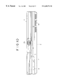
- FIG. 6 is a perspective view of a portable personal computer to which the invention is applied, with its display part swung open away from its body;
- FIG. 7 is a plan view of the computer in FIG. 1;
- FIG. 8 is a left-hand side view of the computer in FIG. 1 with its display part swung shut onto the body;
- FIG. 9 is a right-hand side view of the computer in FIG. 1 with its display part swung open 180 degrees relative to its body;
- FIG. 11 is a bottom view of the computer in FIG. 4;
- FIG. 13 is a flowchart of steps constituting a two-dimensional code recognition process
- FIG. 14 is an explanatory view indicating threshold settings
- FIG. 15 is a schematic view depicting how black pixel contiguous regions are labeled
- FIG. 16 is a flowchart of steps constituting a logo mark cell part detection process
- FIG. 17 is an explanatory view illustrating how sides AT and BT are obtained.
- FIG. 18 is a flowchart of steps constituting a code part detection process
- FIG. 20 is a schematic view of a typical one-dimensional bar code
- FIG. 21 is a schematic view of a typical two-dimensional code.
- FIG. 1 shows a personal computer 1 to which the invention is applied.
- an object 100 is illustratively a business card-like object.
- a two-dimensional code label 101 is attached (e.g., printed) onto the object 100 .
- the two-dimensional code label 101 is made of a plurality of square cells (black portions) arranged two-dimensionally in accordance with predetermined layout rules.
- Such a layout pattern of the cells represents in coded form alphanumeric characters, such as a number 200 in this example.
- the two-dimensional code label 101 comprises a logo mark part 201 and a code part 202 .
- the two parts as a whole are formed in an area consisting of seven blocks (each block represents a rectangular area of a single square cell) in the X-axis direction and 9.5 blocks in the Y-axis direction. That area is defined as the 7 ⁇ 9.5 block area, and like definition will also apply hereunder.
- the logo mark part 201 is made of a logo mark cell part 301 and a non-cell part 302 .
- the logo mark cell part 301 constitutes a 7 ⁇ 1.5 block rectangular area which, when printed, leaves blanks representing a logo mark, characters, numerals and other readable character information associated with the two-dimensional code.
- “CyberCode” attached to the two-dimensional code system forms a typical logo mark.
- Such information signifying what the two-dimensional code in question means is given in blank characters constituting a human-readable mark.
- the logo mark part 301 is not limited to expressing log marks only.
- the part may illustratively represent the name of the corporation which developed the two-dimensional code system and for which this applicant works.
- the logo mark part may also express a URL (Uniform Resource Locator) indicating where information resources are located in connection with the two-dimensional code system.
- URL is a method for uniquely designating locations where files and other information resources are stored in a distributed manner on the Internet.
- the rectangular logo mark cell part 301 indicates in a typical logo mark format what the two-dimensional code signifies as described, those who are interested in the logo mark can gain access to and grasp information about the logo mark at relevant home pages and other locations on the Internet.
- “What we call “CyberCode” is Sony's unique two-dimensional code system that offers about 16.77 million different patterns (in 24 bits). Of these patterns, about one million patterns (in 20 bits) may be registered as desired for program start-up purposes. The remaining code patterns are reserved for future service expansion. “CyberCode” works as an index to what is represented by the code in question, the index allowing relevant information to be retrieved from computer storage. When a user starts a program through a new interface feature “CyberCode Finder,” the user finds that the corresponding information leaps from the object having the “CyberCode” onto the computer screen.”
- a 7 ⁇ 1 block area on the side of the code part 202 includes the non-cell part 302 that contains no cell.
- the major axis of the logo mark cell part 301 is called a side A (in the X-axis direction in FIG. 2) and its minor axis is called a side B (in the Y-axis direction in FIG. 2 ).
- the code part 202 has a top left corner cell and a top right corner cell.
- the top left corner cell is located seven blocks above the leftmost edge of the logo mark cell part 301 ;
- the right top corner cell is seven blocks above the rightmost edge of the logo mark cell part 301 .
- a bottom left corner cell is located one block above the leftmost edge of the logo mark cell part 301
- a bottom right corner cell is one block above the rightmost edge of the logo mark cell part 301 .
- the top left, top right, bottom left and bottom right corner cells are collectively referred to as the corner cells unless they need to be distinguished specifically from one another.
- a three-block area contiguously surrounding each corner cell contains no cells.
- the corner cells are defined as the cells located as described relative to the logo mark cell part 301 , each cell having no cells in the three-block area around it.
- FIGS. 5A through 5D show typical two-dimensional codes.
- Code parts 202 of two-dimensional code labels 101 in FIG. 5A indicate code data representing ID numbers 200 , 201 , 202 , 203 , 1500 , 1501 , 1502 and 1503 in coded form.
- ID part 203 under each logo mark cell part 301 is a printed number corresponding to a coded ID number.
- each logo mark cell part 301 of the two-dimensional code label 101 has a logo mark printed as blank characters.
- FIG. 5C omits a number corresponding to the ID number in the ID part 203 of each two-dimensional code label 101 .
- each logo mark cell part 301 has a number corresponding to the ID number, printed as blank characters.
- the logo mark is printed in black in the ID part 203 .
- the code parts 202 of the two-dimensional code labels 101 in FIGS. 5A through 5D are all prepared according to the same specifications.
- the above-mentioned logo mark cell part 301 is constituted by a rectangular area having a predetermined aspect ratio and including a black pixel contiguous region made of a plurality of contiguously arranged black pixels, as will be described later.
- the logo mark cell part 301 further comprises human-readable information (as blanks) associated with the two-dimensional code.
- a rectangular logo mark cell part 301 having a predetermined aspect ratio is detected.
- the detected logo mark cell part 301 is used as a reference for detecting other cells that may exist in a predetermined search range.
- the logo mark cell part 301 is not merely provided as a readable logo mark format indication of the meaning of the two-dimensional code; the part 301 also offers a reference function for use in the two-dimensional code recognition process.
- FIGS. 6 through 11 show a typical structure of a portable personal computer 1 to which this invention is applied.
- the personal computer 1 is a mini-notebook type personal computer that primarily comprises a body 2 and a display part 3 attached swingingly to the body 2 .
- FIG. 6 is a perspective view of the computer with the display part 3 swung open away from the body 2 .
- FIG. 7 is a plan view of the computer in FIG. 6 .
- FIG. 8 is a left-hand side view of the computer with the display part 3 swung shut onto the body 2 .
- FIG. 9 is a right-hand side view of the computer with the display part 3 swung open 180 degrees relative to the body 2 .
- FIG. 10 is a front view of the computer in FIG. 8 .
- FIG. 11 is a bottom view of the computer in FIG. 9 .
- the face of the body 2 comprises a keyboard 4 and a stick type pointing device 5 .
- the keyboard 4 is used to input characters, symbols, etc.
- the stick type pointing device 5 is used to move a mouse cursor.
- a pawl 13 is provided at the upper end of the display part 3 . As shown in FIG. 8, with the display part 3 swung closed onto the body 2 , the pawl 13 hooks onto a hole 6 in the body 2 .
- a slide lever 7 furnished in a crosswise movable fashion. The slide lever 7 is used to lock and unlock the pawl 13 so that the pawl 13 is engaged with and disengaged from the hole 6 . With the pawl 13 unlocked, the display part 3 may be swung open away from the body 2 .
- Adjacent to the pawl 13 is a microphone 24 which, as depicted in FIG. 11, may pick up sound from both the front and the back side of the body 2 .
- An LCD (liquid crystal display) 21 for displaying images is provided on the front of the display part 3 .
- an image pickup part 22 mounted rotatably on the display part 3 . More specifically, the image pickup part 22 is rotatable to any position within a range of 180 degrees in the same direction as the LCD 21 and in the opposite direction thereof (i.e., toward the back).
- the image pickup part 22 is furnished with the CCD video camera 23 .
- Reference numeral 40 in FIG. 8 denotes a power switch furnished on the left-hand side of the body 2
- reference numeral 25 in FIG. 10 represents an adjusting ring used to adjust the focus of the CCD video camera 23 .
- Reference numeral 26 in FIG. 11 stands for a cover that conceals an opening through which to install an additional memory into the body 2
- reference numeral 41 denotes a hole through which to insert a pin to unlock the cover 26 .
- FIG. 12 illustrates an internal structure of the personal computer 1 .
- an internal bus 51 is connected to a CPU (central processing unit) 52 , a PC card 53 inserted as needed, a RAM (random access memory) 54 , and a graphic chip 81 .
- the internal bus 51 is coupled to an external bus 55 .
- the external bus 55 for its part, is connected to a hard disk drive (HDD) 56 , an I/O (input/output) controller 57 , a keyboard controller 58 , a stick type pointing device controller 59 , a sound chip 60 , an LCD controller 83 , and a modem 50 .
- HDD hard disk drive
- the CPU 52 is a controller that controls diverse computer functions.
- the PC card 53 is installed as needed when an optional function is to be added.
- Image data captured by the CCD video camera 23 are forwarded to a processing part 82 for processing.
- the image data processed by the processing part 82 are input to the graphic chip 81 connected to the internal bus 51 .
- the graphic chip 81 stores the input video data into an internal VRAM 81 A, and retrieves the data from the memory as needed for output to the LCD controller 83 .
- the LCD controller 83 Given the image data from the graphic chip 81 , the LCD controller 83 outputs the data to the LCD 21 for display.
- Back lights 84 are provided to illuminate the LCD 21 from the back.
- an electronic mail program (an application program) 54 A, an auto pilot program (another application program) 54 B and the OS (operating program) 54 C are transferred from the HDD 56 to the RAM 54 and retained therein.
- the electronic mail program 54 A is a program that exchanges communication messages with an external entity using a communication line such as a telephone line and by way of a network.
- a received mail acquisition function is specifically included in the electronic mail program 54 A.
- the received mail acquisition function checks a mail server 93 to see if a mail box 93 A therein contains any mail addressed to this program (i.e., to the user). If any such mail is found in the mail box 93 A, the received mail acquisition function carries out a suitable process to acquire that mail.
- the OS (operating system) 54 C controls basic computer functions.
- Typical operating systems are Windows 95 (registered trademark), Windows 98 (registered trademark) and the like.
- the two-dimensional code recognition program 56 D in operation detects a logo mark cell part 301 of a logo mark part 201 and a code part 202 , of a two-dimensional code from image data held in the VRAM 81 A of the graphic chip 81 .
- the program 56 D then recognizes code data of the code part 202 so as to retrieve relevant coded information therefrom.
- the I/O controller 57 has a microcontroller 61 equipped with an I/O interface 62 .
- the microcontroller 61 is constituted by the I/O interface 62 , a CPU 63 , a RAM 64 and a ROM 69 which are interconnected.
- the RAM 64 includes a key input status register 65 , an LED (light-emitting diode) control register 66 , a set time register 67 , and a register 68 .
- the set time register 67 is used to start the operation of a start sequence controller 76 when a time preset by the user (i.e., starting condition) is reached.
- the register 68 holds a correspondence between a preset combination of operation keys (starting condition) on the one hand and an application program to be started on the other hand.
- the corresponding application program e.g., electronic mail program
- the microcontroller 61 is connected to a backup battery 74 .
- the battery 74 allows contents of the registers 65 , 66 and 67 to be retained when power to the body 2 is turned off.
- the wake-up program 70 in the ROM 69 is a program that checks to see if a preset time in the set time register 67 is reached on the basis of time-of-day data from the RTC 75 . When the preset time is reached, the wake-up program 70 starts up a predetermined process (or program).
- the key input monitoring program 71 continuously monitors whether the PPK 9 is pushed by the user.
- the LED control program 72 controls the lighting of the message lamp ML.
- the ROM 69 contains a BIOS (basic input/output system) 73 .
- BIOS basic input/output system
- the BIOS is a software program that controls exchanges of data (input and output) between the OS or application software on the one hand and peripheral devices (e.g., display part, keyboard, hard disk drive) on the other hand.
- the sound chip 60 receives input from the microphone 24 , and supplies sound signals to the built-in speaker 8 .
- the processing part 82 When the CCD video camera 23 picks up a two-dimensional code label 101 and acquires single-frame image data therefrom, the data are processed by the processing part 82 and placed into the VRAM 81 A of the graphic chip 81 . In that state, the two-dimensional code recognition program 56 D is started from the HDD 56 .
- the CPU 52 initializes to 1 a counter “i” that counts a threshold value representing a brightness level.
- the threshold value may be set to one of five levels. More specifically, the counter setting may range in stepped fashion from a threshold value A, a maximum value corresponding to set No. 1, to a threshold value E, a minimum value corresponding to set No. 5.
- step S 2 the CPU 52 performs binarization on the image data held in the VRAM 81 A in accordance with the threshold value that is set on the counter “i”. Each pixel greater than the threshold value in brightness is coded as “0”. The “0” coded pixel is shown white when displayed. In the description that follows, each pixel whose pixel value is coded as “0” is called a white pixel.
- each pixel less than the threshold value in brightness is coded as “1”.
- the “1” coded pixel is shown black when displayed.
- each pixel whose pixel value is coded as “1” is called a black pixel.
- step S 3 as shown in FIG. 15, the CPU 52 successively numbers (labels), from top left to bottom right, regions each composed of continuous black pixels.
- step S 4 the CPU 52 obtains a total number M of black pixel contiguous regions, and checks to see if the obtained total number M is at least 257. If the value M is found to be at least 257, then the CPU 52 judges that the image frame currently stored in the VRAM 81 A is not fit for subsequent processing. In that case, step S 4 is followed by step S 5 .
- dither images Images unsuitable for subsequent processing are appreciably grainy images known as dither images. Attempts to recognize such images forcibly will overload the CPU doing the necessary computations. In such cases, recognition of the dither image is skipped and step S 5 is reached.
- the threshold value A represented by set No. 1 is the maximum threshold value in this example.
- the maximum value A is taken as the threshold for binarization, a large number of pixels constituting the image data have a brightness level relatively lower than the value A.
- the greater part of the pixels are recognized as black pixels thereby increasing the total number M of black pixel contiguous regions. If the set number on the counter “i” is incremented by 1 in step S 6 , the next-highest threshold value comes into effect as the threshold for the next binarization. This in turn reduces the number of pixels that are regarded as black pixels.
- the binarization process is carried out so that the frame as a whole becomes fit for a relatively bright image.
- the threshold value is reduced progressively to represent lower levels of brightness for binarization, the binarization process is performed so that the entire frame becomes fit for relatively dark images. Because five alternative threshold levels are provided and because the threshold value is set for one alternative level to another, highly accurate binary data may be generated consistently regardless of brightness fluctuations in the entire image frame.
- step S 7 is reached.
- step S 7 the CPU 52 checks to see if a certain display location on the LCD 21 of the two-dimensional code recognized in the previously executed two-dimensional code recognition process, such as a center point of the logo mark cell part 301 , is stored in the RAM 54 or in other suitable memory. If such a location is found to be stored, step S 8 is reached in which the stored point is set as a start point for a logo mark part detection process. If the CPU 52 judges in step S 7 that no location of the two-dimensional code has been stored, step S 9 is reached.
- a certain display location on the LCD 21 of the two-dimensional code recognized in the previously executed two-dimensional code recognition process such as a center point of the logo mark cell part 301 .
- step S 10 the logo mark part detection process is carried out. Detailed steps constituting the logo mark cell part detection process in step S 10 are described below with reference to a flowchart in FIG. 16 .
- step S 21 the CPU 52 initializes to 1 the counter “j” that counts the total number M of black pixel contiguous regions.
- step S 22 the CPU 52 searches for black pixel contiguous regions throughout the screen on the LCD 21 in counterclockwise spiral fashion from the start point established in steps S 8 and S 9 of FIG. 13 .
- the black pixel contiguous region detected first is selected as a logo mark cell part candidate region.
- step S 24 the CPU 52 checks to see if the side BT corresponding to the minor axis is made up of fewer than 20 pixels.
- the side BT has a still smaller number of pixels because the ratio of a side of each block to the side B is 1 to 1.5 as shown in FIG. 2 . In that case, the smallest cells (in 1 ⁇ 1 block area) become too small to be displayed properly on the LCD 21 .
- step S 24 the CPU 52 judges that the side BT of the logo mark cell part candidate region selected in step S 22 includes at least 20 pixels, then the CPU 52 goes to step S 27 .
- step S 27 the CPU 52 checks to see if the side AT of the logo mark cell part candidate region comprises more than 300 pixels.
- a black pixel contiguous region whose major axis (side A) comprises more than 300 pixels is a logo mark cell part 301 , then each side of a block becomes too long to be displayed properly because the ratio of one side of the block to the side A is one to seven. That is, as shown in FIG. 4, the top left and top right corner cells located seven blocks away from the logo mark cell part 301 will not appear on the LCD 21 .
- step S 27 the black pixel contiguous region selected this time in step S 22 is judged to be other than a logo mark cell part 301 .
- step S 24 is followed by step S 25 .
- step S 27 the CPU 52 judges that the side AT of the logo mark cell part candidate region selected in step S 22 does not comprise more than 300 pixels (i.e., region made up of 300 pixels at most), then step S 28 is reached.
- step S 28 the CPU 52 checks to see if the total number of black pixels in the logo mark cell part candidate region is at least 20 and less than 1500. If the result of the check in step S 28 is affirmative, step S 29 is reached. If the total number of black pixels in the logo mark cell part candidate region is judged in step S 28 to be fewer than 20 or at least 1500, then step S 25 is reached. When the total number of black pixels is less than 20, the same problem arises as that which occurred when the side BT had fewer than 20 pixels in step S 24 . Where the total number of black pixels is at least 1500, the same problem develops as that incurred when the side AT had more than 300 pixels in step S 27 . In any case, there is only a limited possibility that the candidate region is a logo mark cell part 301 .
- step S 29 the CPU 52 judges the fitness of the logo mark cell part candidate region selected in step S 22 . If the fitness of the region is recognized, step S 30 is reached. Specifically, the logo mark cell part candidate region is judged to be fit if the level of fitness calculated by use of expression (1) below is at least 0.2.
- a function f(i,j) provides 1 if the pixel determined by the X coordinate “i” and Y coordinate “j” on the LCD 21 is black, and provides 0 if the pixel in question is white.
- step S 30 the CPU 52 calculates by use of expression (5) below the ratio of major axis to minor axis for the logo mark cell part candidate region judged to be fit in step S 29 .
- a check is made to see if the calculated ratio V is at least 2.0 and 20 at most.
- V ( a + c ) + b 2 + ( a - c ) 2 ( a + c ) - b 2 + ( a - c ) 2 ( 5 )
- step S 31 is reached.
- the CPU 52 establishes (assumes) the logo mark cell part candidate region selected in step S 22 as a logo mark cell part 301 .
- the number denoting the black pixel contiguous region constituting the logo mark cell part candidate region is placed into the RAM 54 .
- the logo mark cell part candidate region selected this time in step S 22 is judged to be other than a logo mark cell part 301 in the following cases: when in step S 28 the total number of black pixels was judged to be less than 20 or at least 1500; when in step S 29 the logo mark cell part candidate region was not judged to have the necessary fitness; or when in step S 30 the ratio of side AT to side BT was less than 2.0 or at least 25. In any of the above cases, step S 25 is reached.
- the CPU 52 thereupon regards the next-detected black pixel contiguous region as the next logo mark cell part candidate region, and proceeds to carry out the subsequent steps.
- step S 31 is bypassed with no logo mark cell part 301 established.
- the process is then brought to an end. That is, the image data (of one frame) subjected to the current two-dimensional code recognition process are judged to exclude any logo mark cell part 301 .
- step S 11 in FIG. 13 is reached.
- step S 11 a check is made to see if a logo mark cell part 301 was detected in step S 10 . If the logo mark cell part 301 is judged to have been detected, step S 12 is reached in which a code part detection process is carried out. Detailed steps constituting the code part detection process in step S 12 are described below with reference to the flowchart in FIG. 18 .
- step S 41 the CPU 52 initializes to 1 the counter “j” that counts the total number M of black pixel contiguous regions detected in step S 3 of FIG. 13 .
- step S 42 the CPU 52 selects as a top left corner cell candidate region a black pixel contiguous region whose number corresponds to the counter value.
- step S 43 the CPU 52 checks to see if the length ratio of side AT to side BT (determined as shown in FIG. 17) for the top left corner cell candidate region selected in step S 42 is three at most. If the result of the check in step S 43 is affirmative, step S 44 is reached.
- step S 44 the CPU 52 checks to see if the top left corner cell candidate region selected in step S 42 exists within a range of search set beforehand for the logo mark cell part 301 detected in step S 10 of FIG. 13 . If the region in question is found within the range, step S 45 is reached. In step S 45 , the candidate region is established (assumed) as the top left corner cell.
- step S 48 When the top left corner cell is established in step S 45 , step S 48 is reached.
- the CPU 52 initializes to 2 another counter “k” that counts the number denoting the current black pixel contiguous region.
- step S 49 the CPU 52 selects as a top right corner cell candidate region a black pixel contiguous region whose number corresponds to the value on the counter “k”.
- step S 50 the CPU 52 calculates the area ratio of the top left corner cell (whose area is defined by the number of pixels therein) set in step S 45 , to the top right corner cell candidate region (its area defined by its pixel count) selected in step S 49 . If the ratio (in terms of area) is judged to be six at most, step S 51 is reached.
- step S 51 the CPU 52 checks to see if the following expressions (6) and (7) are satisfied:
- S 1 stands for the area of the top left corner cell (number of pixels) established in S 45
- S 2 for the area of the top right corner cell candidate region (number of pixels) selected in step S 49
- D for the distance calculated between the center point of the top left corner cell and the center point of the top right corner cell candidate region.
- step S 52 the CPU 52 establishes (assumes) as the top right corner cell the top right corner cell candidate region selected in step S 49 .
- step S 55 With the top right corner cell established (assumed) in step S 52 , step S 55 is reached.
- the CPU 52 performs affine transformation whereby the region formed by the top left corner cell set in step S 45 , by the top right corner cell established in step S 52 , and by the logo mark cell part 301 set in step S 10 of FIG. 13 is turned into a region seven blocks long in the X-axis direction and 7.5 blocks long in the Y-axis direction on the screen of the LCD 21 .
- the length of one side on each block is calculated on the basis of the side AT or BT of the logo mark cell part 301 established in step S 10 .
- step S 56 the CPU 52 erases from the image transformed in step S 55 the logo mark cell part 301 set in step S 10 of FIG. 13 and a region corresponding to a non-cell part 302 paired with the part 301 (7 ⁇ 2.5 block region). Inside the 7 ⁇ 7 block region resulting from the erasure, the black pixel contiguous regions are mapped as cells whereby a code map is created.
- step S 57 the CPU 52 detects a square cell from among the cells making up the code map prepared in step S 56 , and checks to see if a three-block area contiguously surrounding the detected cell is composed of white pixels. If the result of the check in step S 57 is affirmative, step S 58 is reached. In step S 58 , the CPU 52 establishes (assumes) the code map created in step S 56 as a code part 202 of the two-dimensional code. When the code part 202 is detected in the manner described, the process comes to an end.
- step S 46 a check is made to see if the value on the counter “j” is equal to the total number M. If the value on the counter “j” is not judged to be equal to the total number M, step S 47 is reached in which the counter “j” is incremented by 1. Step S 47 is followed by step S 42 in which the next-numbered black pixel contiguous region is selected as the next top left corner cell candidate region, and the subsequent steps are repeated.
- step S 46 If in step S 46 the value on the counter “j” is judged to be equal to the total number M, then the image currently subjected to the two-dimensional code recognition process is judged to exclude any two-dimensional code. The process is then terminated.
- step S 13 of FIG. 13 is reached.
- step S 13 a check is made to see if a code part 202 was detected in step S 12 . If a code part 202 is judged to have been detected, step S 14 is reached.
- step S 14 a code data verification process is carried out. Detailed steps constituting the code data verification process in step S 14 are described below with reference to the flowchart in FIG. 19 .
- step 61 the CPU 52 initializes to 1 a counter “p” that counts the number of times a reference value, to be computed in steps S 63 and S 65 below, is shifted right one bit.
- step S 62 the CPU 52 calculates code data and check data based on the code map of the code part 202 detected in step S 12 of FIG. 13 .
- step S 63 the CPU 52 exclusively ORs the code data (a bit stream) computed in step S 62 and 0 ⁇ FFFFFF, and regards the resulting value (another bit stream) as a reference value (reference bit stream).
- step S 64 the CPU 52 checks to see if the LSB (least significant bit) of the reference bit stream is set to 1. If the LSB is not judged to be 1, step S 65 is reached.
- step S 65 the CPU 52 exclusively ORs the reference value computed in step S 63 (reference bit stream) and 0 ⁇ 8408, and considers the resulting value (another bit stream) to be a new reference value (reference bit stream).
- Step S 65 is followed by step S 66 .
- step S 64 If in step S 64 the CPU 52 judges that the LSB is set to 1 in the reference value (reference bit stream) calculated in step S 63 , the CPU 52 reaches step S 66 by skipping step S 65 .
- step S 66 the CPU 52 shifts right one bit the reference value (reference bit stream) computed in step S 63 or S 65 .
- step S 67 the CPU 52 judges the value on the counter “p” to be 24, step S 69 is reached.
- step S 69 the CPU 52 ANDs the bit stream computed in steps S 64 through S 68 and 0 ⁇ 1FFH.
- step S 70 the CPU 52 checks to see if the value obtained by the AND operation in step S 69 is equal to the check data computed in step S 62 . If the compared values are found to be equal in step S 70 , the code part 202 detected in step S 13 of FIG. 13 is considered to have a suitable pattern as a two-dimensional code.
- step S 71 the code part 202 of the two-dimensional code label 101 is finalized. The code data verification process is then terminated.
- step S 70 the CPU 52 judges that the value computed in step S 69 is not equal to the check data calculated in step S 62 , the CPU 52 terminates the process by skipping step S 71 .
- step S 15 of FIG. 13 is reached.
- step S 15 a check is made to see if the code part 202 was finalized in step S 71 of FIG. 19 . If the code part 202 is judged to have been finalized, step S 16 is reached.
- step S 16 the CPU 52 places the code data computed in step S 62 of FIG. 19 (i.e., value of the two-dimensional code label 101 ) illustratively into the RAM 54 for storage therein. The two-dimensional code recognition process is then terminated.
- step S 11 If in step S 11 the logo mark cell part 301 is not judged to have been detected, if in step S 13 the code part 202 is not judged to have been detected, or if in step S 15 the code part 202 is not judged to have been finalized, then the image data currently subjected to the two-dimensional code recognition process is judged to exclude any two-dimensional code, and the process is terminated.
- the logo mark cell part 301 representing attributes of a two-dimensional code such as a logo mark is used as the reference for the recognition process whereby the code part 202 is detected.
- the feature makes it possible to minimize the area occupied by the two-dimensional code. Because the logo mark cell part 301 offers not only the reference-indicating function but also the function of displaying a logo mark or characters, it is possible to provide both reference information necessary for the recognition process and human-readable information in the smallest possible area that is occupied by the code.
- a computer program designed to perform the above-described processes may be retained on such package media as floppy disks, CD-ROMs and DVDs; on semiconductor memories, magnetic disks and the like where the program is stored temporarily or permanently; on wired and wireless communication media such as local area networks, the Internet, digital satellite broadcasting networks; or in diverse communication interfaces such as routers and modems for transmitting or receiving the program offered by the foregoing media.
- Such media, networks, interfaces and other measures allow the program to be installed in computers for program execution.
- the storage medium as mentioned in this specification refers broadly to all such media, networks, interfaces and measures.
- binary data are generated from externally acquired image information in accordance with a predetermined threshold value.
- a reference cell is detected from the binary data thus generated, the reference cell serving as a reference in recognizing a two-dimensional code.
- Corner cells are detected from within a predetermined search range with respect to the reference cell.
- Code data are then detected which are assigned to the two-dimensional code existing in an area of a code part enclosed by the reference cell and by the corner cells.
- the improvements make it possible to recognize efficiently and precisely code data from image data representing the two-dimensional code. Because the reference cell is given the function of indicating attributes of a two-dimensional code such as a logo mark, it is possible to provide both reference information necessary for the recognition process and human-readable information in the smallest possible area that is occupied by the code.
Landscapes
- Physics & Mathematics (AREA)
- Engineering & Computer Science (AREA)
- General Physics & Mathematics (AREA)
- Theoretical Computer Science (AREA)
- General Health & Medical Sciences (AREA)
- Electromagnetism (AREA)
- Health & Medical Sciences (AREA)
- Toxicology (AREA)
- Artificial Intelligence (AREA)
- Computer Vision & Pattern Recognition (AREA)
- Image Analysis (AREA)
- Editing Of Facsimile Originals (AREA)
- Image Processing (AREA)
- Collating Specific Patterns (AREA)
Priority Applications (2)
| Application Number | Priority Date | Filing Date | Title |
|---|---|---|---|
| US10/625,083 US7142714B2 (en) | 1998-06-30 | 2003-07-22 | Two-dimensional code recognition processing method, two-dimensional code recognition processing apparatus, and storage medium |
| US11/446,244 US7424155B2 (en) | 1998-06-30 | 2006-06-05 | Two-dimensional code recognition processing method, two-dimensional code recognition processing apparatus, and storage medium |
Applications Claiming Priority (2)
| Application Number | Priority Date | Filing Date | Title |
|---|---|---|---|
| JP10-184350 | 1998-06-30 | ||
| JP18435098 | 1998-06-30 |
Related Child Applications (1)
| Application Number | Title | Priority Date | Filing Date |
|---|---|---|---|
| US10/625,083 Continuation US7142714B2 (en) | 1998-06-30 | 2003-07-22 | Two-dimensional code recognition processing method, two-dimensional code recognition processing apparatus, and storage medium |
Publications (2)
| Publication Number | Publication Date |
|---|---|
| US20020181772A1 US20020181772A1 (en) | 2002-12-05 |
| US6650776B2 true US6650776B2 (en) | 2003-11-18 |
Family
ID=16151731
Family Applications (3)
| Application Number | Title | Priority Date | Filing Date |
|---|---|---|---|
| US09/340,932 Expired - Lifetime US6650776B2 (en) | 1998-06-30 | 1999-06-28 | Two-dimensional code recognition processing method, two-dimensional code recognition processing apparatus, and storage medium |
| US10/625,083 Expired - Lifetime US7142714B2 (en) | 1998-06-30 | 2003-07-22 | Two-dimensional code recognition processing method, two-dimensional code recognition processing apparatus, and storage medium |
| US11/446,244 Expired - Fee Related US7424155B2 (en) | 1998-06-30 | 2006-06-05 | Two-dimensional code recognition processing method, two-dimensional code recognition processing apparatus, and storage medium |
Family Applications After (2)
| Application Number | Title | Priority Date | Filing Date |
|---|---|---|---|
| US10/625,083 Expired - Lifetime US7142714B2 (en) | 1998-06-30 | 2003-07-22 | Two-dimensional code recognition processing method, two-dimensional code recognition processing apparatus, and storage medium |
| US11/446,244 Expired - Fee Related US7424155B2 (en) | 1998-06-30 | 2006-06-05 | Two-dimensional code recognition processing method, two-dimensional code recognition processing apparatus, and storage medium |
Country Status (5)
| Country | Link |
|---|---|
| US (3) | US6650776B2 (fr) |
| EP (1) | EP0969403B1 (fr) |
| KR (1) | KR100769836B1 (fr) |
| DE (1) | DE69924324T2 (fr) |
| TW (1) | TW434520B (fr) |
Cited By (24)
| Publication number | Priority date | Publication date | Assignee | Title |
|---|---|---|---|---|
| US20010044858A1 (en) * | 1999-12-21 | 2001-11-22 | Junichi Rekimoto | Information input/output system and information input/output method |
| US20020051573A1 (en) * | 2000-04-18 | 2002-05-02 | Kenichiro Sakai | Two-dimensional code extracting method |
| US20030235318A1 (en) * | 2002-06-21 | 2003-12-25 | Sunil Bharitkar | System and method for automatic room acoustic correction in multi-channel audio environments |
| US20040022440A1 (en) * | 2002-07-30 | 2004-02-05 | Fuji Photo Film Co., Ltd. | Method and apparatus for image processing |
| US20040061725A1 (en) * | 2001-07-12 | 2004-04-01 | Hiroshi Usuda | Information inputting/specifying method and information inputting/specifying device |
| US20040117738A1 (en) * | 2002-12-17 | 2004-06-17 | Konstantin Anisimovich | System of automated document processing |
| US20050015370A1 (en) * | 2003-07-14 | 2005-01-20 | Stavely Donald J. | Information management system and method |
| US20060050961A1 (en) * | 2004-08-13 | 2006-03-09 | Mohanaraj Thiyagarajah | Method and system for locating and verifying a finder pattern in a two-dimensional machine-readable symbol |
| US20060056646A1 (en) * | 2004-09-07 | 2006-03-16 | Sunil Bharitkar | Phase equalization for multi-channel loudspeaker-room responses |
| US20060062404A1 (en) * | 2004-09-07 | 2006-03-23 | Sunil Bharitkar | Cross-over frequency selection and optimization of response around cross-over |
| US20060073892A1 (en) * | 2004-02-18 | 2006-04-06 | Yusuke Watanabe | Image display system, information processing system, image processing system, and video game system |
| US20060079324A1 (en) * | 2004-02-18 | 2006-04-13 | Yusuke Watanabe | Image display system, image processing system, and video game system |
| US20070098234A1 (en) * | 2005-10-31 | 2007-05-03 | Mark Fiala | Marker and method for detecting said marker |
| US20070139321A1 (en) * | 2005-12-15 | 2007-06-21 | Canon Kabushiki Kaisha | Information processing apparatus and information processing method |
| US20070145139A1 (en) * | 2005-12-06 | 2007-06-28 | Yuji Ayatsuka | Information processing device and method, and program |
| US20080002853A1 (en) * | 2006-04-19 | 2008-01-03 | A T Communications Co., Ltd. | Two-dimensional code with a logo |
| US20080205667A1 (en) * | 2007-02-23 | 2008-08-28 | Sunil Bharitkar | Room acoustic response modeling and equalization with linear predictive coding and parametric filters |
| US20080240595A1 (en) * | 2007-03-30 | 2008-10-02 | Iconmobile Gmbh | Data Exchange Method |
| US20090129677A1 (en) * | 2007-11-16 | 2009-05-21 | Canon Kabushiki Kaisha | Image processing apparatus and image processing method |
| US20090202082A1 (en) * | 2002-06-21 | 2009-08-13 | Audyssey Laboratories, Inc. | System And Method For Automatic Multiple Listener Room Acoustic Correction With Low Filter Orders |
| US7780084B2 (en) | 2007-06-29 | 2010-08-24 | Microsoft Corporation | 2-D barcode recognition |
| US20120263385A1 (en) * | 2011-04-15 | 2012-10-18 | Yahoo! Inc. | Logo or image recognition |
| US8705764B2 (en) | 2010-10-28 | 2014-04-22 | Audyssey Laboratories, Inc. | Audio content enhancement using bandwidth extension techniques |
| US11151630B2 (en) | 2014-07-07 | 2021-10-19 | Verizon Media Inc. | On-line product related recommendations |
Families Citing this family (19)
| Publication number | Priority date | Publication date | Assignee | Title |
|---|---|---|---|---|
| US20060082557A1 (en) * | 2000-04-05 | 2006-04-20 | Anoto Ip Lic Hb | Combined detection of position-coding pattern and bar codes |
| EP1143372B1 (fr) * | 2000-04-06 | 2006-03-22 | Seiko Epson Corporation | Méthode et dispositif pour la lecture d'un code à barres bi-dimensionnel et support de stockage de données |
| EP1611738A2 (fr) | 2003-03-27 | 2006-01-04 | Sergei Startchik | Procede d'evaluation de visibilite et d'exposition de logotypes dans une video |
| JPWO2004102931A1 (ja) * | 2003-05-19 | 2006-07-20 | ボーダフォン株式会社 | 移動体通信端末、及び移動体通信端末を用いたコード画像の読み取り方法 |
| FR2868648B1 (fr) * | 2004-03-31 | 2006-07-07 | Wavecom Sa | Procede de transmission de donnees numeriques vers un dispositif electronique portable, signal, dispositif et application correspondants |
| GB2424109B (en) * | 2005-03-08 | 2008-02-27 | Roke Manor Research | Information encoding methods, and sets of graphical codes |
| US20070182826A1 (en) * | 2006-02-07 | 2007-08-09 | Knowledge Athletes, Inc. | Data access, resolution, and delivery method through the use of multi-bit digital icons |
| FR2904452B1 (fr) * | 2006-07-28 | 2009-02-27 | Alphacode Sarl | Procede de codage de l'information au moyen de caracteres mixtes |
| GB0702090D0 (en) * | 2007-02-02 | 2007-03-14 | Fracture Code Corp Aps | Virtual code window |
| US8328097B2 (en) * | 2010-08-24 | 2012-12-11 | GM Global Technology Operations LLC | Multi-purpose appendable marking method |
| CN104583983B (zh) * | 2012-08-31 | 2018-04-24 | 惠普发展公司,有限责任合伙企业 | 具有可访问的链接的图像的活动区域 |
| CN105074733B (zh) * | 2012-12-19 | 2019-06-07 | 电装波动株式会社 | 信息码及其生成方法、读取装置以及应用系统 |
| US9016571B2 (en) * | 2013-08-08 | 2015-04-28 | National Tsing Hua University | Two dimensional code and method of creating the same |
| AU2014321165B2 (en) * | 2013-09-11 | 2020-04-09 | See-Out Pty Ltd | Image searching method and apparatus |
| CN106446888B (zh) * | 2015-08-04 | 2020-12-18 | 宁波舜宇光电信息有限公司 | 摄像模组多标识符识别方法及设备 |
| CN105205522B (zh) * | 2015-09-30 | 2018-06-12 | 立德高科(昆山)数码科技有限责任公司 | 带有溯源二维码的单据、及其加工方法与溯源方法 |
| CN105933353B (zh) * | 2016-07-05 | 2019-05-17 | 北京万维星辰科技有限公司 | 安全登录的实现方法及系统 |
| US20220027111A1 (en) * | 2019-04-18 | 2022-01-27 | Hewlett-Packard Development Company, L.P. | Adjusting camera operation for encoded images |
| CN112241642B (zh) * | 2019-07-19 | 2024-02-23 | 杭州海康威视数字技术股份有限公司 | 二维码的识别方法、装置、设备以及存储介质 |
Citations (11)
| Publication number | Priority date | Publication date | Assignee | Title |
|---|---|---|---|---|
| US4900904A (en) * | 1986-11-26 | 1990-02-13 | Wright Technologies, L.P. | Automated transaction system with insertable cards for downloading rate or program data |
| US4939354A (en) | 1988-05-05 | 1990-07-03 | Datacode International, Inc. | Dynamically variable machine readable binary code and method for reading and producing thereof |
| EP0564708A2 (fr) | 1992-04-06 | 1993-10-13 | Yoshida, Hirokazu | Procédé de décodage d'une marque de symbole sous la forme d'un code bi-dimensionnel |
| US5288986A (en) | 1992-09-17 | 1994-02-22 | Motorola, Inc. | Binary code matrix having data and parity bits |
| US5486686A (en) * | 1990-05-30 | 1996-01-23 | Xerox Corporation | Hardcopy lossless data storage and communications for electronic document processing systems |
| US5760382A (en) * | 1990-01-05 | 1998-06-02 | Symbol Technologies, Inc. | Apparatus for processing human-readable and machine-readable documents |
| US5781221A (en) * | 1997-02-28 | 1998-07-14 | Eastman Kodak Company | Method of printing visually readable information on a compact disk |
| US5801364A (en) * | 1994-01-03 | 1998-09-01 | E-Stamp Corporation | System and method for controlling the storage of data within a portable memory |
| US5812991A (en) * | 1994-01-03 | 1998-09-22 | E-Stamp Corporation | System and method for retrieving postage credit contained within a portable memory over a computer network |
| US5814796A (en) * | 1996-01-31 | 1998-09-29 | Mag-Tek, Inc. | Terminal for issuing and processing data-bearing documents |
| US5938727A (en) * | 1996-02-01 | 1999-08-17 | Ikeda; Takashi | Communication system and method via digital codes |
Family Cites Families (13)
| Publication number | Priority date | Publication date | Assignee | Title |
|---|---|---|---|---|
| JPH06150045A (ja) * | 1992-11-13 | 1994-05-31 | Yamatake Honeywell Co Ltd | 田型コードの読み取り方法 |
| JP2835274B2 (ja) * | 1994-02-24 | 1998-12-14 | 株式会社テック | 画像認識装置 |
| US5726435A (en) * | 1994-03-14 | 1998-03-10 | Nippondenso Co., Ltd. | Optically readable two-dimensional code and method and apparatus using the same |
| JP2867904B2 (ja) * | 1994-12-26 | 1999-03-10 | 株式会社デンソー | 2次元コード読取装置 |
| US5619027A (en) * | 1995-05-04 | 1997-04-08 | Intermec Corporation | Single width bar code symbology with full character set utilizing robust start/stop characters and error detection scheme |
| JP2788439B2 (ja) * | 1995-10-20 | 1998-08-20 | 吉之助 長塩 | 2次元バーコード及びこれを用いたカード |
| JPH09274636A (ja) * | 1996-04-05 | 1997-10-21 | Keyence Corp | 光学情報読取装置 |
| JP3209108B2 (ja) * | 1996-08-23 | 2001-09-17 | 松下電器産業株式会社 | 2次元コード読み取り装置 |
| WO1998020411A1 (fr) * | 1996-11-08 | 1998-05-14 | Neomedia Technologies, Inc. | Acces automatique a des informations electroniques au moyen de codes lisibles par machine imprimes sur des documents |
| US6000614A (en) * | 1996-12-20 | 1999-12-14 | Denso Corporation | Two-dimensional code reading apparatus |
| US6036094A (en) * | 1997-06-13 | 2000-03-14 | Symbol Technologies, Inc. | Hand-held optical scanner for reading two-dimensional bar code symbols and the like |
| US7031553B2 (en) * | 2000-09-22 | 2006-04-18 | Sri International | Method and apparatus for recognizing text in an image sequence of scene imagery |
| US7738706B2 (en) * | 2000-09-22 | 2010-06-15 | Sri International | Method and apparatus for recognition of symbols in images of three-dimensional scenes |
-
1999
- 1999-06-24 TW TW088110682A patent/TW434520B/zh not_active IP Right Cessation
- 1999-06-28 US US09/340,932 patent/US6650776B2/en not_active Expired - Lifetime
- 1999-06-30 KR KR1019990025790A patent/KR100769836B1/ko not_active IP Right Cessation
- 1999-06-30 EP EP99305164A patent/EP0969403B1/fr not_active Expired - Lifetime
- 1999-06-30 DE DE69924324T patent/DE69924324T2/de not_active Expired - Lifetime
-
2003
- 2003-07-22 US US10/625,083 patent/US7142714B2/en not_active Expired - Lifetime
-
2006
- 2006-06-05 US US11/446,244 patent/US7424155B2/en not_active Expired - Fee Related
Patent Citations (11)
| Publication number | Priority date | Publication date | Assignee | Title |
|---|---|---|---|---|
| US4900904A (en) * | 1986-11-26 | 1990-02-13 | Wright Technologies, L.P. | Automated transaction system with insertable cards for downloading rate or program data |
| US4939354A (en) | 1988-05-05 | 1990-07-03 | Datacode International, Inc. | Dynamically variable machine readable binary code and method for reading and producing thereof |
| US5760382A (en) * | 1990-01-05 | 1998-06-02 | Symbol Technologies, Inc. | Apparatus for processing human-readable and machine-readable documents |
| US5486686A (en) * | 1990-05-30 | 1996-01-23 | Xerox Corporation | Hardcopy lossless data storage and communications for electronic document processing systems |
| EP0564708A2 (fr) | 1992-04-06 | 1993-10-13 | Yoshida, Hirokazu | Procédé de décodage d'une marque de symbole sous la forme d'un code bi-dimensionnel |
| US5288986A (en) | 1992-09-17 | 1994-02-22 | Motorola, Inc. | Binary code matrix having data and parity bits |
| US5801364A (en) * | 1994-01-03 | 1998-09-01 | E-Stamp Corporation | System and method for controlling the storage of data within a portable memory |
| US5812991A (en) * | 1994-01-03 | 1998-09-22 | E-Stamp Corporation | System and method for retrieving postage credit contained within a portable memory over a computer network |
| US5814796A (en) * | 1996-01-31 | 1998-09-29 | Mag-Tek, Inc. | Terminal for issuing and processing data-bearing documents |
| US5938727A (en) * | 1996-02-01 | 1999-08-17 | Ikeda; Takashi | Communication system and method via digital codes |
| US5781221A (en) * | 1997-02-28 | 1998-07-14 | Eastman Kodak Company | Method of printing visually readable information on a compact disk |
Cited By (48)
| Publication number | Priority date | Publication date | Assignee | Title |
|---|---|---|---|---|
| US20010044858A1 (en) * | 1999-12-21 | 2001-11-22 | Junichi Rekimoto | Information input/output system and information input/output method |
| US7069516B2 (en) | 1999-12-21 | 2006-06-27 | Sony Corporation | Information input/output system and information input/output method |
| US20020051573A1 (en) * | 2000-04-18 | 2002-05-02 | Kenichiro Sakai | Two-dimensional code extracting method |
| US7350710B2 (en) * | 2000-04-18 | 2008-04-01 | Fujitsu Limited | Two-dimensional code extracting method |
| US20040061725A1 (en) * | 2001-07-12 | 2004-04-01 | Hiroshi Usuda | Information inputting/specifying method and information inputting/specifying device |
| US7526122B2 (en) * | 2001-07-12 | 2009-04-28 | Sony Corporation | Information inputting/specifying method and information inputting/specifying device |
| US20030235318A1 (en) * | 2002-06-21 | 2003-12-25 | Sunil Bharitkar | System and method for automatic room acoustic correction in multi-channel audio environments |
| US20090202082A1 (en) * | 2002-06-21 | 2009-08-13 | Audyssey Laboratories, Inc. | System And Method For Automatic Multiple Listener Room Acoustic Correction With Low Filter Orders |
| US8005228B2 (en) | 2002-06-21 | 2011-08-23 | Audyssey Laboratories, Inc. | System and method for automatic multiple listener room acoustic correction with low filter orders |
| US7769183B2 (en) | 2002-06-21 | 2010-08-03 | University Of Southern California | System and method for automatic room acoustic correction in multi-channel audio environments |
| US20040022440A1 (en) * | 2002-07-30 | 2004-02-05 | Fuji Photo Film Co., Ltd. | Method and apparatus for image processing |
| US7620246B2 (en) * | 2002-07-30 | 2009-11-17 | Fujifilm Corporation | Method and apparatus for image processing |
| US8731233B2 (en) * | 2002-12-17 | 2014-05-20 | Abbyy Development Llc | System of automated document processing |
| US20040117738A1 (en) * | 2002-12-17 | 2004-06-17 | Konstantin Anisimovich | System of automated document processing |
| US20050015370A1 (en) * | 2003-07-14 | 2005-01-20 | Stavely Donald J. | Information management system and method |
| US7690975B2 (en) | 2004-02-18 | 2010-04-06 | Sony Computer Entertainment Inc. | Image display system, image processing system, and video game system |
| US20060079324A1 (en) * | 2004-02-18 | 2006-04-13 | Yusuke Watanabe | Image display system, image processing system, and video game system |
| US8152637B2 (en) | 2004-02-18 | 2012-04-10 | Sony Computer Entertainment Inc. | Image display system, information processing system, image processing system, and video game system |
| US20060073892A1 (en) * | 2004-02-18 | 2006-04-06 | Yusuke Watanabe | Image display system, information processing system, image processing system, and video game system |
| US20060050961A1 (en) * | 2004-08-13 | 2006-03-09 | Mohanaraj Thiyagarajah | Method and system for locating and verifying a finder pattern in a two-dimensional machine-readable symbol |
| US8363852B2 (en) | 2004-09-07 | 2013-01-29 | Audyssey Laboratories, Inc. | Cross-over frequency selection and optimization of response around cross-over |
| US20100310092A1 (en) * | 2004-09-07 | 2010-12-09 | Audyssey Laboratories, Inc. | Cross-over frequency selection and optimization of response around cross-over |
| US8218789B2 (en) | 2004-09-07 | 2012-07-10 | Audyssey Laboratories, Inc. | Phase equalization for multi-channel loudspeaker-room responses |
| US20060056646A1 (en) * | 2004-09-07 | 2006-03-16 | Sunil Bharitkar | Phase equalization for multi-channel loudspeaker-room responses |
| US7826626B2 (en) | 2004-09-07 | 2010-11-02 | Audyssey Laboratories, Inc. | Cross-over frequency selection and optimization of response around cross-over |
| US7720237B2 (en) | 2004-09-07 | 2010-05-18 | Audyssey Laboratories, Inc. | Phase equalization for multi-channel loudspeaker-room responses |
| US20060062404A1 (en) * | 2004-09-07 | 2006-03-23 | Sunil Bharitkar | Cross-over frequency selection and optimization of response around cross-over |
| US20100189282A1 (en) * | 2004-09-07 | 2010-07-29 | Audyssey Laboratories, Inc. | Phase equalization for multi-channel loudspeaker-room responses |
| US7769236B2 (en) | 2005-10-31 | 2010-08-03 | National Research Council Of Canada | Marker and method for detecting said marker |
| US20070098234A1 (en) * | 2005-10-31 | 2007-05-03 | Mark Fiala | Marker and method for detecting said marker |
| US7734090B2 (en) * | 2005-12-06 | 2010-06-08 | Sony Corporation | Information processing device and method, and program |
| US20070145139A1 (en) * | 2005-12-06 | 2007-06-28 | Yuji Ayatsuka | Information processing device and method, and program |
| US20070139321A1 (en) * | 2005-12-15 | 2007-06-21 | Canon Kabushiki Kaisha | Information processing apparatus and information processing method |
| US7847844B2 (en) | 2005-12-15 | 2010-12-07 | Canon Kabushiki Kaisha | Information processing apparatus and method for determining whether a detected index is an index included in sensed image data |
| US8144922B2 (en) * | 2006-04-19 | 2012-03-27 | A T Communications Co., Ltd. | Two-dimensional code with a logo |
| US8526670B2 (en) | 2006-04-19 | 2013-09-03 | A T Communications Co., Ltd. | Two-dimensional code with a logo |
| US20080002853A1 (en) * | 2006-04-19 | 2008-01-03 | A T Communications Co., Ltd. | Two-dimensional code with a logo |
| US8363853B2 (en) | 2007-02-23 | 2013-01-29 | Audyssey Laboratories, Inc. | Room acoustic response modeling and equalization with linear predictive coding and parametric filters |
| US20080205667A1 (en) * | 2007-02-23 | 2008-08-28 | Sunil Bharitkar | Room acoustic response modeling and equalization with linear predictive coding and parametric filters |
| US20080240595A1 (en) * | 2007-03-30 | 2008-10-02 | Iconmobile Gmbh | Data Exchange Method |
| US7780084B2 (en) | 2007-06-29 | 2010-08-24 | Microsoft Corporation | 2-D barcode recognition |
| US20090129677A1 (en) * | 2007-11-16 | 2009-05-21 | Canon Kabushiki Kaisha | Image processing apparatus and image processing method |
| US8170339B2 (en) | 2007-11-16 | 2012-05-01 | Canon Kabushiki Kaisha | Image processing apparatus and image processing method |
| US8705764B2 (en) | 2010-10-28 | 2014-04-22 | Audyssey Laboratories, Inc. | Audio content enhancement using bandwidth extension techniques |
| US20120263385A1 (en) * | 2011-04-15 | 2012-10-18 | Yahoo! Inc. | Logo or image recognition |
| US8634654B2 (en) * | 2011-04-15 | 2014-01-21 | Yahoo! Inc. | Logo or image recognition |
| US9508021B2 (en) | 2011-04-15 | 2016-11-29 | Yahoo! Inc. | Logo or image recognition |
| US11151630B2 (en) | 2014-07-07 | 2021-10-19 | Verizon Media Inc. | On-line product related recommendations |
Also Published As
| Publication number | Publication date |
|---|---|
| US20020181772A1 (en) | 2002-12-05 |
| EP0969403A2 (fr) | 2000-01-05 |
| DE69924324D1 (de) | 2005-04-28 |
| DE69924324T2 (de) | 2006-03-09 |
| KR20000006573A (ko) | 2000-01-25 |
| KR100769836B1 (ko) | 2007-10-24 |
| TW434520B (en) | 2001-05-16 |
| EP0969403A3 (fr) | 2002-11-06 |
| US20040017945A1 (en) | 2004-01-29 |
| US7142714B2 (en) | 2006-11-28 |
| US20060274942A1 (en) | 2006-12-07 |
| EP0969403B1 (fr) | 2005-03-23 |
| US7424155B2 (en) | 2008-09-09 |
Similar Documents
| Publication | Publication Date | Title |
|---|---|---|
| US6650776B2 (en) | Two-dimensional code recognition processing method, two-dimensional code recognition processing apparatus, and storage medium | |
| US6325287B1 (en) | Two-dimensional code recognition processing method, two-dimensional code recognition processing apparatus, and two-dimensional code recognition processing program storage medium | |
| JP3794463B2 (ja) | 多次元コード認識処理方法、多次元コード認識処理装置、および多次元コード認識処理プログラム | |
| EP2249264B1 (fr) | Dispositif de traitement d'images, procédé de traitement d'images et medium de stockage | |
| US9805225B2 (en) | Apparatus for recognizing character and barcode simultaneously and method for controlling the same | |
| US7111787B2 (en) | Multimode image capturing and decoding optical reader | |
| US6942151B2 (en) | Optical reader having decoding and image capturing functionality | |
| KR100715879B1 (ko) | 정보 처리 장치, 정보 처리 방법 및 매체 | |
| CN100487633C (zh) | 信息处理装置、显示方法、通知方法 | |
| CN100458827C (zh) | 条形码识别装置 | |
| US6400375B1 (en) | Information processing apparatus and method as well as providing medium | |
| CN102034073B (zh) | 条形码辨识方法及条形码辨识装置 | |
| US20070140564A1 (en) | 2-Dimensional code region extraction method, 2-dimensional code region extraction device, electronic device, 2-dimensional code region extraction program, and recording medium containing the program | |
| US6748122B1 (en) | Image processing apparatus, image processing method and image processing program storage medium | |
| JP2000148904A (ja) | 2次元コ―ド認識処理方法、2次元コ―ド認識処理装置、および2次元コ―ド認識処理プログラム格納媒体 | |
| US20010042788A1 (en) | Image processing apparatus, image processing method and image processing program storage medium |
Legal Events
| Date | Code | Title | Description |
|---|---|---|---|
| AS | Assignment |
Owner name: SONY CORPORATION, JAPAN Free format text: ASSIGNMENT OF ASSIGNORS INTEREST;ASSIGNORS:IHARA, KEIGO;REKIMOTO, JUNICHI;NAKAJIMA, SHINJI;AND OTHERS;REEL/FRAME:010214/0142;SIGNING DATES FROM 19990813 TO 19990826 |
|
| STCF | Information on status: patent grant |
Free format text: PATENTED CASE |
|
| FPAY | Fee payment |
Year of fee payment: 4 |
|
| FEPP | Fee payment procedure |
Free format text: PAYOR NUMBER ASSIGNED (ORIGINAL EVENT CODE: ASPN); ENTITY STATUS OF PATENT OWNER: LARGE ENTITY Free format text: PAYER NUMBER DE-ASSIGNED (ORIGINAL EVENT CODE: RMPN); ENTITY STATUS OF PATENT OWNER: LARGE ENTITY |
|
| FPAY | Fee payment |
Year of fee payment: 8 |
|
| FPAY | Fee payment |
Year of fee payment: 12 |