US6488183B1 - Flexible urging mechanism and dispensing kit incorporating same - Google Patents
Flexible urging mechanism and dispensing kit incorporating same Download PDFInfo
- Publication number
- US6488183B1 US6488183B1 US09/857,058 US85705801A US6488183B1 US 6488183 B1 US6488183 B1 US 6488183B1 US 85705801 A US85705801 A US 85705801A US 6488183 B1 US6488183 B1 US 6488183B1
- Authority
- US
- United States
- Prior art keywords
- urging
- dispensing
- actuator
- cartridge
- flexible
- Prior art date
- Legal status (The legal status is an assumption and is not a legal conclusion. Google has not performed a legal analysis and makes no representation as to the accuracy of the status listed.)
- Expired - Fee Related
Links
Images


Classifications
-
- A—HUMAN NECESSITIES
- A61—MEDICAL OR VETERINARY SCIENCE; HYGIENE
- A61M—DEVICES FOR INTRODUCING MEDIA INTO, OR ONTO, THE BODY; DEVICES FOR TRANSDUCING BODY MEDIA OR FOR TAKING MEDIA FROM THE BODY; DEVICES FOR PRODUCING OR ENDING SLEEP OR STUPOR
- A61M5/00—Devices for bringing media into the body in a subcutaneous, intra-vascular or intramuscular way; Accessories therefor, e.g. filling or cleaning devices, arm-rests
- A61M5/178—Syringes
- A61M5/31—Details
- A61M5/315—Pistons; Piston-rods; Guiding, blocking or restricting the movement of the rod or piston; Appliances on the rod for facilitating dosing ; Dosing mechanisms
- A61M5/31565—Administration mechanisms, i.e. constructional features, modes of administering a dose
- A61M5/31576—Constructional features or modes of drive mechanisms for piston rods
- A61M5/31578—Constructional features or modes of drive mechanisms for piston rods based on axial translation, i.e. components directly operatively associated and axially moved with plunger rod
- A61M5/3158—Constructional features or modes of drive mechanisms for piston rods based on axial translation, i.e. components directly operatively associated and axially moved with plunger rod performed by axially moving actuator operated by user, e.g. an injection button
-
- A—HUMAN NECESSITIES
- A61—MEDICAL OR VETERINARY SCIENCE; HYGIENE
- A61M—DEVICES FOR INTRODUCING MEDIA INTO, OR ONTO, THE BODY; DEVICES FOR TRANSDUCING BODY MEDIA OR FOR TAKING MEDIA FROM THE BODY; DEVICES FOR PRODUCING OR ENDING SLEEP OR STUPOR
- A61M5/00—Devices for bringing media into the body in a subcutaneous, intra-vascular or intramuscular way; Accessories therefor, e.g. filling or cleaning devices, arm-rests
- A61M5/178—Syringes
- A61M5/31—Details
- A61M2005/3125—Details specific display means, e.g. to indicate dose setting
-
- A—HUMAN NECESSITIES
- A61—MEDICAL OR VETERINARY SCIENCE; HYGIENE
- A61M—DEVICES FOR INTRODUCING MEDIA INTO, OR ONTO, THE BODY; DEVICES FOR TRANSDUCING BODY MEDIA OR FOR TAKING MEDIA FROM THE BODY; DEVICES FOR PRODUCING OR ENDING SLEEP OR STUPOR
- A61M5/00—Devices for bringing media into the body in a subcutaneous, intra-vascular or intramuscular way; Accessories therefor, e.g. filling or cleaning devices, arm-rests
- A61M5/178—Syringes
- A61M5/31—Details
- A61M5/315—Pistons; Piston-rods; Guiding, blocking or restricting the movement of the rod or piston; Appliances on the rod for facilitating dosing ; Dosing mechanisms
- A61M5/31511—Piston or piston-rod constructions, e.g. connection of piston with piston-rod
- A61M2005/31518—Piston or piston-rod constructions, e.g. connection of piston with piston-rod designed to reduce the overall size of an injection device, e.g. using flexible or pivotally connected chain-like rod members
-
- A—HUMAN NECESSITIES
- A61—MEDICAL OR VETERINARY SCIENCE; HYGIENE
- A61M—DEVICES FOR INTRODUCING MEDIA INTO, OR ONTO, THE BODY; DEVICES FOR TRANSDUCING BODY MEDIA OR FOR TAKING MEDIA FROM THE BODY; DEVICES FOR PRODUCING OR ENDING SLEEP OR STUPOR
- A61M2205/00—General characteristics of the apparatus
- A61M2205/50—General characteristics of the apparatus with microprocessors or computers
-
- A—HUMAN NECESSITIES
- A61—MEDICAL OR VETERINARY SCIENCE; HYGIENE
- A61M—DEVICES FOR INTRODUCING MEDIA INTO, OR ONTO, THE BODY; DEVICES FOR TRANSDUCING BODY MEDIA OR FOR TAKING MEDIA FROM THE BODY; DEVICES FOR PRODUCING OR ENDING SLEEP OR STUPOR
- A61M5/00—Devices for bringing media into the body in a subcutaneous, intra-vascular or intramuscular way; Accessories therefor, e.g. filling or cleaning devices, arm-rests
- A61M5/178—Syringes
- A61M5/24—Ampoule syringes, i.e. syringes with needle for use in combination with replaceable ampoules or carpules, e.g. automatic
Definitions
- the instant invention relates to an urging device for transferring force in a linear fashion, the urging device including an urging mechanism having intermeshing parts for transferring this force.
- the invention further relates to dispensing kits have a reservoir body and incorporating the urging device for effecting a dispensing of a content of the reservoir body.
- the content may be solid in the form of tablets or capsules, or fluid, such as a liquid or paste, and is adapted to be pushed out of the reservoir body by a plunger subjected to translation controlled by the user and moving within the reservoir body.
- Urging devices of the above type are known for example from U.S. Pat. No. 5,765,320, which discloses a linear actuator as a drum 4 , a stiff flexible ribbon 1 wound on the drum, a device for rotating the drum at least to partially unwind the ribbon thereon, a guide funnel 5 for gradually forming the ribbon into a tubular configuration, and an attachment device 11 at a free end of the ribbon for connection to an object to be moved in a linear path.
- the actuator thus converts rotary motion to linear motion.
- German laid open patent application, DE 2162938 discloses a thrust and traction element of variable length made of two spoolable parts wound about two rotatable drums 3 and 4 respectively.
- Each spoolable part includes a number of protrusions and corresponding recesses for intermeshingly and formfittingly receiving the other spoolable part upon being wound by the drums 3 and 4 , as shown in FIGS. 1 and 4.
- Each spoolable element further includes a toothed portion at one face thereof adapted to be driven by a correspondingly toothed rotatable gear member 15 . The intermeshing of the two spoolable parts results in the formation of a rigid member or rod.
- Urging devices of the prior art have as a disadvantage that they make inefficient use of space, requiring either a single bulky region for housing a portion of the urging device, as in U.S. Pat. No. 5,765,320, or requiring complex, multi-parts and cooperating mechanisms, as disclosed in DE 2162938.
- dispensers of the above type are used for holding and dispensing dosed amounts of fluids, or even for holding and dispensing tablets or capsules.
- the volume to be dispensed or dosed is in the range of milliliters.
- Dropper bottles such as these may also be used for the purpose of dispensing oral or topical applications, where, if a fluid is involved, the fluid is dispensed drop-wise according to a predetermined prescription.
- U.S. Pat. No. 5,330,721 discloses a step pipette having a dosing rack 5 and therein a dosing toothing 14 , a strike S meshing with the dosing toothing, a filling rack 13 connected with the dosing rack by a gear 16 , a striker spring 12 as well as a release member for releasing the tension of the striker spring after the last full-length stroke.
- the solution according to this patent ensures that the last liquid dose is dispensed from the pipette.
- U.S. Pat. No. 4,954,000 discloses a dispenser of a compact product 3 contained in a cylindrical reservoir 1 .
- the product is ejected via a plunger 4 that is displaceable in translation in the reservoir and is mounted at the end of a threaded rod 5 which cooperates with a nut 9 .
- the rod is driven in rotation incrementally via a pushbutton 8 .
- the support 7 of the mechanism and of the nut is movable with respect to the reservoir by means of a thread.
- the nut which cooperates with the rod 5 is slit along a diametrical plane, to allow the re-pressing of the rod when the half nuts are capable of spreading apart.
- the reservoir includes a frustoconical surface, which assures the pinching of the half-screws when the mechanism is put into place at the base of the full reservoir.
- Dispensers of the prior art disadvantageously use urging mechanisms which extend along a length of the reservoir the content of which is to be dispensed, thus making inefficient use of space, especially where the dispenser is to be used as a lifestyle article apt to be carried in one's pocket or handbag, such as, for example, a liquid drop dispenser for drops to be taken regularly during the day.
- urging mechanisms which extend along a length of the reservoir the content of which is to be dispensed, thus making inefficient use of space, especially where the dispenser is to be used as a lifestyle article apt to be carried in one's pocket or handbag, such as, for example, a liquid drop dispenser for drops to be taken regularly during the day.
- the dispensers of the prior art they would be impractically long, complicating transport for the user.
- these dispensers typically involve complicated mechanisms.
- the delivery mechanisms in dispensers of the prior art often result in the fluid content of the dispensers dripping, especially after delivery, thus causing unnecessary waste and possible soiling of the means carrying the dispenser.
- an urging device comprising: an urging actuator; and an urging mechanism disposed to be actuatable by the urging actuator in an urging direction for effecting a translational movement of a member to be moved in the urging direction, the urging mechanism being configured such that, upon actuation thereof by the urging actuator, at least a first portion thereof moves in a first direction, and a second portion thereof moves in a second direction that is different from the first direction.
- the urging mechanism comprises a flexible portion forming the first portion and the second portion upon actuation of the urging mechanism, the urging device further including a transition mechanism coupled to the flexible portion for guiding a direction change of the flexible portion from the first direction to the second direction.
- the transition mechanism may comprise the urging actuator.
- the flexible portion is a first flexible portion and the transition mechanism is a first transition mechanism
- the urging mechanism further comprising a second flexible portion and a second transition mechanism coupled to the second flexible portion for guiding a direction change of the flexible portion from the first direction to the second direction
- the first flexible portion and the second flexible portion being adapted to engage one another at an engaging zone after having been guided by the first transition mechanism and the second transition mechanism thereby forming a consolidated longitudinal member corresponding to the second portion of each of the first flexible portion and the second flexible portion, the consolidated longitudinal member being effective for effecting the translational movement of the member to be moved in the urging direction.
- first flexible portion and second flexible portion are configured to engage one another at the engaging zone by friction.
- each of the first flexible portion and second flexible portion has teeth disposed thereon which respectively engage one another at the engaging zone for forming a rigid member or rod corresponding to the consolidated longitudinal member.
- the second direction may differ from the first direction by an angle of 180 degrees
- the urging device may further include a first biased member connected to the first transition mechanism and a second biased member connected to the second transition mechanism, the first biased member and the second biased member being respectively effective for biasing the first transition mechanism and the second transition mechanism in the first direction, such that, upon an actuation of the urging actuator, the first biasing member and the second biasing member are compressed for respectively allowing the first transition mechanism and the second transition mechanism to move in the second direction, and that, upon a release of the urging actuator, the first transition mechanism and the second transition mechanism move in the first direction thereby effecting an engagement of the first flexible portion and the second flexible portion with one another without actuation by the urging actuator.
- the urging actuator comprises a rod biased in a direction opposite the urging direction, the teeth on each of the first flexible portion and the second flexible portion further comprising repeated sets of shaped teeth, each set including a plurality of grooved teeth and a solid tooth such that, upon, actuation of the urging actuator, the rod presses upon the solid tooth of a nearest flexible portion for intermeshing the teeth with one another in the urging direction, and further such that, upon release of the urging actuator, the rod is biased in a direction opposite the urging direction through the grooved teeth, the biasing members connected to the transition mechanisms thereafter being effective for causing a further intermeshing of the teeth for further engagement of a solid tooth by the rod.
- the urging device may further include a microprocessor coupled to the urging actuator for controlling an actuation thereof thereby effecting a controlled movement of the member to be moved in the urging direction.
- a dispensing kit comprising a dispensing cartridge which includes a cartridge body defining an opening at one end thereof and a head portion at another end thereof.
- a cartridge actuator is disposed at the head portion.
- the kit further includes a dispensing device having a dispensing device body for receiving the cartridge body therein and defining an opening at one end thereof such that, when the cartridge body is within the dispensing device body, the opening of the dispensing device body is in registration with the opening of the cartridge body.
- a dispensing actuator such as, for example, a biased button, is disposed at another end of the dispensing device body, and an urging mechanism is disposed in the dispensing device body for being actuatable by the dispensing actuator to urge the cartridge actuator in a dispensing direction when the cartridge body is received within the dispensing device for effecting a dispensing of a content of the cartridge body therefrom, the urging mechanism being configured such that, upon actuation thereof by the dispensing actuator, at least a first portion thereof moves in a first direction and a second portion thereof moves in a second direction that is different from the first direction
- the content of the cartridge body may either be made of a fluid or a solid, that is, a plurality of solid parts such as tablets or capsules, including gel capsules.
- the dispensing kit according to the invention is especially suited for the delivery of pharmaceuticals, foodstuff including herbs, herbal preparations, vitamins and minerals and cosmetics, thereby being advantageously useful as a lifestyle article which may be conveniently carried in one's pocket or handbag, and conveniently handled.
- the volume to be filled in such cases is generally in the range of milliliters.
- the dispensing device and cartridge assembly according to the invention allows simplified handling by allowing a direct oral or topical administration.
- the content of the cartridge may be applied as a medium to be mixed after it is dispensed with dissolving or carrier media or with another substance for creating a further preparation.
- the urging mechanism is configured for a stepwise dispensing of the substance contained in the cartridge body therefrom for effecting a portion-wise dispensing of a content of the cartridge body.
- the urging mechanism comprises a plurality of flexible portions adapted to engage one another for urging the cartridge actuator in the dispensing direction.
- each of the flexible portions includes teeth thereon adapted to engage the teeth of other flexible portions for urging the cartridge actuator in the dispensing direction.
- the teeth of the flexible portions may engage one another successively above the cartridge actuator upon actuation by the dispensing actuator.
- the flexible portions are configured to engage one another to form a rigid longitudinal member above the cartridge actuator
- These flexible portions may be disposed between the dispensing device body and the cartridge body when the cartridge is received therein. Additionally, each of the flexible portions may change a direction of movement thereof upon actuation by the dispensing actuator at a transition region above the cartridge body for defining the first portion and the second portion.
- the first portion moves in a direction opposite the second portion upon actuation of the urging mechanism by the dispensing actuator.
- the dispensing kit may further include a microprocessor coupled to the dispensing actuator for controlling an actuation thereof thereby effecting a controlled movement of the urging mechanism.
- the invention advantageously allows the transfer of force in a linear direction by providing a multi-part urging mechanism which, when its different urging parts come together, allows force transfer, and where these different parts move in different directions with respect to the urging direction, thus affording a space saving alternative to urging mechanisms of the prior art.
- Such a solution is especially desirable for use in dispensers, such as dosing dispensers, apt to be transported.
- dispensing cartridge according to the invention may be interchangeable with similar such dispensing cartridges when desired, such as when the content of the cartridge body has been fully dispensed.
- the actuating portion of the dispensing kit can be reused with refills, thereby providing a cost efficient alternative to non-refillable dispensers of the prior art.
- the dispensing kit advantageously allows a more accurate dispensing of drops from the cartridge.
- FIG. 1 is a partially cross sectional, partially cut away schematic view of an embodiment of an urging device according to the invention
- FIG. 2 is a longitudinal, cross sectional, view of one embodiment of the dispensing kit according to the invention where the urging device is in its initial position
- FIG. 3 is a view similar to FIG. 2, showing the urging device in its final position
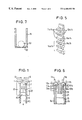
- FIG. 4 is a front elevational view of the dispensing kit according to FIG. 2, further showing a closure lid;
- FIG. 5 is a partially cut away, perspective view of one embodiment of a flexible portion according to the invention.
- FIG. 6 is a cross-sectional view of a top portion of the cartridge body of FIG. 2 showing the transition mechanisms.
- FIG. 7 is a cross-sectional, partially cut away view of a delivery mechanism in the dispensing kit according to the invention for dispensing solid tablets or capsules.
- FIG. 8 is a view similar to FIG. 2 showing an alternative embodiment for the delivery mechanism of the dispensing kit.
- FIG. 1 A schematic version of the principle of one embodiment of the urging device according to the invention is shown in FIG. 1, where the urging mechanism includes two flexible portions U 1 and U 2 which, when actuated in the direction of arrows A, move over transition mechanisms T and intermesh at an intermeshing region I for forming a consolidated longitudinal member C which pushes actuator AC in the actuating direction AD.
- This longitudinal member is guideable inside a guide housing G.
- the intermeshing region I may be formed in any suitable manner, such as through friction of flexible portions U 1 and U 2 , or through interlocking teeth, or any other conventional intermeshing mechanism as conventional in the art.
- the urging mechanism may be actuated in the actuating direction AD either directly by transition mechanisms T, which, by any suitable conventional mechanism, may be turned in the direction of arrows A to intermesh flexible portions U 1 and U 2 , or, in the alternative, this actuation may be effected by any other conventional means, such as a rod pushing flexible portions U 1 and U 2 in the actuating direction.
- the urging device shown in FIG. 1 advantageously allows the transfer of force through the use of a space saving urging mechanism having flexible portions which change direction during their actuation.
- An alternative embodiment of the principle of the urging device according to the invention may include a single flexible portion U 1 changing its direction at a corresponding transition mechanism, such that no intermeshing is necessary. Additionally, the flexible portion or portions according to the invention need not change their direction during actuation by 180 degrees as shown in FIG. 1, but may simply move in two distinctly identifiable directions made possible by a corresponding transition mechanism or mechanisms. It is further to be noted that the transition mechanisms can take any suitable conventional form, such as rollers, for effecting the change in direction of the flexible portions.
- a dispensing kit which, according to the invention includes two separately identifiable (i.e. distinct) parts, one including a reservoir or cartridge having a reservoir or cartridge body, and the other including a dispensing device having a dispensing device body adapted to receive the cartridge body therein.
- a dispensing kit 1 includes a dispensing device 3 having a dispensing device body or housing a dosing actuator 7 , and an urging mechanism including on the one hand flexible portions 9 a and 9 b having teeth 11 a and 11 b thereon, and, on the other hand, transition mechanisms 13 a and 13 b .
- the dispensing kit according to the invention further includes a dispensing reservoir, which, according to the invention, is a cartridge adapted to be introduced into and taken out of the dispensing device body.
- the body of the cartridge, or cartridge body 15 defines an opening 17 at one end thereof, and a head portion 19 at another end thereof.
- the cartridge further includes a cartridge actuator 21 , which, in the instant case, is a piston, disposed at head portion 19 .
- the actuator 7 is preferably shaped as a button-like piece, comparable to similar such pieces formed on actuated pens and pencils
- the dispensing device body can be provided with a clip (not shown) at the outside thereof, allowing the dispensing device and cartridge assembly to be conveniently available to the user, such as by being clipped to a pocket.
- the dispensing device and cartridge assembly may conveniently be shaped as a pen device for easy handling.
- cartridge body 15 has a content 23 which, in the shown embodiment, is a liquid.
- the content may include any fluid or solid apt to be dispensed, such as tablets or capsules.
- the cartridge is preferably sized for a content of up to 10 ml, preferably 3 ml.
- the cartridge body 15 is shown as having been introduced into the dispensing device body 5 , its opening being in registration with an opening 25 disposed at a neck portion 27 of the dispensing device body 5 .
- the dispensing actuator 7 is further shown as comprising a button biased by a rod biasing member 29 , which cooperates with a rod 31 for urging teeth is 11 a and 11 b forward, thus forming a rigid longitudinal member or rod 33 above cartridge actuator 21 of the cartridge.
- the dispensing device body 5 is composed of an inner housing portion 5 a which guides the flexible portions and fixes the cartridge body 15 after its insertion into the dispensing device body 5 , and of an outer housing portion 5 b , such a configuration imparting improved structural integrity to the dispensing device body.
- the urging mechanism further includes restoring indicator knobs 35 a and 35 b fixed to chains 9 a and 9 b respectively, these knobs being effective for restoring the position of the chains from the final position shown in FIG. 3 (the description of which follows further below) to the starting position as shown in FIG. 2 .
- Knobs 35 a and 35 b are guided in the dispensing device body in grooves 37 a and 37 b respectively, as better seen in FIG. 4 .
- the dispensing kit may comprise any suitable delivery mechanism 39 for allowing a dispensing of the content of the cartridge body 15 as is conventionally known in the art, such as drop-wise dispensing. Additionally, should the contents of the cartridge body be in the form of tablets or capsules, the delivery mechanism can take any suitable form for the individual dispensing of tablets or capsules as is conventionally known in the art, as will be explained in further detail below with respect to FIG. 7 .
- the delivery mechanism 39 in the embodiment of FIG. 2 takes the form of a no-drip delivery mechanism including, as part of the cartridge, a flexible closure member 41 fitted onto the opening 17 of the cartridge body 15 , and a guiding needle 43 attached to the cartridge body.
- the delivery mechanism 39 further includes a closure cap 45 having a flanged portion 47 for urging flexible closure member 41 onto the head of needle 43 .
- the delivery mechanism is brought into being by a perforation of a membrane 57 (which seals cartridge body 15 prior to its insertion into the dispensing device body) by a protrusion 55 on the flip-lid 53 , as will be explained in further detail with respect to FIG. 8 below.
- FIGS. 2 and 3 further show a microprocessor coupled to the dispensing actuator for controlling an actuation thereof thereby effecting a controlled movement of the urging mechanism.
- the microprocessor can be programmed to actuate the dispensing actuator a given set of times in order to dispense a prescribed or desired amount of the content 23 of cartridge body 15 .
- the user of the dispensing kit can advantageously program the microprocessor according to his/her needs, the microprocessor being of a conventional type as within the knowledge of one skilled in the art.
- FIG. 3 shows the dispensing kit of FIG. 2 with the urging device in its final position, that is, at a time when the dispensing device has effected a dispensing of the content 23 of cartridge body 15 to its maximum capacity.
- the flexible portions 9 a and 9 b have been moved by the dispensing actuator into an inner region of the cartridge body 15 forming the rigid member 33 thereon, knobs 35 a and 35 b further having moved to their topmost positions along grooves 37 a and 37 b.
- the outer housing body 5 b may have a graduation 49 thereon corresponding to a dosing of liquid 23 from cartridge body 15 by way of the actuation of dispensing actuator 7 . Further shown is one of the grooves 37 a/b , and its corresponding knob 35 a/b , which indicate in each instance the amount dispensed during actuation of dispensing actuator 7 , and the total amount dispensed by virtue of graduation 49 .
- FIG. 4 additionally shows an alternative closure cap 51 to the cap 45 shown in FIG. 2, this closure cap being openable and closeable by way of a flip-lid 53 as is conventional in the art.
- FIG. 5 shows a partially cut away perspective view of an embodiment of either of the flexible portions 9 a/b .
- this embodiment includes flexible portion each including a set 14 a/b of corresponding teeth 11 a/b thereon, each set 14 a/b including grooved teeth, 12 a/b followed by a solid tooth 11 a/b , the set 14 a/b repeating itself along each flexible portion 9 a/b for the length of the flexible portion
- the urging mechanism according to the invention may include intermeshing teeth 11 a and 11 b of the two flexible portions 9 a and 9 b , such as teeth being ordered according to sets 14 a/b shown in FIG. 5 .
- One embodiment for the transition mechanisms is further shown in FIG. 6, according to which each transition mechanism includes a direction changing member 57 a/b biased in a direction toward actuator 7 by biasing members 59 a and 59 b .
- the invention encompasses direction changing members and corresponding biasing members of any configuration as is conventional in the art for effecting a direction change of flexible portions 9 a and 9 b while further effecting a biasing of the direction changing members toward actuator 7 .
- the delivery mechanism may comprise a slitted flexible member 62 , made from a material such as rubber or the like, which allows an expulsion of the tablet from the cartridge body through pressure received thereon by an actuation of the urging device according to the invention, and which thereafter reassumes its original closed shape by virtue of material memory.
- the closure cap 51 may advantageously be formed in one embodiment of the invention as a cap having a needle-like protrusion 55 at an inner central region thereof.
- the cartridge is sealed by a membrane 57 before its insertion into the dispensing device body.
- the closure cap is placed onto the opening of the dispensing device body, the protrusion 55 thereby extending into a region of the opening of the dispenser device body and perforating the closure membrane 57 of the cartridge.
- the dispensing device and cartridge assembly are ready for dispensing the content of the cartridge from the opening created by a perforation of membrane 57 by protrusion 55 .
- the cartridge body 15 may be inserted into the dispensing device in any suitable way.
- the dispensing device body 5 may be made of two or more parts which may be disassembled in a suitable way for allowing an introduction of the cartridge body 15 therebetween before the parts are fastened back together.
- the closure cap 45 in the embodiment of FIGS. 2 and 3, or closure cap 51 in the embodiment of FIGS. 4 and 8, may be removed, allowing the introduction of the cartridge body 15 into the dispensing device body 5 . Thereafter, the closure caps may be repositioned on to the dispensing device body 5 as shown in the figures.
- the cartridge is introduced into the dispensing device body 5 when the urging device is in its initial position as shown in FIG. 2, its opening 17 being placed in registration with the opening in the dispensing device body 5 Should the flexible portions 9 a/b have been displaced from their initial positions, as indicated by a lowest position of restoring knobs 35 a and 35 b , these knobs can be pulled down manually.
- a delivery of the content 23 of cartridge body 15 may be effected by pushing downward on actuator 7 , which in turn presses down upon the teeth 11 a or 11 b of flexible portions 9 a or 9 b , depending on which tooth is exposed to rod 31 of actuator 7 .
- the pushing down of rod 31 therefore forces the teeth to intermesh with one another above cartridge actuator 21 , in the form of a rigid longitudinal member or rigid member 33 .
- Rigid member 33 then pushes actuator 21 downward, thus effecting a dispensing of the content of cartridge body 15 therefrom.
- the rod is thereafter biased upward by rod biasing member 29 into its initial, non-actuated position.
- rod 31 will be pushing on a solid tooth 10 a/b , pushing it downward, and emerging from the intermeshing region of the flexible portions 9 a/b through the grooves of grooved teeth 12 a/b to its initial position, having thus intermeshed the teeth 11 a/b in a first intermeshing stage.
- the teeth go through a secondary intermeshing stage through the action of transition mechanisms 13 a/b , as shown in FIG. 6 . It can be appreciated from FIG.
- biasing members 59 a and 59 b 6 that a pushing down of the teeth 11 a/b in the first intermeshing stage by rod 31 biases biasing members 59 a and 59 b downward, and that a restoring of the rod 31 to its initial position by way of rod biasing member 29 releases the biasing members 59 a and 59 b from a state of compression.
- the release of biasing members 59 a and 59 b causes a movement of the flexible positions in the intermeshing direction for a further intermeshing of teeth 11 a and 11 b in a second intermeshing stage, which ensures that a subsequent actuation of rod 31 will result in rod 31 acting on the next available solid tooth 10 a/b of the intermeshing flexible portions 9 a/b.
- the invention permits a simple, space saving alternative to force transfer mechanisms of the prior art.
- the urging device is configured for a step-wise delivery of the content of cartridge body 15
- the distances between given sets of teeth correspond to the actuation distance of the dispensing device for each push of dispensing actuator 7
- the no-drip delivery mechanism shown in FIGS. 2 and 3 functions as follows. To allow a delivery of the content 23 of cartridge body 15 , the actuator 7 is initially actuated as previously described, resulting in a delivery of the liquid content of cartridge body 15 onto delivery chamber 61 formed by the walls of the flexible closure member 41 . The volume of delivery chamber 61 would therefore correspond to one dose of the content of the cartridge body. Thereafter, closure cap 45 is pressed onto flexible closure member 41 for urging this member 41 at least partially past the head of needle 43 , and for thus changing the wall configuration of chamber 61 from configuration 41 ′ to configuration 41 ′′ as shown, and for reducing a volume of chamber 61 , thus effecting a delivery of liquid from the chamber.
- the above no-drip delivery mechanism is but one form for the delivery mechanism adapted to be used as part of the dispensing kit according to the invention, and may take any suitable conventional form, as an alternative to the inventive embodiment described above.
Landscapes
- Health & Medical Sciences (AREA)
- Public Health (AREA)
- Anesthesiology (AREA)
- Veterinary Medicine (AREA)
- Biomedical Technology (AREA)
- Heart & Thoracic Surgery (AREA)
- Hematology (AREA)
- Life Sciences & Earth Sciences (AREA)
- Animal Behavior & Ethology (AREA)
- General Health & Medical Sciences (AREA)
- Vascular Medicine (AREA)
- Engineering & Computer Science (AREA)
- Infusion, Injection, And Reservoir Apparatuses (AREA)
- Containers And Packaging Bodies Having A Special Means To Remove Contents (AREA)
- Coating Apparatus (AREA)
- Holders For Apparel And Elements Relating To Apparel (AREA)
- Control And Other Processes For Unpacking Of Materials (AREA)
- Perforating, Stamping-Out Or Severing By Means Other Than Cutting (AREA)
- Casting Or Compression Moulding Of Plastics Or The Like (AREA)
- Pinball Game Machines (AREA)
- Vending Machines For Individual Products (AREA)
- Adornments (AREA)
- Sampling And Sample Adjustment (AREA)
Applications Claiming Priority (3)
| Application Number | Priority Date | Filing Date | Title |
|---|---|---|---|
| DE19855764 | 1998-12-03 | ||
| DE19855764A DE19855764A1 (de) | 1998-12-03 | 1998-12-03 | Verwendung einer Karpule als Spender sowie Vorrichtung für diese Verwendung |
| PCT/EP1999/009198 WO2000032496A1 (en) | 1998-12-03 | 1999-11-26 | Flexible urging mechanism and dispensing kit incorporating same |
Publications (1)
| Publication Number | Publication Date |
|---|---|
| US6488183B1 true US6488183B1 (en) | 2002-12-03 |
Family
ID=7889830
Family Applications (1)
| Application Number | Title | Priority Date | Filing Date |
|---|---|---|---|
| US09/857,058 Expired - Fee Related US6488183B1 (en) | 1998-12-03 | 1999-11-26 | Flexible urging mechanism and dispensing kit incorporating same |
Country Status (10)
| Country | Link |
|---|---|
| US (1) | US6488183B1 (ja) |
| EP (1) | EP1202917B1 (ja) |
| JP (1) | JP3493342B2 (ja) |
| AT (1) | ATE237530T1 (ja) |
| AU (1) | AU1387000A (ja) |
| CA (1) | CA2348001A1 (ja) |
| DE (2) | DE19855764A1 (ja) |
| DK (1) | DK1202917T3 (ja) |
| ES (1) | ES2197715T3 (ja) |
| WO (1) | WO2000032496A1 (ja) |
Cited By (3)
| Publication number | Priority date | Publication date | Assignee | Title |
|---|---|---|---|---|
| US20050184102A1 (en) * | 2004-02-19 | 2005-08-25 | Patel Amar A. | Fluid dispenser with passive pressurization |
| US20100084422A1 (en) * | 2008-10-01 | 2010-04-08 | Ashley Robota | Sport Nutritional Supplement Dispenser |
| WO2016057647A1 (en) * | 2014-10-07 | 2016-04-14 | Westrock Mwv, Llc | Indexing dose dispensing device |
Families Citing this family (8)
| Publication number | Priority date | Publication date | Assignee | Title |
|---|---|---|---|---|
| DE20120329U1 (de) * | 2001-12-15 | 2002-04-04 | Kirst Werbung Gmbh | Schokoladenriegel- und Süssigkeitenspender |
| US6981621B2 (en) * | 2002-01-29 | 2006-01-03 | Zeev Brandeis | Caulking gun |
| DE102006038121A1 (de) * | 2006-08-14 | 2008-02-21 | Tecpharma Licensing Ag | Injektionsvorrichtung mit Echtzeitanzeige |
| WO2011029468A1 (de) * | 2009-09-08 | 2011-03-17 | Tecpharma Licensing Ag | Vorrichtung zur verabreichung eines injizierbaren produkts mit ausschüttungszähler |
| ES2531886T3 (es) * | 2012-07-31 | 2015-03-20 | Evondos Oy | Método y sistema para controlar la dispensación de medicamentos desde un dispensador de medicamentos |
| DE102018117305A1 (de) * | 2018-07-17 | 2020-01-23 | Uwe Weiss | Vorrichtung zum Einbringen von Mitteln in ein Erdreich |
| WO2023030877A1 (en) * | 2021-08-31 | 2023-03-09 | Shl Medical Ag | Plunger rod |
| WO2023154669A1 (en) * | 2022-02-10 | 2023-08-17 | Insulet Corporation | Drive device including flexible plunger shaft |
Citations (9)
| Publication number | Priority date | Publication date | Assignee | Title |
|---|---|---|---|---|
| US4318499A (en) | 1980-08-18 | 1982-03-09 | Hamilton Joel A | Retainer and propulsion apparatus carried in a self-contained handle for use with a removable cartridge |
| EP0051994A1 (en) | 1980-11-10 | 1982-05-19 | Merck & Co. Inc. | Medicament dispensing container |
| US4356938A (en) * | 1980-10-10 | 1982-11-02 | Kayser Steven J | Caulking gun with pressure release mechanism |
| US5062551A (en) | 1990-10-01 | 1991-11-05 | Delta Dispensing, Inc. | Postless pushup container |
| US5207659A (en) * | 1991-04-05 | 1993-05-04 | Societe Technique De Pulverisation - S.T.E.P. | Device for dispensing drops of small volume, in particular for ophthalmological care |
| US5511699A (en) * | 1993-09-27 | 1996-04-30 | Ao Research Institute | Manually operated tool mechanism |
| US5782633A (en) * | 1996-04-10 | 1998-07-21 | Muehlbauer; Ernst | Applicator for a dental compound |
| US6241412B1 (en) * | 1999-05-19 | 2001-06-05 | Norbert Spies | Cartridge toothbrush |
| US6293431B1 (en) * | 1998-03-05 | 2001-09-25 | Henkel Kommanditgesellschaft Auf Aktien | Container with a discharge nozzle |
Family Cites Families (11)
| Publication number | Priority date | Publication date | Assignee | Title |
|---|---|---|---|---|
| US1810249A (en) * | 1930-04-12 | 1931-06-16 | Edwin H Koehler | Cosmetic container |
| AT337907B (de) * | 1975-07-23 | 1977-07-25 | Neumann Heinz | Vorrichtung zur ausgabe von gegenstanden wie tabletten, kapseln, pillen od.dgl. |
| DD253572A1 (de) * | 1986-11-13 | 1988-01-27 | Medizin Labortechnik Veb K | Injektionsvorrichtung mit medikamentendepot |
| FR2628715B1 (fr) * | 1988-03-21 | 1990-08-17 | Ig Design Sarl | Distributeur d'objets a mouvement alternatif |
| FR2629988B1 (fr) | 1988-04-15 | 1990-08-10 | Oreal | Distributeur rechargeable comportant un piston translatable |
| FI921648A0 (fi) | 1992-04-13 | 1992-04-13 | Labsystems Oy | Stegpipett. |
| DE4310808C2 (de) * | 1993-04-02 | 1995-06-22 | Boehringer Mannheim Gmbh | System zur Dosierung von Flüssigkeiten |
| CA2109051A1 (en) | 1993-10-22 | 1995-04-23 | Norbert Hamy | Linear actuator |
| US5630527A (en) * | 1994-09-12 | 1997-05-20 | Philip Fishman Corporation | Electronically controlled, positive-displacement fluid dispenser |
| US5637095A (en) * | 1995-01-13 | 1997-06-10 | Minimed Inc. | Medication infusion pump with flexible drive plunger |
| DE19751219A1 (de) * | 1997-11-19 | 1999-05-27 | Vetter & Co Apotheker | Spritze, insbesondere vorgefüllte Spritze, oder Karpule |
-
1998
- 1998-12-03 DE DE19855764A patent/DE19855764A1/de not_active Ceased
-
1999
- 1999-11-26 CA CA002348001A patent/CA2348001A1/en not_active Abandoned
- 1999-11-26 US US09/857,058 patent/US6488183B1/en not_active Expired - Fee Related
- 1999-11-26 DE DE69907039T patent/DE69907039T2/de not_active Expired - Lifetime
- 1999-11-26 ES ES99973000T patent/ES2197715T3/es not_active Expired - Lifetime
- 1999-11-26 WO PCT/EP1999/009198 patent/WO2000032496A1/en active IP Right Grant
- 1999-11-26 DK DK99973000T patent/DK1202917T3/da active
- 1999-11-26 AU AU13870/00A patent/AU1387000A/en not_active Abandoned
- 1999-11-26 AT AT99973000T patent/ATE237530T1/de not_active IP Right Cessation
- 1999-11-26 EP EP99973000A patent/EP1202917B1/en not_active Expired - Lifetime
- 1999-11-26 JP JP2000585149A patent/JP3493342B2/ja not_active Expired - Fee Related
Patent Citations (9)
| Publication number | Priority date | Publication date | Assignee | Title |
|---|---|---|---|---|
| US4318499A (en) | 1980-08-18 | 1982-03-09 | Hamilton Joel A | Retainer and propulsion apparatus carried in a self-contained handle for use with a removable cartridge |
| US4356938A (en) * | 1980-10-10 | 1982-11-02 | Kayser Steven J | Caulking gun with pressure release mechanism |
| EP0051994A1 (en) | 1980-11-10 | 1982-05-19 | Merck & Co. Inc. | Medicament dispensing container |
| US5062551A (en) | 1990-10-01 | 1991-11-05 | Delta Dispensing, Inc. | Postless pushup container |
| US5207659A (en) * | 1991-04-05 | 1993-05-04 | Societe Technique De Pulverisation - S.T.E.P. | Device for dispensing drops of small volume, in particular for ophthalmological care |
| US5511699A (en) * | 1993-09-27 | 1996-04-30 | Ao Research Institute | Manually operated tool mechanism |
| US5782633A (en) * | 1996-04-10 | 1998-07-21 | Muehlbauer; Ernst | Applicator for a dental compound |
| US6293431B1 (en) * | 1998-03-05 | 2001-09-25 | Henkel Kommanditgesellschaft Auf Aktien | Container with a discharge nozzle |
| US6241412B1 (en) * | 1999-05-19 | 2001-06-05 | Norbert Spies | Cartridge toothbrush |
Cited By (5)
| Publication number | Priority date | Publication date | Assignee | Title |
|---|---|---|---|---|
| US20050184102A1 (en) * | 2004-02-19 | 2005-08-25 | Patel Amar A. | Fluid dispenser with passive pressurization |
| US7264141B2 (en) | 2004-02-19 | 2007-09-04 | Sanford, L.P. | Fluid dispenser with passive pressurization |
| US20100084422A1 (en) * | 2008-10-01 | 2010-04-08 | Ashley Robota | Sport Nutritional Supplement Dispenser |
| WO2016057647A1 (en) * | 2014-10-07 | 2016-04-14 | Westrock Mwv, Llc | Indexing dose dispensing device |
| US10773028B2 (en) | 2014-10-07 | 2020-09-15 | Silgan Dispensing Systems Corporation | Indexing dose dispensing device |
Also Published As
| Publication number | Publication date |
|---|---|
| CA2348001A1 (en) | 2000-06-08 |
| DE69907039T2 (de) | 2004-03-25 |
| JP2002531334A (ja) | 2002-09-24 |
| WO2000032496A1 (en) | 2000-06-08 |
| ATE237530T1 (de) | 2003-05-15 |
| EP1202917B1 (en) | 2003-04-16 |
| DE19855764A1 (de) | 2000-06-08 |
| DK1202917T3 (da) | 2003-08-04 |
| EP1202917A1 (en) | 2002-05-08 |
| AU1387000A (en) | 2000-06-19 |
| DE69907039D1 (de) | 2003-05-22 |
| JP3493342B2 (ja) | 2004-02-03 |
| ES2197715T3 (es) | 2004-01-01 |
Similar Documents
| Publication | Publication Date | Title |
|---|---|---|
| US5366113A (en) | Pill dispenser | |
| US5573341A (en) | Cosmetic composition dispenser | |
| RU2201121C2 (ru) | Дозирующая упаковка | |
| AU730050B2 (en) | Dose control dispenser | |
| US8540124B2 (en) | Dispensing pen | |
| US6488183B1 (en) | Flexible urging mechanism and dispensing kit incorporating same | |
| US3790048A (en) | Incremental dose dispenser | |
| JP4828431B2 (ja) | 投薬回数表示装置 | |
| US6533764B1 (en) | Twist housing apparatus for instilling a medication into an eye | |
| US3968902A (en) | Tablet dispenser | |
| US3993226A (en) | Dispenser for extrudable materials | |
| US20050036823A1 (en) | Dispenser for fluid materials | |
| KR100978528B1 (ko) | 알약 정량배출장치 | |
| NZ226579A (en) | Dispensing package for cream products: cams on cantilevered fingers produce reciprocating axial movement of elevator | |
| AU2007241452A1 (en) | Applicator with exchangeable reservoir | |
| EP0312165A2 (en) | Swivel-up type dispensing package | |
| JP2622309B2 (ja) | 散布器 | |
| US4522317A (en) | Dosage dispenser device for a viscous product | |
| EP2611483B1 (en) | Metering device and dispensing container | |
| EP3430939B1 (en) | Dispenser for storing and advancing a liquid | |
| DE4216541C2 (de) | Mehrfach verwendbarer Dosierspender | |
| GB2088828A (en) | Tablet dispenser | |
| CN102216174A (zh) | 容器 | |
| US20180207675A1 (en) | Selective metered dose dispensing device | |
| BE1019260A5 (nl) | Doseersysteem. |
Legal Events
| Date | Code | Title | Description |
|---|---|---|---|
| AS | Assignment |
Owner name: WEIMER PHARMA GMBH, GERMANY Free format text: ASSIGNMENT OF ASSIGNORS INTEREST;ASSIGNORS:BRAEUNINGER-WEIMER, WILLMAR;NEUHOLD, ARNOLD;REEL/FRAME:011951/0922;SIGNING DATES FROM 20010502 TO 20010509 Owner name: L+N PLAST VERTRIEBS GMBH, GERMANY Free format text: ASSIGNMENT OF ASSIGNORS INTEREST;ASSIGNORS:BRAEUNINGER-WEIMER, WILLMAR;NEUHOLD, ARNOLD;REEL/FRAME:011951/0922;SIGNING DATES FROM 20010502 TO 20010509 |
|
| CC | Certificate of correction | ||
| REMI | Maintenance fee reminder mailed | ||
| LAPS | Lapse for failure to pay maintenance fees | ||
| STCH | Information on status: patent discontinuation |
Free format text: PATENT EXPIRED DUE TO NONPAYMENT OF MAINTENANCE FEES UNDER 37 CFR 1.362 |
|
| FP | Lapsed due to failure to pay maintenance fee |
Effective date: 20061203 |