US6461769B1 - Organic electrolytic cell - Google Patents
Organic electrolytic cell Download PDFInfo
- Publication number
- US6461769B1 US6461769B1 US09/355,164 US35516499A US6461769B1 US 6461769 B1 US6461769 B1 US 6461769B1 US 35516499 A US35516499 A US 35516499A US 6461769 B1 US6461769 B1 US 6461769B1
- Authority
- US
- United States
- Prior art keywords
- lithium
- negative electrode
- positive electrode
- cell
- electrode
- Prior art date
- Legal status (The legal status is an assumption and is not a legal conclusion. Google has not performed a legal analysis and makes no representation as to the accuracy of the status listed.)
- Expired - Lifetime
Links
- 229910052744 lithium Inorganic materials 0.000 claims abstract description 278
- WHXSMMKQMYFTQS-UHFFFAOYSA-N Lithium Chemical compound [Li] WHXSMMKQMYFTQS-UHFFFAOYSA-N 0.000 claims abstract description 203
- 239000011149 active material Substances 0.000 claims abstract description 48
- 239000008151 electrolyte solution Substances 0.000 claims abstract description 47
- 239000011148 porous material Substances 0.000 claims abstract description 16
- 239000000243 solution Substances 0.000 claims abstract description 13
- 239000003960 organic solvent Substances 0.000 claims abstract description 10
- 229910003002 lithium salt Inorganic materials 0.000 claims abstract description 6
- 159000000002 lithium salts Chemical class 0.000 claims abstract description 6
- 239000000758 substrate Substances 0.000 claims description 23
- OKTJSMMVPCPJKN-UHFFFAOYSA-N Carbon Chemical compound [C] OKTJSMMVPCPJKN-UHFFFAOYSA-N 0.000 claims description 18
- 229920000642 polymer Polymers 0.000 claims description 13
- 125000003118 aryl group Chemical group 0.000 claims description 12
- 238000009833 condensation Methods 0.000 claims description 10
- 230000005494 condensation Effects 0.000 claims description 10
- 229920003026 Acene Polymers 0.000 claims description 9
- 229910052799 carbon Inorganic materials 0.000 claims description 9
- UFHFLCQGNIYNRP-UHFFFAOYSA-N Hydrogen Chemical compound [H][H] UFHFLCQGNIYNRP-UHFFFAOYSA-N 0.000 claims description 6
- HBBGRARXTFLTSG-UHFFFAOYSA-N Lithium ion Chemical compound [Li+] HBBGRARXTFLTSG-UHFFFAOYSA-N 0.000 claims description 6
- 239000001257 hydrogen Substances 0.000 claims description 6
- 229910052739 hydrogen Inorganic materials 0.000 claims description 6
- 229910001416 lithium ion Inorganic materials 0.000 claims description 6
- 210000004027 cell Anatomy 0.000 description 208
- 239000011888 foil Substances 0.000 description 27
- 229910052751 metal Inorganic materials 0.000 description 22
- 239000002184 metal Substances 0.000 description 22
- 239000010935 stainless steel Substances 0.000 description 20
- 229910001220 stainless steel Inorganic materials 0.000 description 20
- -1 phenol Chemical class 0.000 description 19
- 238000000034 method Methods 0.000 description 13
- 229910052782 aluminium Inorganic materials 0.000 description 12
- XAGFODPZIPBFFR-UHFFFAOYSA-N aluminium Chemical compound [Al] XAGFODPZIPBFFR-UHFFFAOYSA-N 0.000 description 12
- 239000004020 conductor Substances 0.000 description 12
- 239000002002 slurry Substances 0.000 description 12
- 239000011230 binding agent Substances 0.000 description 11
- 229910052731 fluorine Inorganic materials 0.000 description 11
- 229910044991 metal oxide Inorganic materials 0.000 description 10
- YCKRFDGAMUMZLT-UHFFFAOYSA-N Fluorine atom Chemical compound [F] YCKRFDGAMUMZLT-UHFFFAOYSA-N 0.000 description 9
- PXHVJJICTQNCMI-UHFFFAOYSA-N Nickel Chemical compound [Ni] PXHVJJICTQNCMI-UHFFFAOYSA-N 0.000 description 9
- 239000002033 PVDF binder Substances 0.000 description 9
- 239000004743 Polypropylene Substances 0.000 description 9
- 239000011737 fluorine Substances 0.000 description 9
- 229920001155 polypropylene Polymers 0.000 description 9
- 229920002981 polyvinylidene fluoride Polymers 0.000 description 9
- RYGMFSIKBFXOCR-UHFFFAOYSA-N Copper Chemical compound [Cu] RYGMFSIKBFXOCR-UHFFFAOYSA-N 0.000 description 8
- 239000000463 material Substances 0.000 description 8
- 239000000843 powder Substances 0.000 description 8
- 230000000052 comparative effect Effects 0.000 description 7
- 238000010438 heat treatment Methods 0.000 description 7
- 238000003466 welding Methods 0.000 description 7
- WSFSSNUMVMOOMR-UHFFFAOYSA-N Formaldehyde Chemical compound O=C WSFSSNUMVMOOMR-UHFFFAOYSA-N 0.000 description 6
- GNTDGMZSJNCJKK-UHFFFAOYSA-N divanadium pentaoxide Chemical compound O=[V](=O)O[V](=O)=O GNTDGMZSJNCJKK-UHFFFAOYSA-N 0.000 description 6
- ISWSIDIOOBJBQZ-UHFFFAOYSA-N Phenol Chemical compound OC1=CC=CC=C1 ISWSIDIOOBJBQZ-UHFFFAOYSA-N 0.000 description 5
- 239000003575 carbonaceous material Substances 0.000 description 5
- 229920001577 copolymer Polymers 0.000 description 5
- 229910052802 copper Inorganic materials 0.000 description 5
- 239000010949 copper Substances 0.000 description 5
- 239000003792 electrolyte Substances 0.000 description 5
- 239000010439 graphite Substances 0.000 description 5
- 229910002804 graphite Inorganic materials 0.000 description 5
- 238000000465 moulding Methods 0.000 description 5
- 229910032387 LiCoO2 Inorganic materials 0.000 description 4
- 239000006230 acetylene black Substances 0.000 description 4
- 150000004945 aromatic hydrocarbons Chemical class 0.000 description 4
- 229920001940 conductive polymer Polymers 0.000 description 4
- 238000004519 manufacturing process Methods 0.000 description 4
- 239000007773 negative electrode material Substances 0.000 description 4
- 229910052759 nickel Inorganic materials 0.000 description 4
- WEVYAHXRMPXWCK-UHFFFAOYSA-N Acetonitrile Chemical compound CC#N WEVYAHXRMPXWCK-UHFFFAOYSA-N 0.000 description 3
- YMWUJEATGCHHMB-UHFFFAOYSA-N Dichloromethane Chemical compound ClCCl YMWUJEATGCHHMB-UHFFFAOYSA-N 0.000 description 3
- SECXISVLQFMRJM-UHFFFAOYSA-N N-Methylpyrrolidone Chemical compound CN1CCCC1=O SECXISVLQFMRJM-UHFFFAOYSA-N 0.000 description 3
- 239000004698 Polyethylene Substances 0.000 description 3
- VYPSYNLAJGMNEJ-UHFFFAOYSA-N Silicium dioxide Chemical compound O=[Si]=O VYPSYNLAJGMNEJ-UHFFFAOYSA-N 0.000 description 3
- YXFVVABEGXRONW-UHFFFAOYSA-N Toluene Chemical compound CC1=CC=CC=C1 YXFVVABEGXRONW-UHFFFAOYSA-N 0.000 description 3
- 150000001299 aldehydes Chemical class 0.000 description 3
- NVIVJPRCKQTWLY-UHFFFAOYSA-N cobalt nickel Chemical compound [Co][Ni][Co] NVIVJPRCKQTWLY-UHFFFAOYSA-N 0.000 description 3
- IVMYJDGYRUAWML-UHFFFAOYSA-N cobalt(ii) oxide Chemical class [Co]=O IVMYJDGYRUAWML-UHFFFAOYSA-N 0.000 description 3
- 239000011889 copper foil Substances 0.000 description 3
- 230000006866 deterioration Effects 0.000 description 3
- 150000002739 metals Chemical class 0.000 description 3
- 239000000203 mixture Substances 0.000 description 3
- 229910000480 nickel oxide Inorganic materials 0.000 description 3
- GNRSAWUEBMWBQH-UHFFFAOYSA-N oxonickel Chemical class [Ni]=O GNRSAWUEBMWBQH-UHFFFAOYSA-N 0.000 description 3
- 229920000573 polyethylene Polymers 0.000 description 3
- XOLBLPGZBRYERU-UHFFFAOYSA-N tin dioxide Chemical compound O=[Sn]=O XOLBLPGZBRYERU-UHFFFAOYSA-N 0.000 description 3
- 229910052723 transition metal Inorganic materials 0.000 description 3
- 150000003624 transition metals Chemical class 0.000 description 3
- BQCIDUSAKPWEOX-UHFFFAOYSA-N 1,1-Difluoroethene Chemical compound FC(F)=C BQCIDUSAKPWEOX-UHFFFAOYSA-N 0.000 description 2
- YEJRWHAVMIAJKC-UHFFFAOYSA-N 4-Butyrolactone Chemical compound O=C1CCCO1 YEJRWHAVMIAJKC-UHFFFAOYSA-N 0.000 description 2
- IKHGUXGNUITLKF-UHFFFAOYSA-N Acetaldehyde Chemical compound CC=O IKHGUXGNUITLKF-UHFFFAOYSA-N 0.000 description 2
- PAYRUJLWNCNPSJ-UHFFFAOYSA-N Aniline Chemical compound NC1=CC=CC=C1 PAYRUJLWNCNPSJ-UHFFFAOYSA-N 0.000 description 2
- 238000004438 BET method Methods 0.000 description 2
- OIFBSDVPJOWBCH-UHFFFAOYSA-N Diethyl carbonate Chemical compound CCOC(=O)OCC OIFBSDVPJOWBCH-UHFFFAOYSA-N 0.000 description 2
- KMTRUDSVKNLOMY-UHFFFAOYSA-N Ethylene carbonate Chemical compound O=C1OCCO1 KMTRUDSVKNLOMY-UHFFFAOYSA-N 0.000 description 2
- 229910001290 LiPF6 Inorganic materials 0.000 description 2
- 229910001091 LixCoO2 Inorganic materials 0.000 description 2
- 229910003007 LixMnO2 Inorganic materials 0.000 description 2
- 229910015867 LixMyOz Inorganic materials 0.000 description 2
- 229910014149 LixNiO2 Inorganic materials 0.000 description 2
- CTQNGGLPUBDAKN-UHFFFAOYSA-N O-Xylene Chemical compound CC1=CC=CC=C1C CTQNGGLPUBDAKN-UHFFFAOYSA-N 0.000 description 2
- WYURNTSHIVDZCO-UHFFFAOYSA-N Tetrahydrofuran Chemical compound C1CCOC1 WYURNTSHIVDZCO-UHFFFAOYSA-N 0.000 description 2
- 239000012298 atmosphere Substances 0.000 description 2
- 229910017052 cobalt Inorganic materials 0.000 description 2
- 239000010941 cobalt Substances 0.000 description 2
- GUTLYIVDDKVIGB-UHFFFAOYSA-N cobalt atom Chemical compound [Co] GUTLYIVDDKVIGB-UHFFFAOYSA-N 0.000 description 2
- 210000001787 dendrite Anatomy 0.000 description 2
- 238000006056 electrooxidation reaction Methods 0.000 description 2
- HYBBIBNJHNGZAN-UHFFFAOYSA-N furfural Chemical compound O=CC1=CC=CO1 HYBBIBNJHNGZAN-UHFFFAOYSA-N 0.000 description 2
- 125000002887 hydroxy group Chemical group [H]O* 0.000 description 2
- 238000009776 industrial production Methods 0.000 description 2
- NUJOXMJBOLGQSY-UHFFFAOYSA-N manganese dioxide Chemical compound O=[Mn]=O NUJOXMJBOLGQSY-UHFFFAOYSA-N 0.000 description 2
- 150000004706 metal oxides Chemical class 0.000 description 2
- 239000011259 mixed solution Substances 0.000 description 2
- 230000001590 oxidative effect Effects 0.000 description 2
- 229920001568 phenolic resin Polymers 0.000 description 2
- 150000002989 phenols Chemical class 0.000 description 2
- 239000007774 positive electrode material Substances 0.000 description 2
- 229920005989 resin Polymers 0.000 description 2
- 239000011347 resin Substances 0.000 description 2
- 239000002904 solvent Substances 0.000 description 2
- 210000000352 storage cell Anatomy 0.000 description 2
- 150000004763 sulfides Chemical class 0.000 description 2
- 229920005992 thermoplastic resin Polymers 0.000 description 2
- 239000008096 xylene Substances 0.000 description 2
- JIAARYAFYJHUJI-UHFFFAOYSA-L zinc dichloride Chemical compound [Cl-].[Cl-].[Zn+2] JIAARYAFYJHUJI-UHFFFAOYSA-L 0.000 description 2
- WNXJIVFYUVYPPR-UHFFFAOYSA-N 1,3-dioxolane Chemical compound C1COCO1 WNXJIVFYUVYPPR-UHFFFAOYSA-N 0.000 description 1
- KJCVRFUGPWSIIH-UHFFFAOYSA-N 1-naphthol Chemical class C1=CC=C2C(O)=CC=CC2=C1 KJCVRFUGPWSIIH-UHFFFAOYSA-N 0.000 description 1
- MQCPOLNSJCWPGT-UHFFFAOYSA-N 2,2'-Bisphenol F Chemical class OC1=CC=CC=C1CC1=CC=CC=C1O MQCPOLNSJCWPGT-UHFFFAOYSA-N 0.000 description 1
- KXGFMDJXCMQABM-UHFFFAOYSA-N 2-methoxy-6-methylphenol Chemical compound [CH]OC1=CC=CC([CH])=C1O KXGFMDJXCMQABM-UHFFFAOYSA-N 0.000 description 1
- QTWJRLJHJPIABL-UHFFFAOYSA-N 2-methylphenol;3-methylphenol;4-methylphenol Chemical compound CC1=CC=C(O)C=C1.CC1=CC=CC(O)=C1.CC1=CC=CC=C1O QTWJRLJHJPIABL-UHFFFAOYSA-N 0.000 description 1
- 229910000838 Al alloy Inorganic materials 0.000 description 1
- 229910014451 C6Li Inorganic materials 0.000 description 1
- XTHFKEDIFFGKHM-UHFFFAOYSA-N Dimethoxyethane Chemical compound COCCOC XTHFKEDIFFGKHM-UHFFFAOYSA-N 0.000 description 1
- VEXZGXHMUGYJMC-UHFFFAOYSA-N Hydrochloric acid Chemical compound Cl VEXZGXHMUGYJMC-UHFFFAOYSA-N 0.000 description 1
- 229910000733 Li alloy Inorganic materials 0.000 description 1
- PWHULOQIROXLJO-UHFFFAOYSA-N Manganese Chemical compound [Mn] PWHULOQIROXLJO-UHFFFAOYSA-N 0.000 description 1
- 229920000877 Melamine resin Polymers 0.000 description 1
- 229910003307 Ni-Cd Inorganic materials 0.000 description 1
- 229910003092 TiS2 Inorganic materials 0.000 description 1
- RTAQQCXQSZGOHL-UHFFFAOYSA-N Titanium Chemical compound [Ti] RTAQQCXQSZGOHL-UHFFFAOYSA-N 0.000 description 1
- XSQUKJJJFZCRTK-UHFFFAOYSA-N Urea Chemical group NC(N)=O XSQUKJJJFZCRTK-UHFFFAOYSA-N 0.000 description 1
- 238000002441 X-ray diffraction Methods 0.000 description 1
- JFBZPFYRPYOZCQ-UHFFFAOYSA-N [Li].[Al] Chemical compound [Li].[Al] JFBZPFYRPYOZCQ-UHFFFAOYSA-N 0.000 description 1
- 125000000217 alkyl group Chemical group 0.000 description 1
- 229910045601 alloy Inorganic materials 0.000 description 1
- 239000000956 alloy Substances 0.000 description 1
- 239000004202 carbamide Chemical group 0.000 description 1
- 229910052681 coesite Inorganic materials 0.000 description 1
- 150000001875 compounds Chemical class 0.000 description 1
- 238000010276 construction Methods 0.000 description 1
- 229930003836 cresol Natural products 0.000 description 1
- 229910052906 cristobalite Inorganic materials 0.000 description 1
- IEJIGPNLZYLLBP-UHFFFAOYSA-N dimethyl carbonate Chemical compound COC(=O)OC IEJIGPNLZYLLBP-UHFFFAOYSA-N 0.000 description 1
- 230000008034 disappearance Effects 0.000 description 1
- 229920001971 elastomer Polymers 0.000 description 1
- 239000007772 electrode material Substances 0.000 description 1
- 239000004744 fabric Substances 0.000 description 1
- 239000000835 fiber Substances 0.000 description 1
- SLGWESQGEUXWJQ-UHFFFAOYSA-N formaldehyde;phenol Chemical compound O=C.OC1=CC=CC=C1 SLGWESQGEUXWJQ-UHFFFAOYSA-N 0.000 description 1
- 239000007849 furan resin Substances 0.000 description 1
- 239000003365 glass fiber Substances 0.000 description 1
- 230000005484 gravity Effects 0.000 description 1
- 125000004435 hydrogen atom Chemical group [H]* 0.000 description 1
- 150000005352 hydroxybiphenyls Chemical class 0.000 description 1
- 229910017053 inorganic salt Inorganic materials 0.000 description 1
- 239000007788 liquid Substances 0.000 description 1
- 150000002641 lithium Chemical class 0.000 description 1
- 239000001989 lithium alloy Substances 0.000 description 1
- 229910001540 lithium hexafluoroarsenate(V) Inorganic materials 0.000 description 1
- HSZCZNFXUDYRKD-UHFFFAOYSA-M lithium iodide Inorganic materials [Li+].[I-] HSZCZNFXUDYRKD-UHFFFAOYSA-M 0.000 description 1
- MHCFAGZWMAWTNR-UHFFFAOYSA-M lithium perchlorate Chemical compound [Li+].[O-]Cl(=O)(=O)=O MHCFAGZWMAWTNR-UHFFFAOYSA-M 0.000 description 1
- 229910001486 lithium perchlorate Inorganic materials 0.000 description 1
- 229910001496 lithium tetrafluoroborate Inorganic materials 0.000 description 1
- 229910052748 manganese Inorganic materials 0.000 description 1
- 239000011572 manganese Substances 0.000 description 1
- WPBNNNQJVZRUHP-UHFFFAOYSA-L manganese(2+);methyl n-[[2-(methoxycarbonylcarbamothioylamino)phenyl]carbamothioyl]carbamate;n-[2-(sulfidocarbothioylamino)ethyl]carbamodithioate Chemical compound [Mn+2].[S-]C(=S)NCCNC([S-])=S.COC(=O)NC(=S)NC1=CC=CC=C1NC(=S)NC(=O)OC WPBNNNQJVZRUHP-UHFFFAOYSA-L 0.000 description 1
- JDSHMPZPIAZGSV-UHFFFAOYSA-N melamine Chemical group NC1=NC(N)=NC(N)=N1 JDSHMPZPIAZGSV-UHFFFAOYSA-N 0.000 description 1
- WSFSSNUMVMOOMR-NJFSPNSNSA-N methanone Chemical compound O=[14CH2] WSFSSNUMVMOOMR-NJFSPNSNSA-N 0.000 description 1
- 239000012046 mixed solvent Substances 0.000 description 1
- 239000012299 nitrogen atmosphere Substances 0.000 description 1
- 239000004745 nonwoven fabric Substances 0.000 description 1
- 229920003986 novolac Polymers 0.000 description 1
- 239000002245 particle Substances 0.000 description 1
- 230000035699 permeability Effects 0.000 description 1
- QQONPFPTGQHPMA-UHFFFAOYSA-N propylene Natural products CC=C QQONPFPTGQHPMA-UHFFFAOYSA-N 0.000 description 1
- RUOJZAUFBMNUDX-UHFFFAOYSA-N propylene carbonate Chemical compound CC1COC(=O)O1 RUOJZAUFBMNUDX-UHFFFAOYSA-N 0.000 description 1
- 125000004805 propylene group Chemical group [H]C([H])([H])C([H])([*:1])C([H])([H])[*:2] 0.000 description 1
- 229920003987 resole Polymers 0.000 description 1
- 239000004065 semiconductor Substances 0.000 description 1
- HBMJWWWQQXIZIP-UHFFFAOYSA-N silicon carbide Chemical compound [Si+]#[C-] HBMJWWWQQXIZIP-UHFFFAOYSA-N 0.000 description 1
- 229910010271 silicon carbide Inorganic materials 0.000 description 1
- 239000000377 silicon dioxide Substances 0.000 description 1
- 229910052814 silicon oxide Inorganic materials 0.000 description 1
- 239000007787 solid Substances 0.000 description 1
- 229910052682 stishovite Inorganic materials 0.000 description 1
- 239000000126 substance Substances 0.000 description 1
- HXJUTPCZVOIRIF-UHFFFAOYSA-N sulfolane Chemical compound O=S1(=O)CCCC1 HXJUTPCZVOIRIF-UHFFFAOYSA-N 0.000 description 1
- YLQBMQCUIZJEEH-UHFFFAOYSA-N tetrahydrofuran Natural products C=1C=COC=1 YLQBMQCUIZJEEH-UHFFFAOYSA-N 0.000 description 1
- 229910001887 tin oxide Inorganic materials 0.000 description 1
- 239000010936 titanium Substances 0.000 description 1
- 229910052719 titanium Inorganic materials 0.000 description 1
- 229910052905 tridymite Inorganic materials 0.000 description 1
- 229910052720 vanadium Inorganic materials 0.000 description 1
- GPPXJZIENCGNKB-UHFFFAOYSA-N vanadium Chemical compound [V]#[V] GPPXJZIENCGNKB-UHFFFAOYSA-N 0.000 description 1
- 238000005406 washing Methods 0.000 description 1
- XLYOFNOQVPJJNP-UHFFFAOYSA-N water Substances O XLYOFNOQVPJJNP-UHFFFAOYSA-N 0.000 description 1
- 125000002256 xylenyl group Chemical class C1(C(C=CC=C1)C)(C)* 0.000 description 1
- 235000005074 zinc chloride Nutrition 0.000 description 1
- 239000011592 zinc chloride Substances 0.000 description 1
Images


Classifications
-
- H—ELECTRICITY
- H01—ELECTRIC ELEMENTS
- H01M—PROCESSES OR MEANS, e.g. BATTERIES, FOR THE DIRECT CONVERSION OF CHEMICAL ENERGY INTO ELECTRICAL ENERGY
- H01M10/00—Secondary cells; Manufacture thereof
- H01M10/05—Accumulators with non-aqueous electrolyte
- H01M10/058—Construction or manufacture
- H01M10/0587—Construction or manufacture of accumulators having only wound construction elements, i.e. wound positive electrodes, wound negative electrodes and wound separators
-
- H—ELECTRICITY
- H01—ELECTRIC ELEMENTS
- H01M—PROCESSES OR MEANS, e.g. BATTERIES, FOR THE DIRECT CONVERSION OF CHEMICAL ENERGY INTO ELECTRICAL ENERGY
- H01M10/00—Secondary cells; Manufacture thereof
- H01M10/04—Construction or manufacture in general
- H01M10/0413—Large-sized flat cells or batteries for motive or stationary systems with plate-like electrodes
-
- H—ELECTRICITY
- H01—ELECTRIC ELEMENTS
- H01M—PROCESSES OR MEANS, e.g. BATTERIES, FOR THE DIRECT CONVERSION OF CHEMICAL ENERGY INTO ELECTRICAL ENERGY
- H01M10/00—Secondary cells; Manufacture thereof
- H01M10/05—Accumulators with non-aqueous electrolyte
- H01M10/052—Li-accumulators
- H01M10/0525—Rocking-chair batteries, i.e. batteries with lithium insertion or intercalation in both electrodes; Lithium-ion batteries
-
- H—ELECTRICITY
- H01—ELECTRIC ELEMENTS
- H01M—PROCESSES OR MEANS, e.g. BATTERIES, FOR THE DIRECT CONVERSION OF CHEMICAL ENERGY INTO ELECTRICAL ENERGY
- H01M10/00—Secondary cells; Manufacture thereof
- H01M10/05—Accumulators with non-aqueous electrolyte
- H01M10/056—Accumulators with non-aqueous electrolyte characterised by the materials used as electrolytes, e.g. mixed inorganic/organic electrolytes
- H01M10/0564—Accumulators with non-aqueous electrolyte characterised by the materials used as electrolytes, e.g. mixed inorganic/organic electrolytes the electrolyte being constituted of organic materials only
- H01M10/0566—Liquid materials
-
- H—ELECTRICITY
- H01—ELECTRIC ELEMENTS
- H01M—PROCESSES OR MEANS, e.g. BATTERIES, FOR THE DIRECT CONVERSION OF CHEMICAL ENERGY INTO ELECTRICAL ENERGY
- H01M10/00—Secondary cells; Manufacture thereof
- H01M10/05—Accumulators with non-aqueous electrolyte
- H01M10/058—Construction or manufacture
- H01M10/0585—Construction or manufacture of accumulators having only flat construction elements, i.e. flat positive electrodes, flat negative electrodes and flat separators
-
- H—ELECTRICITY
- H01—ELECTRIC ELEMENTS
- H01M—PROCESSES OR MEANS, e.g. BATTERIES, FOR THE DIRECT CONVERSION OF CHEMICAL ENERGY INTO ELECTRICAL ENERGY
- H01M4/00—Electrodes
- H01M4/02—Electrodes composed of, or comprising, active material
- H01M4/13—Electrodes for accumulators with non-aqueous electrolyte, e.g. for lithium-accumulators; Processes of manufacture thereof
- H01M4/137—Electrodes based on electro-active polymers
-
- H—ELECTRICITY
- H01—ELECTRIC ELEMENTS
- H01M—PROCESSES OR MEANS, e.g. BATTERIES, FOR THE DIRECT CONVERSION OF CHEMICAL ENERGY INTO ELECTRICAL ENERGY
- H01M4/00—Electrodes
- H01M4/02—Electrodes composed of, or comprising, active material
- H01M4/36—Selection of substances as active materials, active masses, active liquids
- H01M4/60—Selection of substances as active materials, active masses, active liquids of organic compounds
- H01M4/602—Polymers
-
- H—ELECTRICITY
- H01—ELECTRIC ELEMENTS
- H01M—PROCESSES OR MEANS, e.g. BATTERIES, FOR THE DIRECT CONVERSION OF CHEMICAL ENERGY INTO ELECTRICAL ENERGY
- H01M4/00—Electrodes
- H01M4/02—Electrodes composed of, or comprising, active material
- H01M4/64—Carriers or collectors
- H01M4/70—Carriers or collectors characterised by shape or form
- H01M4/72—Grids
- H01M4/74—Meshes or woven material; Expanded metal
- H01M4/742—Meshes or woven material; Expanded metal perforated material
-
- H—ELECTRICITY
- H01—ELECTRIC ELEMENTS
- H01M—PROCESSES OR MEANS, e.g. BATTERIES, FOR THE DIRECT CONVERSION OF CHEMICAL ENERGY INTO ELECTRICAL ENERGY
- H01M10/00—Secondary cells; Manufacture thereof
- H01M10/05—Accumulators with non-aqueous electrolyte
- H01M10/056—Accumulators with non-aqueous electrolyte characterised by the materials used as electrolytes, e.g. mixed inorganic/organic electrolytes
- H01M10/0564—Accumulators with non-aqueous electrolyte characterised by the materials used as electrolytes, e.g. mixed inorganic/organic electrolytes the electrolyte being constituted of organic materials only
- H01M10/0566—Liquid materials
- H01M10/0569—Liquid materials characterised by the solvents
-
- H—ELECTRICITY
- H01—ELECTRIC ELEMENTS
- H01M—PROCESSES OR MEANS, e.g. BATTERIES, FOR THE DIRECT CONVERSION OF CHEMICAL ENERGY INTO ELECTRICAL ENERGY
- H01M10/00—Secondary cells; Manufacture thereof
- H01M10/42—Methods or arrangements for servicing or maintenance of secondary cells or secondary half-cells
- H01M2010/4292—Aspects relating to capacity ratio of electrodes/electrolyte or anode/cathode
-
- H—ELECTRICITY
- H01—ELECTRIC ELEMENTS
- H01M—PROCESSES OR MEANS, e.g. BATTERIES, FOR THE DIRECT CONVERSION OF CHEMICAL ENERGY INTO ELECTRICAL ENERGY
- H01M4/00—Electrodes
- H01M4/02—Electrodes composed of, or comprising, active material
- H01M4/04—Processes of manufacture in general
-
- Y—GENERAL TAGGING OF NEW TECHNOLOGICAL DEVELOPMENTS; GENERAL TAGGING OF CROSS-SECTIONAL TECHNOLOGIES SPANNING OVER SEVERAL SECTIONS OF THE IPC; TECHNICAL SUBJECTS COVERED BY FORMER USPC CROSS-REFERENCE ART COLLECTIONS [XRACs] AND DIGESTS
- Y02—TECHNOLOGIES OR APPLICATIONS FOR MITIGATION OR ADAPTATION AGAINST CLIMATE CHANGE
- Y02E—REDUCTION OF GREENHOUSE GAS [GHG] EMISSIONS, RELATED TO ENERGY GENERATION, TRANSMISSION OR DISTRIBUTION
- Y02E60/00—Enabling technologies; Technologies with a potential or indirect contribution to GHG emissions mitigation
- Y02E60/10—Energy storage using batteries
-
- Y—GENERAL TAGGING OF NEW TECHNOLOGICAL DEVELOPMENTS; GENERAL TAGGING OF CROSS-SECTIONAL TECHNOLOGIES SPANNING OVER SEVERAL SECTIONS OF THE IPC; TECHNICAL SUBJECTS COVERED BY FORMER USPC CROSS-REFERENCE ART COLLECTIONS [XRACs] AND DIGESTS
- Y02—TECHNOLOGIES OR APPLICATIONS FOR MITIGATION OR ADAPTATION AGAINST CLIMATE CHANGE
- Y02P—CLIMATE CHANGE MITIGATION TECHNOLOGIES IN THE PRODUCTION OR PROCESSING OF GOODS
- Y02P70/00—Climate change mitigation technologies in the production process for final industrial or consumer products
- Y02P70/50—Manufacturing or production processes characterised by the final manufactured product
Definitions
- the present invention relates to an organic electrolytic cell, which has a high capacity and high voltage and is superior in charge and discharge characteristics and safety.
- a cell wherein a carbon material such as graphite is used as the negative electrode and a lithium-containing metallic oxide such as LiCoO 2 is used as the positive electrode.
- This cell is a so-called rocking chair-type cell wherein, after assembly of the cell, lithium is supplied from the lithium-containing metallic oxide as the positive electrode to the negative electrode through charge, and lithium of the negative electrode is returned to the positive electrode through discharge.
- the cell is characterized by a high voltage and high capacity, the high energy density as an advantage of the lithium cells has not been obtained.
- the lithium-containing metallic oxide As the positive electrode, it is an essential feature to use the lithium-containing metallic oxide as the positive electrode. Therefore, when using metallic oxides (e.g. V 2 O 5 , MnO 2 , TiS 2 , etc.), metallic sulfides, electrically conductive polymers (e.g. polyacene organic semiconductor, etc.) or the like proposed as the positive electrode material for lithium secondary cells, it is necessary to previously carry lithium on the positive or negative electrode. To obtain these positive electrode materials, there is required a method of carrying lithium, practically and simply.
- metallic oxides e.g. V 2 O 5 , MnO 2 , TiS 2 , etc.
- electrically conductive polymers e.g. polyacene organic semiconductor, etc.
- an infusible and insoluble substrate having a polyacene skeletal structure and a hydrogen/carbon atomic ratio of 0.50 to 0.05, the substrate being a heat-treated product of an aromatic condensation polymer, is capable of doping with lithium up to C 2 Li (Synthetic Metals, 73 (1995) P273).
- the above locking chair-type cell wherein this infusible and insoluble substrate is used as the negative electrode and the lithium-containing metallic oxide as the positive electrode can attain a capacity higher than that in the case of the carbon material after assembly, but there still remains an unsatisfactory respect in its capacity.
- PCT Publication No. WO95/8852 whose application was filed by the present applicant, has proposed an organic electrolytic cell comprising a positive electrode, a negative electrode and a solution of lithium salt in an aprotic organic solvent as an electrolytic solution, wherein the positive electrode contains a metallic oxide, the negative electrode is an infusible and insoluble substrate having a polyacene skeletal structure and a hydrogen/carbon atomic ratio of 0.50 to 0.05, the substrate being a heat-treated product of an aromatic condensation polymer, and the total amount of lithium contained in the cell is not less than 500 mAh/g and the amount of lithium originating in the negative electrode is not less than 100 mAh/g, based on the infusible and insoluble substrate as the negative electrode.
- the positive electrode contains a metallic oxide
- the negative electrode is an infusible and insoluble substrate having a polyacene skeletal structure and a hydrogen/carbon atomic ratio of 0.50 to 0.05, the substrate being a heat-treated product of an aromatic condensation polymer, and the total
- a most simple method in these specific methods includes a method of attaching a lithium metal on a positive or negative electrode, inserting the resultant into a cell container, together with the positive or negative electrode and a separator, pouring an electrolytic solution and allowing to stand, thereby to carry lithium on the positive or negative electrode.
- this method had such a problem that, since a lower limit of the thickness of a lithium metal foil to be attached, which can be mass-produced, is about 30 ⁇ m, the thickness of the positive and/or negative electrodes increases thereby to restrict design of the cell and to exert an influence particularly on charge and discharge characteristics.
- An object of the present invention is to provide an organic electrolytic cell, which is easy to produce, and which has a high capacity and high voltage and is superior in charge and discharge characteristics and safety.
- the organic electrolytic cell of the present invention has the following construction. That is, the present invention provides an organic electrolytic cell comprising a positive electrode, a negative electrode and a solution of lithium salt in an aprotic organic solvent as an electrolytic solution, wherein a current collector of the positive electrode and a current collector of the negative electrode are respectively provided with pores piercing from the front surface to the back surface, an active material of negative electrode is capable of reversibly carrying lithium, and lithium originating in the negative electrode is carried by electrochemical contact with lithium arranged to face the negative or positive electrode and an opposed area of said lithium is not more than 40% of an area of the negative electrode.
- the present invention also provides an organic electrolytic cell comprising a positive electrode, a negative electrode and a solution of lithium salt in an aprotic organic solvent as an electrolytic solution, wherein a current collector of the positive electrode and a current collector of the negative electrode are respectively provided with pores piercing from the front surface to the back surface, an active material of the positive electrode and an active material of the negative electrode are capable of reversibly carrying lithium, and at least one portion of lithium originating in the positive electrode is carried by electrochemical contact with lithium arranged to face the negative or positive electrode and an opposed area of said lithium is not more than 40% of an area of the positive electrode.
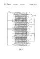
- FIG. 1 is a view illustrating the arrangement of a first embodiment of electrodes in the cell according to the present invention.
- FIG. 2 is a view illustrating the arrangement of a second embodiment of electrodes in the cell according to the present invention.
- FIG. 3 is a view illustrating the arrangement of a third embodiment of electrodes in the cell according to the present invention.
- FIG. 4 is a view illustrating the arrangement of a fourth embodiment of electrodes in the cell according to the present invention.
- FIG. 5 is a view illustrating the arrangement of a fifth embodiment of electrodes in the cell according to the present invention.
- FIG. 6 is a view illustrating the arrangement of a sixth embodiment of electrodes in the cell according to the present invention.
- FIG. 7 is a view illustrating the arrangement of a seventh embodiment of electrodes in the cell according to the present invention.
- FIG. 8 is a view illustrating the arrangement of an eighth embodiment of electrodes in the cell according to the present invention.
- FIG. 9 is a view illustrating the arrangement of a ninth embodiment of electrodes in the cell according to the present invention.
- the active material of negative electrode in the organic electrolytic cell of the present invention may be any one capable of reversibly carrying lithium, and examples thereof include graphite, various carbon materials, polyacene substance, tin oxide, silicon oxide and the like. Among them, it is preferred to use an infusible and insoluble substrate having a polyacene skeletal structure and a hydrogen/carbon atomic ratio of 0.50 to 0.05, the substrate being a heat-treated product of an aromatic condensation polymer, because a high capacity can be obtained.
- the aromatic condensation polymer is a condensate of an aromatic hydrocarbon compound and aldehydes.
- aromatic hydrocarbon compound for example, so-called phenols such as phenol, cresol, xylenol and the like can be suitably used.
- methylenebisphenols represented by the following formula:
- x and y are independently 0, 1 or 2, or hydroxybiphenyls or hydroxynaphthalenes.
- phenols particularly phenol, are preferred.
- aromatic condensation polymer there can also be used a modified aromatic condensation polymer wherein a portion of the aromatic hydrocarbon compound having phenolic hydroxyl groups is replaced with an aromatic hydrocarbon compound having no phenolic hydroxyl group such as xylene, toluene or aniline, for example, a condensate of phenol, xylene and formaldehyde. Furthermore, there can also be used a modified aromatic polymer wherein the above portion is replaced with melamine or urea. A furan resin is also preferred.
- aldehyde it is possible to use aldehydes such as formaldehyde, acetaldehyde and furfural, but formaldehyde is preferred.
- a phenolformaldehyde condensate may be any of a novolak type, a resol type or a mixture thereof.
- the infusible and insoluble substrate can be obtained by a heat treatment of the above aromatic polymer, and includes all of infusible and insoluble substrates having a polyacene skeletal structure described in Japanese Patent Publication Nos. 44212/1989 and 24024/1991.
- the infusible and insoluble substrate used in the present invention can also be produced as follows. That is, an infusible and insoluble substrate having a hydrogen/carbon atomic ratio (hereinafter referred to as H/C) of 0.50 to 0.05, preferably 0.35to 0.10 can be obtained by gradually heating the aromatic condensation polymer up to a proper temperature of 400 to 800° C. in a non-oxidizing atmosphere (including a vacuum).
- H/C hydrogen/carbon atomic ratio
- an infusible and insoluble substrate having a specific surface area, measured by the BET method, of not less than 600 m 2 /g can also be obtained by preparing a solution containing a initial condensate of an aromatic condensation polymer and an inorganic salt such as zinc chloride; heating the solution to cure it in a mold; gradually heating the cured matter in a non-oxidizing atmosphere (including a vacuum) up to a temperature of 350 to 800° C., preferably up to a proper temperature of 400 to 750° C.; and then sufficiently washing it with water, diluted hydrochloric acid or the like.
- the infusible and insoluble substrate has a polyacene skeletal structure wherein an aromatic polycyclic structure is moderately developed, and takes an amorphous structure.
- the substrate can be doped stably with lithium and, therefore, it is useful as an active material for cells.
- this infusible and insoluble substrate has H/C ranging from 0.50 to 0.05.
- H/C exceeds 0.50, the aromatic polycyclic structure does not sufficiently develop, and thus it is impossible to conduct doping and undoping of lithium smoothly, and when a cell is assembled, charge and discharge efficiency is lowered.
- H/C is less than 0.05, the capacity of the cell of the present invention is likely to be lowered.
- the negative electrode in the organic electrolytic cell according to the present invention is composed of the above infusible and insoluble substrate (hereinafter referred to as PAS), and practically, it is preferred to use a form obtained by forming PAS in an easily formable form such as a powdery form, a granular form or a short fiber form with a binder.
- a binder there can be used fluorine-containing resins such as polyethylene tetrafluoride and polyvinylidene fluoride, and thermoplastic resins such as polypropylene and polyethylene. It is preferred to use a fluorine binder.
- F/C fluorine/carbon atomic ratio
- the fluorine binder includes, for example, polyvinylidene fluoride, vinylidene fluoride-ethylene trifluoride copolymer, ethylene-ethylene tetrafluoride copolymer, propylene-ethylene tetrafluoride or the like. Furthermore, it is also possible to use a fluorine-containing polymer wherein hydrogens at the principal chain are replaced with alkyl groups.
- F/C is 1.
- F/C values become 1.25 and 1.10, respectively.
- electrically conductive materials such as acetylene black, graphite, metallic powder and the like may be appropriately added in the negative electrode of the organic electrolytic cell of the present invention.
- the active material of positive electrode in the organic electrolytic cell according to claim 1 of the present invention is not specifically limited, for example there can be used lithium-containing metallic oxides capable of electrochemically doping with lithium and electrochemically undoping lithium, which can be represented by the general formula LixMyOz (M is a metal, or can be two or more metals) such as LixCoO 2 , LixNiO 2 , LixMnO 2 or LixFeO 2 , or oxides of transition metals such as cobalt, manganese and nickel.
- the above electrically conductive polymers such as PAS can also be suitably used.
- a lithium-containing oxide having a voltage of not less than 4 V vs lithium metal is preferred.
- lithium-containing cobalt oxides, lithium-containing nickel oxides or lithium-containing cobalt-nickel double oxides are particularly preferred.
- the active material of positive electrode in the organic electrolytic cell according to claim 4 of the present invention is not specifically limited, for example there can be used lithium-containing metallic oxides capable of reversibly carrying lithium, which can be represented by the general formula LixMyOz (M is a metal, or can be two or more metals) such as LixCoO 2 , LixNiO 2 , LixMnO 2 or LixFeO 2 , or oxides and sulfides of transition metals such as cobalt, manganese, vanadium, titanium and nickel.
- the above electrically conductive polymers such as PAS can be suitably used.
- These active materials of positive electrode can be roughly classified into two kinds.
- an active material of positive electrode (referred to as a first type of an active material of positive electrode in the present invention) capable of emitting lithium through electrochemical oxidation, namely charge, such as lithium-containing cobalt oxides, lithium-containing nickel oxides and lithium-containing cobalt-nickel double oxides, and the other active material of positive electrode (referred to as a second type of an active material of positive electrode in the present invention).
- a lithium-containing oxide having a voltage of not less than 4 V vs lithium metal is preferred.
- lithium-containing cobalt oxides, lithium-containing nickel oxides or lithium-containing cobalt-nickel double oxides are particularly preferred.
- the positive electrode in the organic electrolytic cell of the present invention is one made by optionally adding an electrically conductive material and a binder to the above each active material and molding the mixture, and the kind and composition of the electrically conductive material and binder can be appropriately specified.
- the electrically conductive material a powder of a metal such as metallic nickel can be used.
- Carbon material such as active carbon, carbon black, acetylene black and graphite can be suitably used.
- a mixing ratio of these electrically conductive materials varies depending on the electric conductivity of the active material, shape of the electrode, etc., but it is suitable to add it in an amount of 2 to 40% based on the active material.
- electrolyte to be dissolved in the single or mixed solvent
- any of electrolyte capable of forming lithium ions can be used.
- the electrolyte includes, for example, LiI, LiClO 4 , LiAsF 6 , LiBF 4 , LiPF 6 or the like.
- the electrolyte and solvent are mixed in a state of being sufficiently dehydrated to give an electrolytic solution.
- concentration of the electrolyte in the electrolytic solution it is preferred to make the concentration of the electrolyte in the electrolytic solution at least 0.1 mol/l and it is more preferred to make it 0.2 to 1.5 mol/l.
- the current collector of positive electrode and current collector of negative electrode in the organic electrolytic cell of the present invention are respectively provided with pores piercing from the front surface to the back surface, and are made of materials such as expanded metal, punched metal, net, foamed material or the like.
- the form and number of these through pores are not specifically limited and can be appropriately determined so that lithium ions in the electrolytic solution described hereinafter can transfer between the surface and back surfaces of the electrode without being interrupted by the current collector of electrode.
- the proportion (form and number) of the through pores is determined by the porosity of the electrode-current collector, it is preferred to make the porosity 10% or more, particularly 30% or more.
- the porosity of the electrode current collector is obtained by reducing a ratio of ⁇ 1 ⁇ (weight of current collector/true specific gravity of current collector)/(apparent volume of current collector) ⁇ to percentage.
- the porosity is preferably determined by considering the desired cell characteristics, thickness of the electrode, safety, and kind of the current collector.
- the material of the electrode-current collector there can be used various materials which are generally proposed in lithium cells. Aluminum and stainless steel can be used as the current collector of positive electrode, whereas, stainless steel, copper and nickel can be used as the current collector of negative electrode.
- a material, which does not make an alloy with lithium and has resistance to electrochemical oxidation such as stainless steel.
- lithium originating in the negative electrode is carried by electrochemical contact with lithium arranged to face the negative or positive electrode and the opposed area of said lithium is not more than 40%, preferably not more than 30% of the area of the negative electrode.
- lithium originating in the positive electrode is carried by electrochemical contact with lithium arranged to face the negative or positive electrode and the opposed area of said lithium is not more than 40%, preferably not more than 30% of the area of the positive electrode.
- the term “lithium” used in this specification refer to any material, which contains at least lithium and is capable of supplying lithium ions, such as lithium metal, lithium-aluminum alloy or the like.
- the opposed area of lithium is made 40% or less, preferably 30% or less of the area of negative electrode or area of positive electrode, thereby making it possible to improve the freedom of the cell design and mass-productivity and to afford excellent charge and discharge characteristics. That is, it is very complicated to attach a lithium metal on almost all of the negative or positive electrode, like the above example, and it is not suited for industrial production and it becomes difficult to conduct mass-production.
- the opposed area of lithium exceeds 40% of the area of negative electrode or area of positive electrode, the thickness of the electrode is decided by that of lithium, thereby to cause a problem that desired charge and discharge characteristics can not be obtained.
- the total amount of lithium contained the cell is preferably not less than 500 mAh/g and the amount of lithium originating in the negative electrode is preferably not less than 100 mAh/g, based on the active material of negative electrode.
- the total amount of lithium contained the cell is the total of the amount of lithium originating in the positive electrode, that of lithium originating in the electrolytic solution and that of lithium originating in the negative electrode.
- Lithium originating in the positive electrode is lithium contained in the positive electrode on assembly of the cell, and a portion or all of said lithium is supplied to the negative electrode through an operation of applying a current from an external circuit (charge).
- lithium originating in the positive electrode is lithium contained in the positive electrode and at least one portion, namely a portion or all of lithium is carried by electrochemical contact with lithium arranged to face the negative or positive electrode.
- LiCoO 2 as the active material of positive electrode
- LiCoO 2 has already contained lithium on assembly of the cell, but lithium originating in the positive electrode is obtained by further adding lithium carried through electrochemical contact with lithium.
- V 2 O 5 as the active material of positive electrode, since this material does not contain lithium, all of lithium originating in the positive electrode is carried by electrochemical contact with lithium.
- At least one portion, namely portion or all of this lithium originating in the positive electrode is supplied to the negative electrode through an operation of applying a current from an external circuit (charge). Then, the electrochemical contact between lithium and the positive electrode initiates when the electrolytic solution is poured into the cell system.
- the above first type of an active material of positive electrode since said active material of positive electrode has already contained releasable lithium, it becomes possible to charge the cell system immediately after pouring the electrolytic solution into the cell system.
- the second type of an active material of positive electrode it is possible to charge the cell system before all lithium is completely charged on the active material of positive electrode after pouring the electrolytic solution into the cell system.
- the above charge operation is effective to reduce the carrying time and to prevent the positive electrode from being in an over-discharge state, thereby preventing deterioration of the positive electrode due to the carrying operation of lithium.
- Lithium originating in the electrolytic solution in the organic electrolytic cell of the present invention is lithium in the electrolytic solution contained in the separator, positive electrode and negative electrode, whereas, lithium originating in the negative electrode is lithium carried on the active material of negative electrode and is lithium other than lithium originating in the positive electrode and lithium originating in electrolytic solution.
- FIG. 1 to FIG. 6 respectively illustrate the embodiment of a cell of the type wherein plural pairs of positive electrode plates, a separator and a negative electrode plate are laminated in sequence in the organic electrolytic cell of the present invention.
- FIG. 1 illustrates one embodiment of the arrangement of electrodes in a casing of the cell of the above type.
- a negative electrode 2 molded on both surfaces of a current collector 2 ′ of negative electrode and a lithium metal 4 contact-bonded on a lithium metal current collector 4 ′ made of a stainless mesh or a copper expanded metal, which is arranged at the lower portion of a multi-layer unit, are connected through a conductor 5 .
- a positive electrode 1 molded on both surfaces of a current collector 1 ′ of positive electrode is laminated via the above negative electrode 2 and separator 3 , and is connected through a conductor 5 ′.
- the above current collector 2 ′ of negative electrode and lithium metal current collector 4 ′ can also be welded directly.
- FIG. 3 Another modified embodiment shown in FIG. 3 illustrates that the lithium metal 4 is arranged in the center of the multi-layer unit.
- FIG. 4 illustrates another embodiment of the arrangement of electrodes of the above type.
- the positive electrode 1 molded on both surfaces of the current collector 1 ′ of positive electrode and the lithium metal 4 contact-bonded on the lithium metal current collector 4 ′ made of a stainless mesh or a copper expanded metal, which is arranged at the lower portion of the multi-layer unit, are connected through the conductor 5 ′.
- the negative electrode 2 molded on both surfaces of the current collector 2 ′ of negative electrode is laminated via the above positive electrode 1 and separator 3 , and is connected through the conductor 5 .
- the above current collector 1 ′ of positive electrode and lithium metal current collector 4 ′ can also be welded directly.
- FIG. 5 illustrates a modified embodiment of the arrangement of electrodes shown in FIG. 4 .
- the lithium metal 4 contact-bonded on the lithium metal current collector 4 ′ is arranged at the upper and lower portions of the multi-layer unit, respectively.
- FIG. 6 Another modified embodiment shown in FIG. 6 illustrates that the lithium metal 4 is arranged in the center of the multi-layer unit.
- the current corrector 1 ′ of positive electrode and current corrector 2 ′ of negative electrode are respectively provided with pores (shown on FIGS. 1 and 4) piercing from the front surface to the back surface, and a terminal of positive electrode and a terminal of negative electrode of the cell are connected with them, respectively.
- the current collector 1 ′ of positive electrode can be directly welded without providing the conductor 5 ′.
- the current collector 2 ′ of negative electrode can be directly welded without providing the conductor 5 .
- the position of the lithium metal 4 to be arranged can be appropriately changed as shown in the above embodiments.
- FIG. 7 to FIG. 9 respectively illustrate the embodiment of the arrangement of electrodes of a cell having a wound-type structure used in a cylindrical cell as the embodiment of the present invention.
- a positive electrode 1 and a negative electrode 2 are molded on a current collector, respectively (in the drawing, the current collector is eliminated).
- FIG. 7 illustrates the embodiment wherein the lithium metal 4 is attached on the current collector of an outer-most negative electrode 2 (in the drawing, only the lithium metal 4 is shown at the portion where the lithium metal is laminated)
- FIG. 8 illustrates the embodiment wherein the lithium metal 4 is attached on the current collector of an outer-most positive electrode 1 (in the drawing, only the lithium metal 4 is shown at the portion where the lithium metal is laminated).
- FIG. 9 illustrates the embodiment wherein the lithium metal 4 having a columnar shape is arranged in the center of a wound-type structure.
- the separator 3 is made of a porous material, which is durable against the electrolytic solution or the electrode active material and which has open pores and is electrically non-conductive.
- a cloth, non-woven fabric or porous material made of glass fiber, polyethylene or polypropylene.
- the separator 3 is preferably as thin as possible. Its thickness, however, is determined by appropriately considering the amount of electrolytic solution held, permeability, strength or the like.
- the separator 3 is impregnated with the electrolytic solution, and in the electrolytic solution, the above compound capable of forming lithium ions with which doping is made is dissolved in an aprotic organic solvent.
- the electrolytic solution is usually a liquid and impregnated into the separator 3 , but it can also be used, without any separator 3 , after being made into gel or a solid for preventing leakage of the solution.
- the negative or positive electrode is made contact with lithium (lithium metal in these embodiments) via the conductor 5 or 5 ′ made of nickel, copper or stainless steel, or attaching lithium on the current collector of negative electrode or the current collector of positive electrode, but the organic electrolytic cell of the present invention is not specifically limited to this structure.
- lithium may also be made contact by directly attaching it on the negative or positive electrode, or by directly attaching it on a negative electrode case or a positive electrode case. That is, it is necessary to arrange so that, when the electrolytic solution is poured on assembly of the cell, any of the negative or positive electrode is electrochemically made contact with lithium thereby to carry lithium on an active material of negative electrode or an active material of positive electrode and the active material of negative electrode via the electrolytic solution.
- the amount of lithium originating in the negative electrode or lithium originating in the positive electrode can be appropriately determined by the desired cell, active material of negative electrode or active material of positive electrode, but a particularly high-capacity cell can be obtained by using PAS as the active material of negative electrode and satisfying the following conditions. That is, when using PAS as the active material of negative electrode, the total amount of lithium in the cell is preferably not less than 500 mAh/g, more preferably not less than 600 mAh/g, based on PAS of negative electrode so as to obtain a sufficient capacity.
- the amount of lithium originating in the negative electrode is preferably not less than 100 mAh/g, more preferably not less than 150 mAh/g, based on PAS of negative electrode.
- the amount of lithium originating in the negative electrode is less than 100 mAh/g even if the total amount of lithium is not less than 500 mAh/g based on PAS of negative electrode, there is some possibility of causing a problem that a sufficient capacity can not be obtained.
- a lithium-containing metal oxide as the positive electrode a high capacity can be obtained by adjusting the amount of lithium originating in the negative electrode to 600 mAh/g or less based on PAS of negative electrode, which is preferred.
- the amount of lithium originating in the positive electrode and that of lithium originating in the electrolytic solution can be appropriately determined, the amount of lithium originating in the positive electrode is preferably not less than 300 mAh/g based on PAS of negative electrode so as to obtain a high capacity when using a lithium-containing metal oxide as the positive electrode.
- lithium originating in the positive electrode is preferably carried in the amount of not less than 100 mAh/g, more preferably not less than 150 mAh/g, based on PAS of negative electrode, in addition to lithium contained intrinsically in the positive electrode so as to obtain a high capability.
- lithium originating in the negative electrode may be previously carried on PAS as the active material of negative electrode.
- the above second type of an active material of positive electrode since the amount of lithium to be carried increases, it is effective to separately carry a required amount of lithium on the negative or positive electrode so as to reduce the carrying time.
- the shape of the organic electrolytic cell according to the present invention includes, for example, cylindrical shape, rectangular shape and box shape, but is not specifically limited.
- a phenol-formaldehyde resin having a thickness of 0.5 mm was put in a silicon carbide heating elements, and heat-treated by heating to 500° C. under a nitrogen atmosphere at a rate of 50° C./hour and then heating to 650° C. at a rate of 10° C./hour, thereby to synthesize PAS.
- the PAS plate thus obtained was ground by using a disc mill to obtain PAS powder having an average particle diameter of about 7 ⁇ m.
- the H/C ratio of this PAS powder was 0.22.
- LiCoO 2 first type of positive electrode
- graphite graphite
- a solution of 3.5 parts by weight of polyvinylidene fluoride powder in 50 parts by weight of N-methyl pyrrolidone to obtain a slurry.
- the slurry was molded on both surfaces of an aluminum expanded metal having a thickness of 240 ⁇ m (porosity: 88%) (manufactured by Sank Co., LW: 2 mm, SW: 1 mm) to obtain a positive electrode having a thickness of 780 ⁇ m.
- the negative electrodes (one surface ⁇ 2, both surfaces ⁇ 3) were respectively made contact with the stainless steel net, on which lithium was contact-bonded, through welding.
- the amount of lithium metal was about 250 mAh/g based on the negative electrode PAS.
- As the electrolytic solution a solution of LiPF 6 at a concentration of 1 mol/l in a 1:1 (volume ratio) mixed solution of ethylene carbonate and diethyl carbonate was used.
- the total amount of lithium contained in the cell was 1500 mAh/g based on the negative electrode PAS.
- One cell was allowed to stand at room temperature for two days, and then decomposed. As a result, lithium metal completely disappeared.
- each of the above cells was charged at 4.2V for 12 hours at the maximum current of 150 mA. Subsequently, each of the above cells was discharged at a constant current of 70 mA until the cell voltage became 2.0 V. This 4.2 V-2.0 V cycle was repeated, and in the third discharge, the cell capacity was evaluated. As a result, it was 720 mAh. In the fourth cycle, discharge at constant current of 350 mA was conducted and the cell capacity was evaluated. As a result, it was 300 mAh.
- a PAS negative electrode having a thickness of 182 ⁇ m and a positive electrode having a thickness of 271 ⁇ m were obtained.
- the positive electrode (2.0 ⁇ 3.0 cm 2 ) PAS negative electrode (2.2 ⁇ 3.2 cm 2 ) and a polypropylene separator having a thickness of 25 ⁇ m, two cells wherein the positive electrode, separator and negative electrode (nine positive electrodes) are laminated shown in FIG. 1 were assembled.
- two outer negative electrodes one having a thickness of 130 ⁇ m obtained by peeling off one of the above negative electrodes molded on both surfaces was used.
- the lithium metal one obtained by contact-bonding a lithium metallic foil (289 ⁇ m, 2.2 ⁇ 3.2 cm 2 ) on a stainless steel net having a thickness of 80 ⁇ m was used and was arranged to face the negative electrode.
- the negative electrodes (one surface ⁇ 2, both surfaces ⁇ 8) were respectively made contact with the stainless steel net, on which lithium was contact-bonded, through welding.
- the amount of lithium metal was about 250 mAh/g based on the negative electrode PAS.
- the total thickness of the electrode, separator and lithium metal was almost the same as in Example 1.
- the electrolytic solution was the same as in Example 1.
- the total amount of lithium contained in the cell was 1500 mAh/g based on the negative electrode PAS.
- One cell was allowed to stand at room temperature for two days, and then decomposed. As a result, lithium metal completely disappeared.
- each of the above cells was charged at 4. 2V for 12 hours at the maximum current of 150 mA. Subsequently, each of the above cells was discharged at a constant current of 70 mA until the cell voltage became 2.0 V. This 4.2 V-2.0 V cycle was repeated, and in the third discharge, the cell capacity was evaluated. As a result, it was 650 mAh. In the fourth cycle, discharge at constant current of 350 mA was conducted and the cell capacity was evaluated. As a result, it was 620 mAh.
- Example 2 Two cells wherein the positive electrode, separator and negative electrode (nine positive electrodes) are laminated shown in FIG. 1 were assembled.
- As two outer negative electrodes one having a thickness of 130 ⁇ m obtained by peeling off one of the above negative electrodes molded on both surfaces was used.
- As the lithium metal one obtained by contact-bonding a lithium metallic foil (100 ⁇ m, 2.2 ⁇ 3.2 cm 2 ) on a stainless steel net having a thickness of 80 ⁇ m was used and two plates were arranged at the upper and lower portions of an electrode multi-layer unit so as to face the negative electrode.
- the negative electrodes (one surface ⁇ 2, both surfaces ⁇ 8) were respectively made contact with the stainless steel net, on which lithium was contact-bonded, through welding.
- the amount of lithium metal was about 250 mAh/g based on the negative electrode PAS.
- the total thickness of the electrode, separator and lithium metal was almost the same as in Example 1.
- the electrolytic solution was the same as in Example 1.
- the total amount of lithium contained in the cell was 1500 mAh/g based on the negative plate PAS.
- One cell was allowed to stand at room temperature for two days, and then decomposed. As a result, lithium metal completely disappeared.
- each of the above cells was charged at 4. 2V for 12hours at the maximum current of 150 mA.Subsequently, each of the above cells was discharged at a constant current of 70 mA until the cell voltage became 2.0 V. This 4.2 V-2.0 V cycle was repeated, and in the third discharge, the cell capacity was evaluated. As a result, it was 650 mAh. In the fourth cycle, discharge at constant current of 350 mA was conducted and the cell capacity was evaluated. As a result, it was 620 mAh.
- Example 1 The slurry obtained in Example 1 was molded on one surface of an aluminum expanded metal having a thickness of 120 ⁇ m (porosity: 85%) (manufactured by Sank Co., LW: 2 mm, SW: 1 mm) to obtain a positive electrode having a thickness of 400 ⁇ m.
- the amount of lithium metal was about 250 mAh/g based on the negative electrode PAS.
- the electrolytic solution was the same as in the above respective Examples.
- the total amount of lithium contained in the cell was 1500 mAh/g based on the negative plate PAS.
- each of the cells was charged at a constant current of 150 mA for 4 hours. Then, one cell was allowed to stand at room temperature for two days and decomposed. As a result, lithium metal completely disappeared.
- each of the above cells was charged at 4. 2V for 12 hours at the maximum current of 150 mA. Subsequently, each of the above cells was discharged at a constant current of 70 mA until the cell voltage became 2.0 V. This 4.2 V-2.0 V cycle was repeated, and in the third discharge, the cell capacity was evaluated. As a result, it was 720 mAh. In the fourth cycle, discharge at constant current of 350 mA was conducted and the cell capacity was evaluated. As a result, it was 300 mAh.
- Example 4 Two cells wherein the positive electrode, separator and negative electrode (nine negative electrodes) are laminated shown in FIG. 4 were assembled.
- the lithium metal one obtained by contact-bonding a lithium metallic foil (230 ⁇ m, 2.0 ⁇ 3.0 cm 2 ) on a stainless steel net having a thickness of 80 ⁇ m was used and arranged to face the positive electrode.
- the positive electrodes (one surface ⁇ 2, both surfaces ⁇ 8) were respectively made contact with the stainless steel net, on which lithium was contact-bonded, through welding.
- the amount of lithium metal was about 250 mAh/g based on the negative electrode PAS.
- the total thickness of the electrode, separator and lithium metal was almost the same as in Example 4.
- the electrolytic solution was the same as in the above respective Examples.
- the total amount of lithium contained in the cell was 1500 mAh/g based on the negative plate PAS.
- each of the cells was charged at a constant current of 150 mA for 4 hours. Then, one cell was allowed to stand at room temperature for two days and decomposed. As a result, lithium metal completely disappeared.
- Each of the above cells was discharged at a constant current of 70 mA until the cell voltage became 2.0 V, and charged at 4.2V for 12 hours at the maximum current of 150 mA. Subsequently, each of the above cells was discharged at a constant current of 70 mA until the cell voltage became 2.0 V. This 4.2 V-2.0 V cycle was repeated, and in the third discharge, the cell capacity was evaluated. As a result, it was 650 mAh. In the fourth cycle, discharge at constant current of 350 mA was conducted and the cell capacity was evaluated. As a result, it was 620 mAh.
- Example 5 Two cells wherein the positive electrode, separator and negative electrode (nine negative electrodes) are laminated shown in FIG. 5 were assembled.
- Two outer positive electrodes were the same as in Example 5.
- the lithium metal one obtained by contact-bonding a lithium metallic foil (120 ⁇ m, 2.0 ⁇ 3.0 cm 2 ) on a stainless steel net having a thickness of 80 ⁇ m was used and arranged to face the positive electrode.
- the positive electrodes (one surface ⁇ 2, both surfaces ⁇ 8) were respectively made contact with the stainless steel net, on which lithium was contact-bonded, through welding.
- the amount of lithium metal was about 250 mAh/g based on the negative electrode PAS.
- the total thickness of the electrode, separator and lithium metal was almost the same as in Example 4.
- the electrolytic solution was the same as in the above respective Examples.
- the total amount of lithium contained in the cell was 1500 mAh/g based on the negative electrode PAS.
- each of the cells was charged at a constant current of 150 mA for 4 hours. Then, one cell was allowed to stand at room temperature for two days and decomposed. As a result, lithium metal completely disappeared.
- Each of the above cells was discharged at a constant current of 70 mA until the cell voltage became 2.0 V, and charged at 4.2V for 12 hours at the maximum current of 150 mA. Subsequently, each of the above cells was discharged at a constant current of 70 mA until the cell voltage became 2.0 V. This 4.2 V-2.0 V cycle was repeated, and in the third discharge, the cell capacity was evaluated. As a result, it was 650 mAh. In the fourth cycle, discharge at constant current of 350 mA was conducted and the cell capacity was evaluated. As a result, it was 620 mAh.
- a PAS negative electrode having a thickness of 290 ⁇ m and a positive electrode having a thickness of 438 ⁇ m were obtained.
- the positive electrode (2.0 ⁇ 3.0 cm 2 ) PAS negative electrode (2.2 ⁇ 3.2 cm 2 ) and polypropylene separator having a thickness of 25 ⁇ m, two cells wherein the positive electrode, separator and negative electrode (seven positive electrodes) are laminated were assembled.
- two outer negative electrodes one having a thickness of 175 nm obtained by peeling off one of the above negative electrodes molded on both surfaces was used.
- lithium metal As the lithium metal, a lithium metallic foil (33 ⁇ m, 2.2 ⁇ 3.2 cm 2 , 1.6 ⁇ 2.2 cm 2 for outer two foils) was attached to the negative electrode plate.
- the amount of lithium metal was about 250 mAh/g based on the negative electrode PAS.
- the total thickness of the electrode, separator and lithium metal was almost the same as in Example 1.
- the electrolytic solution was the same as in Example 1.
- the total amount of lithium contained in the cell was 1500 mAh/g based on the negative plate PAS.
- One cell was allowed to stand at room temperature for two days, and then decomposed. As a result, lithium metal completely disappeared.
- each of the above cells was charged at 4.2V for 12 hours at the maximum current of 150 mA.Subsequently, each of the above cells was discharged at a constant current of 70 mA until the cell voltage became 2.0 V. This 4.2 V-2.0 V cycle was repeated, and in the third discharge, the cell capacity was evaluated. As a result, it was 680 mAh. In the fourth cycle, discharge at constant current of 350 mA was conducted and the cell capacity was evaluated. As a result, it was 400 mAh.
- Example 2 In the same manner as in Example 1, a PAS negative electrode having a thickness of 250 ⁇ m and a positive electrode having a thickness of 380 ⁇ m were obtained. Using the positive electrode (2.0 ⁇ 3.0 cm 2 ), PAS negative electrode (2.2 ⁇ 3.2 cm 2 ) and a polypropylene separator having a thickness of 25 ⁇ m, two cells wherein the positive electrode, separator and negative electrode (seven negative electrodes) are laminated were assembled. As two outer positive electrodes, one having a thickness of 190 ⁇ m obtained by molding the slurry on one surface of an aluminum expanded metal having a thickness of 120 ⁇ m in the same manner as in Example 4 was used.
- lithium metal As the lithium metal, a lithium metallic foil (33 ⁇ m, 2.0 ⁇ 3.0 cm 2 , 1.5 ⁇ 2.0 cm 2 for outer two foils) was attached to the positive electrode plate.
- the amount of lithium metal was about 250 mAh/g based on the negative electrode PAS.
- the total thickness of the electrode, separator and lithium metal was almost the same as in the above respective Examples.
- the electrolytic solution was the same as in Example 1.
- the total amount of lithium contained in the cell was 1500 mAh/g based on the negative plate PAS.
- each of the cells was charged at a constant current of 150 mA for 4 hours. Then, one cell was allowed to stand at room temperature for two days and decomposed. As a result, lithium metal completely disappeared.
- Each of the above cells was discharged at a constant current of 70 mA until the cell voltage became 2.0 V, and charged at 4.2V for 12 hours at the maximum current of 150 mA. Subsequently, each of the above cells was discharged at a constant current of 70 mA until the cell voltage became 2.0 V. This 4.2 V-2.0 V cycle was repeated, and in the third discharge, the cell capacity was evaluated. As a result, it was 550 mAh. In the fourth cycle, discharge at constant current of 350 mA was conducted and the cell capacity was evaluated. As a result, it was 320 mAh.
- Comparative Examples 4 and 5 although the thickness of lithium may be reduced to improve the charge and discharge characteristics, it is very complicated method, which is not suited for industrial production, to attach a lithium foil having a thickness of about 30 ⁇ m as a lower limit of the thickness for mass-production of lithium on each one negative electrode, actually. That is, in order to reduce the thickness of the electrode so as to improve the charge and discharge characteristics, a further thin lithium foil is required, whereby it becomes more difficult to conduct mass production and it becomes unsuitable for practical use.
- the present invention can provide a method of carrying a lithium negative electrode or lithium positive electrode having a very large freedom considering the charge and discharge characteristics in a cell system having lithium originating in the negative electrode, namely cell system wherein lithium is previously carried on the negative electrode, or a cell system wherein lithium is previously carried on the positive electrode in addition to lithium contained intrinsically in the positive electrode.
- a PAS negative electrode having a thickness of 180 ⁇ m and a positive electrode having a thickness of 290 ⁇ m were obtained.
- the positive electrode 5.4 cm in width ⁇ 37.0 cm in length
- PAS negative electrode 5.6 cm in width ⁇ 39.0 cm in length
- polypropylene separator having a thickness of 25 ⁇ m
- two cells were assembled.
- a current collector portion 4.8 cm capable of forming no active material of negative electrode (total length of the negative electrode is 3.9 cm+4.8 cm).
- each of the above cells was charged at 4.2V for 12 hours at the maximum current of 500 mA.Subsequently, each of the above cells was discharged at a constant current of 200 mA until the cell voltage became 2.0 V. This 4.2 V-2.0 V cycle was repeated, and in the third discharge, the cell capacity was evaluated. As a result, it was 2000 mAh. In the fourth cycle, discharge at constant current of 1000 mA was conducted and the cell capacity was evaluated. As a result, it was 1900 mAh. The energy density was calculated. As a result, it was large such as 390 Wh/l.
- Each of the above cells was discharged at a constant current of 200 mA until the cell voltage became 2.0 V, and charged at a constant current of 500 mA until the cell voltage became 4.2 V, and then constant current/constant voltage charge of applying a constant voltage of 4.2 V was conducted for 12 hours. Subsequently, each of the above cells was discharged at a constant current of 200 mA until the cell voltage became 2.0 V. This 4.2 V-2.0 V cycle was repeated, and in the third discharge, the cell capacity was evaluated. As a result, it was 1980 mAh. In the fourth cycle, discharge at constant current of 1000 mA was conducted and the cell capacity was evaluated. As a result, it was 1850 mAh. The energy density was calculated. As a result, it was large such as 385 Wh/l.
- Example 7 In the same manner as in Example 7, a PAS negative electrode having a thickness of 180 ⁇ m and a positive electrode having a thickness of 290 ⁇ m were obtained. Using the positive electrode (5.4 cm in width ⁇ 37.5 cm in length), PAS negative electrode (5.6 cm in width ⁇ 39.5 cm in length) and polypropylene separator having a thickness of 25 ⁇ m, two cylindrical cells were assembled. Lithium was not arranged in the cell. The electrolytic solution was the same as in the above respective Examples. The total amount of lithium contained in the cell was 1250 mAh/g based on the negative plate PAS.
- each of the above cells was charged at 4.2V for 12 hours at the maximum current of 500 mA.Subsequently, each of the above cells was discharged at a constant current of 200 mA until the cell voltage became 2.0 V. This 4.2 V-2.0 V cycle was repeated, and in the third discharge, the cell capacity was evaluated. As a result, it was 1500 mAh. In the fourth cycle, discharge at constant current of 1000 mA was conducted and the cell capacity was evaluated. As a result, it was 1450 mAh. The energy density was calculated. As a result, it was large such as 290 Wh/l.
- a PAS negative electrode having a thickness of 200 ⁇ m was obtained. Then, 100 parts by weight of V 2 O 5 (second type of the positive electrode) and 10 parts by weight of acetylene black were sufficiently mixed with a solution of 3.5 parts by weight of polyvinylidene fluoride powder in 80 parts by weight of N-methyl pyrrolidone to obtain a slurry. The slurry was molded on both surfaces of an aluminum expanded metal having a thickness of 240 ⁇ m (porosity: 88%) (manufactured by Sank Co., LW: 2 mm, SW: 1 mm) to obtain a positive electrode having a thickness of 750 ⁇ m.
- a slurry was molded on one surface of an aluminum expanded metal having a thickness of 120 ⁇ m (porosity: 85%) (manufactured by Sank Co., LW: 2mm, SW: 1 mm) to obtain a positive electrode having a thickness of 300 ⁇ m.
- the positive electrodes (one surface ⁇ 2, both surfaces ⁇ 8) were respectively made contact with the stainless steel net, on which lithium was contact-bonded, through welding.
- the amount of lithium metal was about 1000 mAh/g based on the negative electrode PAS.
- the electrolytic solution was the same as in Example 1.
- the total amount of lithium contained in the cell was 1500 mAh/g based on the negative plate PAS.
- One cell was allowed to stand at room temperature for seven days, and then decomposed. As a result, lithium metal completely disappeared.
- Each of the above cells was charged at 3.3 V for 12 hours at the maximum current of 150 mA.
- each of the above cells was discharged at a constant current of 70 mA until the cell voltage became 1.0 V.
- This 3.3 V-1.0 V cycle was repeated, and in the third discharge, the cell capacity was evaluated. As a result, it was 600 mAh.
- the organic electrolytic cell according to the present invention is extremely useful because of its easy production, high capacity and high voltage, excellent charge and discharge characteristics, and high safety.
Abstract
Description

Claims (5)
Applications Claiming Priority (5)
| Application Number | Priority Date | Filing Date | Title |
|---|---|---|---|
| JP9-028563 | 1997-01-27 | ||
| JP2856397 | 1997-01-27 | ||
| JP2974397 | 1997-01-28 | ||
| JP9-029743 | 1997-01-28 | ||
| PCT/JP1998/000187 WO1998033227A1 (en) | 1997-01-27 | 1998-01-20 | Organic electrolytic battery |
Publications (1)
| Publication Number | Publication Date |
|---|---|
| US6461769B1 true US6461769B1 (en) | 2002-10-08 |
Family
ID=26366695
Family Applications (1)
| Application Number | Title | Priority Date | Filing Date |
|---|---|---|---|
| US09/355,164 Expired - Lifetime US6461769B1 (en) | 1997-01-27 | 1998-01-20 | Organic electrolytic cell |
Country Status (9)
| Country | Link |
|---|---|
| US (1) | US6461769B1 (en) |
| EP (1) | EP0964468B1 (en) |
| JP (1) | JP3485935B2 (en) |
| KR (1) | KR100381526B1 (en) |
| CN (1) | CN100380726C (en) |
| AU (1) | AU5497898A (en) |
| CA (1) | CA2279864C (en) |
| DE (2) | DE964468T1 (en) |
| WO (1) | WO1998033227A1 (en) |
Cited By (36)
| Publication number | Priority date | Publication date | Assignee | Title |
|---|---|---|---|---|
| US20020160267A1 (en) * | 2001-02-27 | 2002-10-31 | Yasuhiko Ikeda | Rectangular alkaline storage battery |
| US6740454B1 (en) * | 1998-07-27 | 2004-05-25 | Kanebo Limited | Organic electrolytic cell with a porous current collector |
| US20060057433A1 (en) * | 2002-12-26 | 2006-03-16 | Fuji Jukogyo Kabushiki Kaisha | Electrical storage device and manufacturing electrical storage device |
| US20060115723A1 (en) * | 2002-12-25 | 2006-06-01 | Fuji Jukogyo Kabushiki Kaisha | Storage device |
| US20070002524A1 (en) * | 2003-09-30 | 2007-01-04 | Fuji Jukogyo Kabushiki Kaisha | Organic electrolyte capacitor |
| US20070205509A1 (en) * | 2006-02-22 | 2007-09-06 | Samsung Electronics Co., Ltd. | Semiconductor device with battery |
| US20080055819A1 (en) * | 2006-09-04 | 2008-03-06 | Fuji Jukogyo Kabushiki Kaisha | Lithium-ion capacitor |
| US20080094778A1 (en) * | 2006-10-20 | 2008-04-24 | Fuji Jukogyo Kabushiki Kaisha | Lithium-ion capacitor |
| US20080165471A1 (en) * | 2004-03-31 | 2008-07-10 | Fuji Jukogyo Kabushiki Kaisha | Organic Electrolyte Capacitor Using a Mesopore Carbon Material as a Negative Electrode |
| US20090027831A1 (en) * | 2005-03-31 | 2009-01-29 | Fuji Jukogyo Kabushiki Kaisha | Lithium Ion Capacitor |
| US20090135549A1 (en) * | 2005-12-28 | 2009-05-28 | Fuji Jukogyo Kabushiki Kaisha | Lithium ion capacitor |
| US20090147442A1 (en) * | 2007-12-06 | 2009-06-11 | Mitsubishi Electric Corporation | Electric double-layer capacitor and method of producing same |
| US20090174986A1 (en) * | 2005-03-31 | 2009-07-09 | Fuji Jukogyo Kabushiki Kaisha | Lithium ion capacitor |
| US20090246626A1 (en) * | 2005-12-22 | 2009-10-01 | Fuji Jukogyo Kabushiki Kaisha | Lithium metal foil for battery or capacitor |
| US20090246629A1 (en) * | 2008-03-28 | 2009-10-01 | Fuji Jukogyo Kabushiki Kaisha | Manufacturing method of electrode, electric storage device, and intermediate laminate member |
| US20090242507A1 (en) * | 2008-03-26 | 2009-10-01 | Fuji Jukogyo Kabushiki Kaisha | Manufacturing process of electrode |
| US20090262485A1 (en) * | 2005-11-14 | 2009-10-22 | Motohiro Sakata | Electric double layer capacitor |
| US20100033898A1 (en) * | 2006-10-17 | 2010-02-11 | Maxwell Technologies, Inc. | Electrode for energy storage device |
| US7733629B2 (en) | 2005-03-31 | 2010-06-08 | Fuji Jukogyo Kabushiki Kaisha | Lithium ion capacitor |
| CN101819880A (en) * | 2009-02-27 | 2010-09-01 | 富士重工业株式会社 | Wound-type electric storage device |
| US20110236763A1 (en) * | 2010-03-24 | 2011-09-29 | Fuji Jukogyo Kabushiki Kaisha | Electric storage device |
| US20110256438A1 (en) * | 2008-12-26 | 2011-10-20 | Jm Energy Corporation | Wound-type accumulator |
| US20120002348A1 (en) * | 2010-06-30 | 2012-01-05 | Semiconductor Energy Laboratory Co., Ltd. | Electric double layer capacitor, lithium ion capacitor and manufacturing method thereof |
| US20120081839A1 (en) * | 2010-10-01 | 2012-04-05 | Shin-Kobe Electric Machinery Co., Ltd. | Lithium Ion Storage Device |
| US8232009B2 (en) | 2008-08-06 | 2012-07-31 | Fuji Jukogyo Kabushiki Kaisha | Electric storage device |
| US20120236466A1 (en) * | 2011-03-17 | 2012-09-20 | Shin-Kobe Electric Machinery Co., Ltd. | Lithium Ion Capacitor and Layered Member for Lithium Ion Capacitor |
| US20120273255A1 (en) * | 2011-04-26 | 2012-11-01 | Tyco Electronics Corporation | Electrical Conductors Having Organic Compound Coatings |
| US9147876B2 (en) | 2010-08-11 | 2015-09-29 | Kri, Inc. | Method for lithium predoping, method for producing electrodes, and electric energy storage device using these methods |
| US9424996B2 (en) | 2012-05-18 | 2016-08-23 | Jsr Corporation | Electrode active material, electrode and electrical storage device |
| US9461341B2 (en) | 2012-12-26 | 2016-10-04 | Semiconductor Energy Laboratory Co., Ltd. | Power storage device and method for charging the same |
| US9548165B2 (en) | 2012-05-09 | 2017-01-17 | Shin-Etsu Chemical Co., Ltd. | Predoping method for lithium, lithium-predoped electrode, and electricity storage device |
| US9705154B2 (en) | 2013-03-11 | 2017-07-11 | Lg Chem, Ltd. | Method for prelithiation, method for fabricating lithium secondary battery comprising the method, and lithium secondary battery fabricated from the fabricating method |
| US9941506B2 (en) | 2014-02-21 | 2018-04-10 | Semiconductor Energy Laboratory Co., Ltd. | Current collector, secondary battery, electronic device, and manufacturing method thereof |
| US10081547B2 (en) | 2014-09-01 | 2018-09-25 | Jsr Corporation | Electrode material, electrode and electrical storage device |
| US10276887B2 (en) * | 2014-01-06 | 2019-04-30 | Lg Chem, Ltd. | Flexible battery cell |
| US10367194B2 (en) | 2014-10-24 | 2019-07-30 | Semiconductor Energy Laboratory Co., Ltd. | Secondary battery and manufacturing method of the same |
Families Citing this family (20)
| Publication number | Priority date | Publication date | Assignee | Title |
|---|---|---|---|---|
| US6757836B1 (en) | 2000-01-10 | 2004-06-29 | Sun Microsystems, Inc. | Method and apparatus for resolving partial connectivity in a clustered computing system |
| US6769008B1 (en) | 2000-01-10 | 2004-07-27 | Sun Microsystems, Inc. | Method and apparatus for dynamically altering configurations of clustered computer systems |
| CA2451634C (en) * | 2001-06-29 | 2009-06-30 | Kanebo, Limited | Organic electrolytic capacitor |
| US7385801B2 (en) | 2003-03-31 | 2008-06-10 | Fuji Jukogyo Kabushiki Kaisha | Organic electrolyte capacitor |
| JP4738042B2 (en) * | 2005-03-31 | 2011-08-03 | 旭化成株式会社 | Non-aqueous lithium storage element and method for manufacturing the same |
| JP5322435B2 (en) | 2005-04-26 | 2013-10-23 | 富士重工業株式会社 | Negative electrode active material for electricity storage devices |
| JP2007067097A (en) * | 2005-08-30 | 2007-03-15 | Fuji Heavy Ind Ltd | Wound type lithium ion capacitor |
| KR100990467B1 (en) | 2005-08-30 | 2010-10-29 | 후지 주코교 카부시키카이샤 | Lithium ion capacitor |
| JP4924966B2 (en) | 2005-10-17 | 2012-04-25 | 富士重工業株式会社 | Lithium ion capacitor |
| JP4813152B2 (en) | 2005-11-14 | 2011-11-09 | 富士重工業株式会社 | Lithium ion capacitor |
| JP2008123826A (en) * | 2006-11-10 | 2008-05-29 | Fuji Heavy Ind Ltd | Power storage device |
| JP5214199B2 (en) * | 2007-09-18 | 2013-06-19 | 富士重工業株式会社 | Electricity storage device |
| JP5287317B2 (en) * | 2009-02-10 | 2013-09-11 | 新神戸電機株式会社 | Lithium ion capacitor |
| TWI425703B (en) * | 2009-05-26 | 2014-02-01 | Lg Chemical Ltd | Lithium secondary battery with high energy density |
| US9030804B2 (en) | 2009-12-28 | 2015-05-12 | Jm Energy Corporation | Accumulator device |
| WO2013146464A1 (en) * | 2012-03-29 | 2013-10-03 | 住友電気工業株式会社 | Electrode material, and capacitor and secondary battery using said electrode material |
| CN103915262B (en) * | 2013-01-04 | 2017-08-11 | 深圳清华大学研究院 | The method of the pre- embedding lithium of lithium-ion capacitor negative pole |
| EP2980817B1 (en) | 2013-03-25 | 2019-12-25 | JSR Corporation | Electrode active material, electrode, and electricity-storage device |
| CN104037458B (en) * | 2014-05-16 | 2017-02-22 | 中国科学院电工研究所 | Manufacturing method of lithium ion energy storage device |
| JP6866202B2 (en) * | 2017-03-28 | 2021-04-28 | 太陽誘電株式会社 | Electrochemical device |
Citations (9)
| Publication number | Priority date | Publication date | Assignee | Title |
|---|---|---|---|---|
| JPS60235372A (en) | 1984-05-07 | 1985-11-22 | Sanyo Chem Ind Ltd | Secondary battery |
| US4658498A (en) * | 1983-04-07 | 1987-04-21 | Matsushita Electric Industrial Co., Ltd. | Process for producing rechargeable electrochemical device |
| US5489492A (en) * | 1991-05-08 | 1996-02-06 | Unitika Ltd. | Composite sheet electrode |
| JPH08162161A (en) | 1994-12-06 | 1996-06-21 | Kanebo Ltd | Organic electrolytic battery |
| JPH08162159A (en) | 1994-12-06 | 1996-06-21 | Kanebo Ltd | Organic elctrolytic battery |
| JPH08162160A (en) | 1994-12-06 | 1996-06-21 | Kanebo Ltd | Organic electrolytic battery |
| JPH08255633A (en) | 1995-03-17 | 1996-10-01 | Kanebo Ltd | Organic electrolyte battery |
| US5981107A (en) * | 1996-12-17 | 1999-11-09 | Mitsubishi Denki Kabushiki Kaisha | Lithium ion secondary battery and method of fabricating thereof |
| US6001139A (en) * | 1995-03-06 | 1999-12-14 | Fuji Photo Film Co., Ltd. | Nonaqueous secondary battery having multiple-layered negative electrode |
Family Cites Families (7)
| Publication number | Priority date | Publication date | Assignee | Title |
|---|---|---|---|---|
| US5147739A (en) * | 1990-08-01 | 1992-09-15 | Honeywell Inc. | High energy electrochemical cell having composite solid-state anode |
| JPH0541249A (en) * | 1991-08-01 | 1993-02-19 | Toyo Takasago Kandenchi Kk | Lithium secondary battery and method of pouring lithium ion into negative electrode structure for use in lithium battery |
| JP3030996B2 (en) * | 1991-11-25 | 2000-04-10 | 松下電器産業株式会社 | Non-aqueous electrolyte secondary battery |
| JP3030995B2 (en) * | 1991-11-25 | 2000-04-10 | 松下電器産業株式会社 | Non-aqueous electrolyte secondary battery |
| JP3063320B2 (en) * | 1991-11-25 | 2000-07-12 | 松下電器産業株式会社 | Non-aqueous electrolyte secondary battery |
| US5750287A (en) * | 1993-09-22 | 1998-05-12 | Kanebo Ltd. | Organic electrolytic cell |
| JP2920079B2 (en) * | 1994-12-06 | 1999-07-19 | 鐘紡株式会社 | Organic electrolyte battery |
-
1998
- 1998-01-20 US US09/355,164 patent/US6461769B1/en not_active Expired - Lifetime
- 1998-01-20 WO PCT/JP1998/000187 patent/WO1998033227A1/en active IP Right Grant
- 1998-01-20 JP JP53181198A patent/JP3485935B2/en not_active Expired - Lifetime
- 1998-01-20 KR KR10-1999-7006773A patent/KR100381526B1/en active IP Right Grant
- 1998-01-20 DE DE0964468T patent/DE964468T1/en active Pending
- 1998-01-20 EP EP98900431A patent/EP0964468B1/en not_active Expired - Lifetime
- 1998-01-20 AU AU54978/98A patent/AU5497898A/en not_active Abandoned
- 1998-01-20 CA CA002279864A patent/CA2279864C/en not_active Expired - Lifetime
- 1998-01-20 CN CNB988020653A patent/CN100380726C/en not_active Expired - Lifetime
- 1998-01-20 DE DE69837838T patent/DE69837838T2/en not_active Expired - Lifetime
Patent Citations (10)
| Publication number | Priority date | Publication date | Assignee | Title |
|---|---|---|---|---|
| US4658498A (en) * | 1983-04-07 | 1987-04-21 | Matsushita Electric Industrial Co., Ltd. | Process for producing rechargeable electrochemical device |
| JPS60235372A (en) | 1984-05-07 | 1985-11-22 | Sanyo Chem Ind Ltd | Secondary battery |
| US4615959A (en) | 1984-05-07 | 1986-10-07 | Sanyo Chemical Industries, Ltd. | Secondary battery or cell with improved rechargeability |
| US5489492A (en) * | 1991-05-08 | 1996-02-06 | Unitika Ltd. | Composite sheet electrode |
| JPH08162161A (en) | 1994-12-06 | 1996-06-21 | Kanebo Ltd | Organic electrolytic battery |
| JPH08162159A (en) | 1994-12-06 | 1996-06-21 | Kanebo Ltd | Organic elctrolytic battery |
| JPH08162160A (en) | 1994-12-06 | 1996-06-21 | Kanebo Ltd | Organic electrolytic battery |
| US6001139A (en) * | 1995-03-06 | 1999-12-14 | Fuji Photo Film Co., Ltd. | Nonaqueous secondary battery having multiple-layered negative electrode |
| JPH08255633A (en) | 1995-03-17 | 1996-10-01 | Kanebo Ltd | Organic electrolyte battery |
| US5981107A (en) * | 1996-12-17 | 1999-11-09 | Mitsubishi Denki Kabushiki Kaisha | Lithium ion secondary battery and method of fabricating thereof |
Cited By (65)
| Publication number | Priority date | Publication date | Assignee | Title |
|---|---|---|---|---|
| US6740454B1 (en) * | 1998-07-27 | 2004-05-25 | Kanebo Limited | Organic electrolytic cell with a porous current collector |
| US6756156B2 (en) * | 2001-02-27 | 2004-06-29 | Sanyo Electric Co., Ltd. | Rectangular alkaline storage battery |
| US20020160267A1 (en) * | 2001-02-27 | 2002-10-31 | Yasuhiko Ikeda | Rectangular alkaline storage battery |
| US20060115723A1 (en) * | 2002-12-25 | 2006-06-01 | Fuji Jukogyo Kabushiki Kaisha | Storage device |
| US20060057433A1 (en) * | 2002-12-26 | 2006-03-16 | Fuji Jukogyo Kabushiki Kaisha | Electrical storage device and manufacturing electrical storage device |
| US20110041324A1 (en) * | 2002-12-26 | 2011-02-24 | Fuji Jukogyo Kabushiki Kaisha | Electrical storage device and manufacturing method of the same |
| US8152865B2 (en) | 2002-12-26 | 2012-04-10 | Fuji Jukogyo Kabushiki Kaisha | Electrical storage device and manufacturing method of the same |
| US20070002524A1 (en) * | 2003-09-30 | 2007-01-04 | Fuji Jukogyo Kabushiki Kaisha | Organic electrolyte capacitor |
| US7443651B2 (en) | 2003-09-30 | 2008-10-28 | Fuji Jukogyo Kabushiki Kaisha | Organic electrolyte capacitor |
| US7548409B2 (en) * | 2004-03-31 | 2009-06-16 | Fuji Jukogyo Kabushiki Kaisha | Organic electrolyte capacitor using a mesopore carbon material as a negative electrode |
| CN1938802B (en) * | 2004-03-31 | 2011-09-28 | 富士重工业株式会社 | Organic electrolyte capacitor using mesoporous carbon material as negative electrode |
| US20080165471A1 (en) * | 2004-03-31 | 2008-07-10 | Fuji Jukogyo Kabushiki Kaisha | Organic Electrolyte Capacitor Using a Mesopore Carbon Material as a Negative Electrode |
| US7697264B2 (en) * | 2005-03-31 | 2010-04-13 | Fuji Jukogyo Kabushiki Kaisha | Lithium ion capacitor |
| US7733629B2 (en) | 2005-03-31 | 2010-06-08 | Fuji Jukogyo Kabushiki Kaisha | Lithium ion capacitor |
| US20090174986A1 (en) * | 2005-03-31 | 2009-07-09 | Fuji Jukogyo Kabushiki Kaisha | Lithium ion capacitor |
| US20090027831A1 (en) * | 2005-03-31 | 2009-01-29 | Fuji Jukogyo Kabushiki Kaisha | Lithium Ion Capacitor |
| US7768769B2 (en) | 2005-03-31 | 2010-08-03 | Fuji Jukogyo Kabushiki Kaisha | Lithium ion capacitor |
| US20090262485A1 (en) * | 2005-11-14 | 2009-10-22 | Motohiro Sakata | Electric double layer capacitor |
| US8085525B2 (en) * | 2005-11-14 | 2011-12-27 | Panasonic Corporation | Electric double layer capacitor including current collector having a plurality of apertures therein |
| US20090246626A1 (en) * | 2005-12-22 | 2009-10-01 | Fuji Jukogyo Kabushiki Kaisha | Lithium metal foil for battery or capacitor |
| US8685117B2 (en) * | 2005-12-22 | 2014-04-01 | Fuji Jukogyo Kabushiki Kaisha | Lithium metal foil for battery or capacitor |
| US20090135549A1 (en) * | 2005-12-28 | 2009-05-28 | Fuji Jukogyo Kabushiki Kaisha | Lithium ion capacitor |
| US20070205509A1 (en) * | 2006-02-22 | 2007-09-06 | Samsung Electronics Co., Ltd. | Semiconductor device with battery |
| US20080055819A1 (en) * | 2006-09-04 | 2008-03-06 | Fuji Jukogyo Kabushiki Kaisha | Lithium-ion capacitor |
| US8724292B2 (en) | 2006-09-04 | 2014-05-13 | Fuji Jukogyo Kabushiki Kaisha | Lithium-ion capacitor |
| US20100110612A1 (en) * | 2006-10-17 | 2010-05-06 | Maxwell Technologies, Inc. | Electrode for energy storage device |
| US20100033898A1 (en) * | 2006-10-17 | 2010-02-11 | Maxwell Technologies, Inc. | Electrode for energy storage device |
| US8279580B2 (en) | 2006-10-17 | 2012-10-02 | Maxwell Technologies, Inc. | Electrode for energy storage device with microporous and mesoporous activated carbon particles |
| US8591601B2 (en) | 2006-10-17 | 2013-11-26 | Maxwell Technologies, Inc. | Electrode for energy storage device with microporous and mesoporous activated carbon particles |
| US7848081B2 (en) * | 2006-10-20 | 2010-12-07 | Fuji Jukogyo Kabushiki Kaisha | Lithium-ion capacitor |
| US20080094778A1 (en) * | 2006-10-20 | 2008-04-24 | Fuji Jukogyo Kabushiki Kaisha | Lithium-ion capacitor |
| US20090147442A1 (en) * | 2007-12-06 | 2009-06-11 | Mitsubishi Electric Corporation | Electric double-layer capacitor and method of producing same |
| US8310810B2 (en) * | 2007-12-06 | 2012-11-13 | Mitsubishi Electric Corporation | Electric double-layer capacitor including holes penetrating a negative electrode current collector and method of producing same |
| US20090242507A1 (en) * | 2008-03-26 | 2009-10-01 | Fuji Jukogyo Kabushiki Kaisha | Manufacturing process of electrode |
| US8404126B2 (en) | 2008-03-26 | 2013-03-26 | Fuji Jukogyo Kabushiki Kaisha | Manufacturing process of electrode |
| US20090246629A1 (en) * | 2008-03-28 | 2009-10-01 | Fuji Jukogyo Kabushiki Kaisha | Manufacturing method of electrode, electric storage device, and intermediate laminate member |
| US8166635B2 (en) | 2008-03-28 | 2012-05-01 | Fuji Jukogyo Kabushiki Kaisha | Manufacturing method of electrode, electric storage device, and intermediate laminate member |
| US8232009B2 (en) | 2008-08-06 | 2012-07-31 | Fuji Jukogyo Kabushiki Kaisha | Electric storage device |
| US20110256438A1 (en) * | 2008-12-26 | 2011-10-20 | Jm Energy Corporation | Wound-type accumulator |
| US9496584B2 (en) * | 2008-12-26 | 2016-11-15 | Jm Energy Corporation | Wound-type accumulator having simplified arrangement of a lithium ion source |
| US8247115B2 (en) * | 2009-02-27 | 2012-08-21 | Fuji Jukogyo Kabushiki Kaisha | Wound-type electric storage device including electrode sheets |
| CN101819880A (en) * | 2009-02-27 | 2010-09-01 | 富士重工业株式会社 | Wound-type electric storage device |
| US20100221587A1 (en) * | 2009-02-27 | 2010-09-02 | Fuji Jukogyo Kabushiki Kaisha | Wound-type electric storage device |
| US20110236763A1 (en) * | 2010-03-24 | 2011-09-29 | Fuji Jukogyo Kabushiki Kaisha | Electric storage device |
| US9231238B2 (en) | 2010-03-24 | 2016-01-05 | Fuji Jukogyo Kabushiki Kaisha | Electric storage device |
| US9275798B2 (en) | 2010-06-30 | 2016-03-01 | Semiconductor Energy Laboratory Co., Ltd. | Method for manufacturing a double layer capacitor and a lithium ion capacitor |
| US20120002348A1 (en) * | 2010-06-30 | 2012-01-05 | Semiconductor Energy Laboratory Co., Ltd. | Electric double layer capacitor, lithium ion capacitor and manufacturing method thereof |
| US8749953B2 (en) * | 2010-06-30 | 2014-06-10 | Semiconductor Energy Laboratory Co., Ltd. | Electric double layer capacitor, lithium ion capacitor and manufacturing method thereof |
| US9147876B2 (en) | 2010-08-11 | 2015-09-29 | Kri, Inc. | Method for lithium predoping, method for producing electrodes, and electric energy storage device using these methods |
| US8587926B2 (en) * | 2010-10-01 | 2013-11-19 | Shin-Kobe Electric Machinery Co., Ltd. | Lithium ion storage device |
| US20120081839A1 (en) * | 2010-10-01 | 2012-04-05 | Shin-Kobe Electric Machinery Co., Ltd. | Lithium Ion Storage Device |
| US20120236466A1 (en) * | 2011-03-17 | 2012-09-20 | Shin-Kobe Electric Machinery Co., Ltd. | Lithium Ion Capacitor and Layered Member for Lithium Ion Capacitor |
| US20120273255A1 (en) * | 2011-04-26 | 2012-11-01 | Tyco Electronics Corporation | Electrical Conductors Having Organic Compound Coatings |
| US9548165B2 (en) | 2012-05-09 | 2017-01-17 | Shin-Etsu Chemical Co., Ltd. | Predoping method for lithium, lithium-predoped electrode, and electricity storage device |
| US9424996B2 (en) | 2012-05-18 | 2016-08-23 | Jsr Corporation | Electrode active material, electrode and electrical storage device |
| US9461341B2 (en) | 2012-12-26 | 2016-10-04 | Semiconductor Energy Laboratory Co., Ltd. | Power storage device and method for charging the same |
| US10944281B2 (en) | 2012-12-26 | 2021-03-09 | Semiconductor Energy Laboratory Co., Ltd. | Power storage device and method for charging the same |
| US11777108B2 (en) | 2012-12-26 | 2023-10-03 | Semiconductor Energy Laboratory Co., Ltd. | Power storage device and method for charging the same |
| US9705154B2 (en) | 2013-03-11 | 2017-07-11 | Lg Chem, Ltd. | Method for prelithiation, method for fabricating lithium secondary battery comprising the method, and lithium secondary battery fabricated from the fabricating method |
| US10276887B2 (en) * | 2014-01-06 | 2019-04-30 | Lg Chem, Ltd. | Flexible battery cell |
| US9941506B2 (en) | 2014-02-21 | 2018-04-10 | Semiconductor Energy Laboratory Co., Ltd. | Current collector, secondary battery, electronic device, and manufacturing method thereof |
| US11626581B2 (en) | 2014-02-21 | 2023-04-11 | Semiconductor Energy Laboratory Co., Ltd. | Current collector, comprising a slit and secondary battery comprising thereof |
| US10081547B2 (en) | 2014-09-01 | 2018-09-25 | Jsr Corporation | Electrode material, electrode and electrical storage device |
| US10367194B2 (en) | 2014-10-24 | 2019-07-30 | Semiconductor Energy Laboratory Co., Ltd. | Secondary battery and manufacturing method of the same |
| US10978696B2 (en) | 2014-10-24 | 2021-04-13 | Semiconductor Energy Laboratory Co., Ltd. | Secondary battery and manufacturing method of the same |
Also Published As
| Publication number | Publication date |
|---|---|
| CN1244954A (en) | 2000-02-16 |
| CN100380726C (en) | 2008-04-09 |
| KR100381526B1 (en) | 2003-04-23 |
| EP0964468A4 (en) | 2004-09-29 |
| AU5497898A (en) | 1998-08-18 |
| WO1998033227A1 (en) | 1998-07-30 |
| EP0964468A1 (en) | 1999-12-15 |
| JP3485935B2 (en) | 2004-01-13 |
| DE964468T1 (en) | 2000-06-08 |
| CA2279864C (en) | 2009-02-24 |
| DE69837838D1 (en) | 2007-07-12 |
| KR20000070528A (en) | 2000-11-25 |
| DE69837838T2 (en) | 2008-01-31 |
| EP0964468B1 (en) | 2007-05-30 |
| CA2279864A1 (en) | 1998-07-30 |
Similar Documents
| Publication | Publication Date | Title |
|---|---|---|
| US6461769B1 (en) | Organic electrolytic cell | |
| US6740454B1 (en) | Organic electrolytic cell with a porous current collector | |
| JP2001345100A (en) | Carbonaceous particles for negative electrode of lithium secondary cell, preparation process thereof, negative electrode for lithium secondary cell and lithium secondary cell | |
| EP0721230B1 (en) | Organic electrolyte cell | |
| JP3403856B2 (en) | Organic electrolyte battery | |
| JP3218285B2 (en) | Organic electrolyte battery | |
| JP3002123B2 (en) | Organic electrolyte battery | |
| JPH08162161A (en) | Organic electrolytic battery | |
| JPH08162159A (en) | Organic elctrolytic battery | |
| JP3403857B2 (en) | Organic electrolyte battery | |
| JPH08162163A (en) | Organic electrolytic battery | |
| JPH0864251A (en) | Organic electrolyte battery | |
| JP4944472B2 (en) | Negative electrode for non-aqueous secondary battery and non-aqueous secondary battery using the same | |
| JPH09102301A (en) | Organic electrolyte battery | |
| JP2869355B2 (en) | Organic electrolyte battery | |
| JP2920070B2 (en) | Organic electrolyte battery | |
| JP2920069B2 (en) | Organic electrolyte battery | |
| JP2781725B2 (en) | Organic electrolyte battery | |
| JPH08162160A (en) | Organic electrolytic battery | |
| JPH0864249A (en) | Organic electrolyte battery | |
| JPH0864250A (en) | Organic electrolyte battery | |
| JPH0864248A (en) | Organic electrolyte battery | |
| JPH0864252A (en) | Organic electrolyte battery |
Legal Events
| Date | Code | Title | Description |
|---|---|---|---|
| AS | Assignment |
Owner name: KANEBO LIMITED, JAPAN Free format text: ASSIGNMENT OF ASSIGNORS INTEREST;ASSIGNORS:ANDO, NOBU;YAMAGUCHI, MASAKI;KINOSHITA, HAJIME;AND OTHERS;REEL/FRAME:010283/0983;SIGNING DATES FROM 19990917 TO 19990920 |
|
| FEPP | Fee payment procedure |
Free format text: PAYOR NUMBER ASSIGNED (ORIGINAL EVENT CODE: ASPN); ENTITY STATUS OF PATENT OWNER: LARGE ENTITY |
|
| STCF | Information on status: patent grant |
Free format text: PATENTED CASE |
|
| AS | Assignment |
Owner name: FUJI JUKOGYO KABUSHIKI KAISHA, JAPAN Free format text: ASSIGNMENT OF ASSIGNORS INTEREST;ASSIGNOR:KANEBO, LTD.;REEL/FRAME:016460/0907 Effective date: 20050408 |
|
| FPAY | Fee payment |
Year of fee payment: 4 |
|
| FPAY | Fee payment |
Year of fee payment: 8 |
|
| FPAY | Fee payment |
Year of fee payment: 12 |
|
| AS | Assignment |
Owner name: FUJI JUKOGYO KABUSHIKI KAISHA, JAPAN Free format text: CHANGE OF ADDRESS;ASSIGNOR:FUJI JUKOGYO KABUSHIKI KAISHA;REEL/FRAME:033989/0220 Effective date: 20140818 |
|
| AS | Assignment |
Owner name: SUBARU CORPORATION, JAPAN Free format text: CHANGE OF NAME;ASSIGNOR:FUJI JUKOGYO KABUSHIKI KAISHA;REEL/FRAME:042624/0886 Effective date: 20170401 |