US6259992B1 - Vehicle safety running control system - Google Patents
Vehicle safety running control system Download PDFInfo
- Publication number
- US6259992B1 US6259992B1 US09/324,735 US32473599A US6259992B1 US 6259992 B1 US6259992 B1 US 6259992B1 US 32473599 A US32473599 A US 32473599A US 6259992 B1 US6259992 B1 US 6259992B1
- Authority
- US
- United States
- Prior art keywords
- obstacle
- vehicle
- contact
- braking system
- possibility
- Prior art date
- Legal status (The legal status is an assumption and is not a legal conclusion. Google has not performed a legal analysis and makes no representation as to the accuracy of the status listed.)
- Expired - Lifetime
Links
Images


Classifications
-
- B—PERFORMING OPERATIONS; TRANSPORTING
- B60—VEHICLES IN GENERAL
- B60K—ARRANGEMENT OR MOUNTING OF PROPULSION UNITS OR OF TRANSMISSIONS IN VEHICLES; ARRANGEMENT OR MOUNTING OF PLURAL DIVERSE PRIME-MOVERS IN VEHICLES; AUXILIARY DRIVES FOR VEHICLES; INSTRUMENTATION OR DASHBOARDS FOR VEHICLES; ARRANGEMENTS IN CONNECTION WITH COOLING, AIR INTAKE, GAS EXHAUST OR FUEL SUPPLY OF PROPULSION UNITS IN VEHICLES
- B60K31/00—Vehicle fittings, acting on a single sub-unit only, for automatically controlling vehicle speed, i.e. preventing speed from exceeding an arbitrarily established velocity or maintaining speed at a particular velocity, as selected by the vehicle operator
- B60K31/0008—Vehicle fittings, acting on a single sub-unit only, for automatically controlling vehicle speed, i.e. preventing speed from exceeding an arbitrarily established velocity or maintaining speed at a particular velocity, as selected by the vehicle operator including means for detecting potential obstacles in vehicle path
-
- G—PHYSICS
- G08—SIGNALLING
- G08G—TRAFFIC CONTROL SYSTEMS
- G08G1/00—Traffic control systems for road vehicles
- G08G1/16—Anti-collision systems
- G08G1/166—Anti-collision systems for active traffic, e.g. moving vehicles, pedestrians, bikes
-
- B—PERFORMING OPERATIONS; TRANSPORTING
- B60—VEHICLES IN GENERAL
- B60W—CONJOINT CONTROL OF VEHICLE SUB-UNITS OF DIFFERENT TYPE OR DIFFERENT FUNCTION; CONTROL SYSTEMS SPECIALLY ADAPTED FOR HYBRID VEHICLES; ROAD VEHICLE DRIVE CONTROL SYSTEMS FOR PURPOSES NOT RELATED TO THE CONTROL OF A PARTICULAR SUB-UNIT
- B60W2540/00—Input parameters relating to occupants
- B60W2540/18—Steering angle
-
- B—PERFORMING OPERATIONS; TRANSPORTING
- B60—VEHICLES IN GENERAL
- B60W—CONJOINT CONTROL OF VEHICLE SUB-UNITS OF DIFFERENT TYPE OR DIFFERENT FUNCTION; CONTROL SYSTEMS SPECIALLY ADAPTED FOR HYBRID VEHICLES; ROAD VEHICLE DRIVE CONTROL SYSTEMS FOR PURPOSES NOT RELATED TO THE CONTROL OF A PARTICULAR SUB-UNIT
- B60W2720/00—Output or target parameters relating to overall vehicle dynamics
- B60W2720/10—Longitudinal speed
- B60W2720/106—Longitudinal acceleration
-
- G—PHYSICS
- G08—SIGNALLING
- G08G—TRAFFIC CONTROL SYSTEMS
- G08G1/00—Traffic control systems for road vehicles
- G08G1/16—Anti-collision systems
Definitions
- This invention relates to a vehicle safety running control system, more particularly to a vehicle safety running control system which copes with a situation in which detection of an obstacle or object present ahead of the vehicle, once detected, becomes impossible or the obstacle is lost or missed, when an automatic braking system is operated so as to avoid contact with the obstacle.
- Japanese Laid-open Patent Application Hei 6(1994)-298022 teaches detecting the distance (relative distance) of an obstacle (e.g., another vehicle running ahead on the road) relative to the vehicle with the use of a detector such as a laser radar (lidar) and alerting the vehicle driver or automatically operating (i.e., independently of the vehicle operator's brake pedal manipulation) the braking system so as to avoid contact with the obstacle.
- a detector such as a laser radar (lidar)
- the laser radar When the laser radar is used to detect an obstacle such as another vehicle running ahead on the road and the automatic braking system is operated in response to the obstacle detection, the obstacle may sometimes be lost or missed. For example, the obstacle may be out of radar sight if the vehicle (on which the laser radar is mounted) encounters great pitching. A similar situation happens if the laser radar breaks down or fails.
- the vehicle driver may feel annoyance and the possibility of contact with the obstacle may increase if the obstacle is, in fact, closing near.
- the automatic braking operation should preferably be continued in response to the situation.
- the detected information itself is uncertain from the reason that, for example, the detection time was short and hence, the detection accuracy was low.
- the obstacle might cross quickly before the vehicle and might go away. Thus, the obstacle might be absent. If this is the case, it is not necessary to continue the automatic braking operation. The continuation of automatic braking operation would rather degrade the driving feeling or comfort.
- An object of the invention is therefore to overcome the foregoing problems and to provide a vehicle safety running control system which can appropriately cope with a situation in which an obstacle, once detected, is lost during automatic braking operation, thereby preventing the driving feeling or comfort from being degraded and the vehicle driver from experiencing annoyance, while ensuring obstacle avoidance without fail.
- Another object of the invention is therefore to overcome the foregoing problems and to provide a vehicle safety running control system which can appropriately cope with a situation in which an obstacle, once detected, is lost, by determining the degree of certainty of obstacle and by controlling the operation of an automatic braking operation based on the determined degree of certainty, thereby preventing the driving feeling or comfort from being degraded and the vehicle driver from experiencing annoyance, while ensuring obstacle avoidance without fail.
- the invention provides a system for controlling safety running of a vehicle, comprising an obstacle detecting means for detecting an obstacle present ahead on a course of travel of the vehicle; a braking system for braking the vehicle; vehicle speed detecting means for detecting a speed of the vehicle; relative distance determining means for determining a distance of the obstacle relative to the vehicle based on a detection result of the obstacle detecting means; relative speed detecting means for determining a speed of the obstacle relative to the vehicle based on a detection result of the obstacle detecting means; contact possibility determining means for determining possibility of contact with the obstacle based on the determined relative distance and relative speed; and braking system operating means for operating the braking system to brake the vehicle at the deceleration based on the determined possibility of contact; wherein, if the obstacle is lost when the braking system is being operated, the contact possibility determining means determines the possibility of contact based on a detection result of the obstacle detecting means obtained before the obstacle was lost.
- FIG. 1 is an overall schematic view showing the configuration of a vehicle safety running control system according to the invention
- FIG. 2 is a flow chart showing the operation of the system illustrated in FIG. 1;
- FIG. 3 is a block diagram similarly showing the operation of the system as well as the configuration of the system illustrated in FIG. 1 in a functional manner;
- FIG. 4 is a flow chart showing the subroutine of the contact possibility determination referred to in the flow chart of FIG. 2;
- FIG. 5 is an explanatory graph showing the operation referred to in the flow chart of FIG. 4;
- FIG. 6 is a flow chart, similar to FIG. 4, but showing the operation of the system according to a second embodiment of the invention.
- FIG. 7 is a flow chart, similar to FIG. 4, but showing the operation of the system according to a third embodiment of the invention.
- FIG. 8 is a flow chart, similar to FIG. 4, but showing the operation of the system according to a fourth embodiment of the invention.
- FIG. 9 is an explanatory view showing the operation referred to in the flow chart of FIG. 8;
- FIG. 10 is a flow chart, similar to FIG. 2, but showing the operation of the system according to a fifth embodiment of the invention.
- FIG. 11 is a flow chart, similar to FIG. 2, but showing the operation of the system according to a sixth embodiment of the invention.
- FIG. 12 is an explanatory view showing the characteristic referred to in the flow chart of FIG. 11;
- FIG. 13 is a time chart showing the operation of the system shown in FIG. 11;
- FIG. 14 is a flow chart, similar to FIG. 2, but showing the operation of the system according to a seventh embodiment of the invention.
- FIG. 15 is a view, similar to FIG. 12, but showing the characteristic referred to in the flow chart of FIG. 14;
- FIG. 16 is a flow chart, similar to FIG. 14, but showing the operation of the system according to an eighth embodiment of the invention.
- FIG. 17 is a flow chart, similar to FIG. 2, but showing the operation of the system according to a ninth embodiment of the invention.
- FIG. 18 is a view, similar to FIG. 3, but showing the operation and the configuration of the system illustrated in FIG. 17;
- FIG. 19 is a flow chart showing the subroutine of the determination of the degree of certainty of obstacle referred to in the flow chart of FIG. 2;
- FIG. 20 is an explanatory view explaining the operation referred to in the flow chart of FIG. 19;
- FIG. 21 is an explanatory view further explaining the operation referred to in the flow chart of FIG. 19;
- FIG. 22 is an explanatory view further explaining the operation referred to in the flow chart of FIG. 19;
- FIG. 23 is an explanatory view further explaining the operation referred to in the flow chart of FIG. 19;
- FIG. 24 is a time chart showing the transit of the degree of certainty determined in the flow chart of FIG. 19 with respect to time;
- FIG. 25 is a time chart showing the operation illustrated in the flow chart of FIG. 17;
- FIG. 26 is an explanatory graph showing the characteristic of a table referred to in the flow chart of FIG. 17;
- FIG. 27 is an explanatory graph showing the characteristic of a table referred to in the flow chart of FIG. 17;
- FIG. 28 is a graph, similar to FIG. 26, but showing the operation of the system according to a tenth embodiment of the invention.
- FIG. 29 is a time chart showing the operation of the system illustrated in FIG. 28.
- FIG. 30 is a time chart, similar to FIG. 29, but showing the operation of the system according to an eleventh embodiment of the invention.
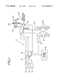
- FIG. 1 is an overall schematic view showing the configuration of a vehicle safety running control system according to the invention.
- reference numeral 10 designates a vehicle (partially illustrated by wheels W, etc.) having a steering mechanism (not shown) manipulated by the vehicle operator.
- a laser radar (or lidar) 12 which is mounted in the proximity of the headlight (not shown) emits a laser beam (a narrow beam of coherent, powerful and nearly nonchromatic electromagnetic radiation energy in the form of light) horizontally along the course of vehicle travel and receives an energy reflected from an obstacle or object (such as another vehicle present ahead of the subject vehicle 10 ).
- the intensity of the reflected energy depends on the laser beam absorption of the target and is greatest when reflected by a reflector provided in a vehicle taillamp.
- the laser radar 12 is connected to a radar output processing unit 14 which is comprised of a microcomputer.
- the radar output processing unit 14 detects the distance (relative distance) to an obstacle or object from the vehicle 10 by measuring the time interval between transmission of the energy and reception of the reflected energy, which establishes the range of the obstacle in the beam's path. Moreover, the laser radar output processing unit 14 detects the (relative) speed of the obstacle by differentiating the measured distance, and detects the direction or orientation of the obstacle from the reflected energy to obtain two-dimensional information describing the obstacle.
- the output of the laser radar processing unit 14 is forwarded to an ECU (Electronic Control Unit) 16 which is also comprised of a microcomputer.
- ECU Electronic Control Unit
- obstacle means an object which presents as a barrier to the subject vehicle; typically another vehicle running ahead on the road.
- a yaw rate sensor 18 is provided at the center of the vehicle 10 to generate a signal indicative of the yaw rate (yaw angular velocity acting at the center of gravity of the vehicle 10 about the gravitational or vertical direction).
- the output of the yaw rate sensor 18 is sent to the ECU 16 .
- a vehicle speed sensor 20 is provided in the proximity of a drive shaft (not shown) to generate a signal indicative of the vehicle (traveling or road) speed of the vehicle 10 .
- a steer angle sensor 21 is provided in the proximity of a steering wheel (not shown) of the steering manipulated mechanism to generate a signal indicative of the steer angle input by the vehicle driver.
- the outputs of the sensors 18 , 20 , 21 are sent to the ECU 16 .
- Reference numeral 22 indicates a braking system of the vehicle 10 .
- a foot brake (brake pedal) 24 is connected, via a negative-pressure booster 26 , to a master cylinder 28 .
- the negative-pressure booster 26 has a diaphragm (not shown) which partitions the inside of the booster into two chambers such that the ratio of the negative pressure introduced from the engine intake system (not shown) to the atmospheric pressure introduced from outside of the engine is regulated to determine the position of the diaphragm which determines the force to boost the vehicle operator's brake pedal depression.
- the master cylinder 28 supplies, via oil paths 30 , hydraulic pressure (brake fluid pressure), at a pressure in response to the boosted braking force, to the brake (not shown) provided at the respective wheels W to slow or stop the rotation thereof.
- hydraulic pressure brake fluid pressure
- An electromagnetic solenoid valve 36 is provided at an appropriate location of the introduction system of the negative pressure and atmospheric pressure (not fully shown).
- the electromagnetic solenoid valve 36 is connected, via a driver circuit (not shown), to the ECU 16 to receive a command signal (a duty-ratio signal in Pulse Width Modulation) generated by the ECU 16 .
- the electromagnetic solenoid valve 36 opens/closes in response to the command signal to regulate the ratio of the negative pressure to the atmospheric pressure and operates the braking system 22 to automatically brake (i.e., to decelerate independently of the vehicle operator's brake pedal depression) the vehicle.
- An alarm system (e.g., a visible indicator or audio system) 40 is provided in the proximity of the vehicle operator's seat (not shown) and is connected to the ECU 16 to receive a command signal, and alerts the vehicle operator in response to the command signal generated by the ECU 16 .
- FIG. 2 is a flow chart showing the operation of the system
- FIG. 3 is a block diagram showing the configuration of the system in a functional manner.
- the system includes a first block for calculating quantities of state, a second block for determining automatic braking operation, and a third block for calculating a deceleration command value.
- the first block calculates the distance and speed of an obstacle (object such as other vehicle running ahead of the subject vehicle 10 ) relative to the subject vehicle 10 , the speed (traveling speed) and acceleration (vehicle acceleration) of the subject vehicle 10 , etc., based on the detected data obtained by the laser radar 12 (more precisely the radar output processing unit 14 ) and the other sensors such as the vehicle speed sensor 20 . It should be noted that in this specification the term “acceleration” may be used to indicate both acceleration and deceleration.
- the second block determines the possibility of contact with the obstacle based on the quantities of states calculated by the first block and determines whether the automatic braking operation should be conducted.
- the third block calculates a deceleration command value based on the determination of the second block and calculates a command value to be supplied to the electromagnetic solenoid valve 36 .
- the second and third blocks determine a threshold value in terms of the relative distance for avoiding contact by steering and that for avoiding contact by braking, based on the calculated quantities of states, i.e., the relative distance and relative speed (between the obstacle and the subject vehicle 10 ), the speed and acceleration of the subject vehicle 10 , etc.
- the control will be explained taking as an example a situation in which the relative speed is relatively low and the relative distance for avoiding contact by steering is greater than that for avoiding contact by braking.
- the braking system 22 is operated through the electromagnetic solenoid valve 36 to automatically brake the vehicle 10 and, if desired, the alarm system 40 is operated to alert the vehicle driver. Since it is perceived in this situation that the contact can be avoided by braking, the deceleration command value is determined to be small.
- the deceleration command value is determined to be greater such that the vehicle is slowed at a greater deceleration.
- the alarm system 40 is operated first and the braking system 22 is then operated.
- the third block calculates the deceleration command value based on the determination of the second block, calculates the deceleration command value and the specific command value (the duty-ratio signal) based on the deceleration command value and outputs to the electromagnetic solenoid valve 36 through a driver circuit (not shown) to operate the same.
- the second block determines the possibility of contact with the obstacle, when the obstacle, once detected, is lost during automatic braking operation, based on the information obtained up to the time when the obstacle was lost.
- the third block corrects the deceleration command value based on the determined possibility of contact with the obstacle.
- the program shown is based on the situation wherein the obstacle, once detected, is lost when the automatic braking by the braking system 22 has been operated in response to the obstacle detection.
- the program is executed, for example, once every 100 milliseconds.
- the program begins in S 10 in which it is determined whether the obstacle is lost. When the result is affirmative, the program proceeds to S 12 in which the possibility of contact with the obstacle is determined based on the information obtained up to the time when the obstacle was lost.
- FIG. 4 is a subroutine flow chart showing the determination of the contact possibility.
- the contact possibility is determined by predicting or estimating a prospective relative distance, etc. Specifically, when it is predicted that the relative distance will decrease in future, it can be anticipated that the contact possibility will increase in future. Accordingly, a relative distance reference value (named “Lc 1 ”; for example, 0 meters or thereabout) is set as a reference value for predicting a future contact possibility. Also, a prospective relative distance is predicted and, if it is not more than the reference value Lc 1 , it is determined that the contact possibility is great.
- Lc 1 relative distance reference value
- the program begins in S 100 in which the prospective relative distance X which would presumably result or occur in future, and the relative speed ⁇ V 1 are predicted.
- the current relative distance X 1 and the current obstacle speed V 1 can be estimated or calculated as follows;
- X 1 X 0 +( V ⁇ 0 t+ 1 ⁇ 2 ⁇ a 0 ⁇ t 2 ) ⁇ Vdt
- V 1 V 0 + a 0 ⁇ t
- V means the subject vehicle speed and it is assumed that the subject vehicle runs at a constant deceleration.
- the current relative speed ⁇ V 1 (between the subject vehicle and the obstacle) can be predicted as follows.
- the prospective relative distance X (at a time T after the current time) can be expressed as Eq. 1.
- a means the subject vehicle acceleration (deceleration) as mentioned above.
- the condition that the prospective relative distance X becomes not more than the reference value Lc 1 in future (i.e., T>0), will accordingly be one from among the following. In other words, if one among from 1) to 3) is satisfied, it can be predicted that X ⁇ Lc 1 .
- the program proceeds to S 102 in which it is determined whether the prospective relative distance X is not more than the reference value Lc 1 , in other words, it is determined whether any condition from among 1) to 3) is satisfied.
- the program proceeds to S 104 in which it is determined that the possibility of contact with the obstacle is great.
- the program proceeds to S 14 in which it is determined whether the possibility of contact, thus obtained, is great, and if the result is affirmative, to S 16 in which the deceleration command value increased by addition of a predetermined unit amount to increase the vehicle deceleration.
- the predetermined unit amount is, for example, a value corresponding to 0.5 G/sec. (G: a value corresponding to the acceleration of gravity).
- G a value corresponding to the acceleration of gravity
- the predetermined unit amount used in S 16 and S 20 may be different, or the amount may be variable depending upon the situation.
- the system can appropriately cope with a situation in which an obstacle, once detected, is lost during automatic braking operation, without degrading the driving feeling or comfort and without causing the vehicle driver to experience annoyance, while ensuring obstacle avoidance without fail.
- the system can cope with the situation such that the driving feeling or comfort is prevented from being degraded, and the vehicle driver is not caused to experience annoyance. Furthermore, since the deceleration command value is changed by the unit amount, the vehicle driver's maneuver will not be affected by the vehicle deceleration change.
- FIG. 6 is a subroutine flow chart, similar to FIG. 4, but showing the operation of the system according to a second embodiment of the invention.
- the prospective relative distance, etc. are predicted similarly to the first embodiment, and is configured such that the possibility of contact is great when the prospective relative distance is small, but the relative speed at that time is great.
- the program begins in S 200 in which the prospective relative distance X and a prospective relative speed ⁇ V 2 are predicted, and proceeds to S 202 where it is determined whether the prospective relative distance is not more than a reference value (expressed as “Lc 2 ”, being a value similar to that of the first embodiment). When the result is affirmative, the program proceeds to S 204 in which it is determined that the prospective relative distance ⁇ V 2 is not less than a reference value Vc.
- the relative distance reference value Lc 2 e.g., 0 meter
- the relative speed reference value Vc e.g., 20 km/h
- the condition that the prospective relative distance X is not more than the reference value Lc 2 will be one from among 1) to 3) mentioned in the first embodiment.
- Time T 2 (a time until X becomes not more than Lc 2 ) can be obtained as follows.
- T 2 ⁇ ( ⁇ V 1 2 +2 ⁇ ( a ⁇ a 0 ) ⁇ ( X 1 ⁇ Lc 2 )) 1 ⁇ 2 ⁇ V 1 ⁇ /( a ⁇ a 0 )
- T 2 ( X 1 ⁇ Lc 2 )/ ⁇ V 1
- the prospective relative speed ⁇ V 2 can be obtained as follows.
- ⁇ V 1 means the current relative speed.
- the contact possibility determination in the second embodiment can accordingly be conducted more accurately than that in the first embodiment, thereby enabling the system to cope more appropriately with a situation in which an obstacle, once detected, is lost during automatic braking operation, without degrading the driving feeling or comfort and without causing the vehicle driver to experience annoyance, while ensuring obstacle avoidance without fail.
- FIG. 7 is a subroutine flow chart, similar to FIG. 4, but showing the operation of the system according to a third embodiment of the invention.
- the third embodiment concerns to a case where the possibility of contact is determined to be small.
- the program begins in S 300 in which the current relative distance X 1 and the current relative speed ⁇ V 1 are obtained, and proceeds to S 302 where it is determined based on the determined parameters whether the subject vehicle could come into contact with the obstacle if the situation is left as it is.
- the contact possibility determination in the third embodiment in particular in the determination that the possibility of contact is small, can accordingly be conducted more accurately than that in the foregoing embodiments, thereby enabling the system to cope more appropriately with a situation in which an obstacle, once detected, is lost during automatic braking operation, without degrading the driving feeling or comfort and without causing the vehicle driver to experience annoyance, while ensuring obstacle avoidance without fail.
- FIG. 8 is a subroutine flow chart, similar to FIG. 4, but showing the operation of the system according to a fourth embodiment of the invention.
- the fourth embodiment concerns to a case where the contact possibility is determined to be small.
- the program begins in S 400 in which the current relative distance X 1 , the current relative speed ⁇ V 1 , a position of the obstacle in the lateral direction Y 0 and a moving amount of the subject vehicle in the same direction Y 1 are determined or estimated.
- the “lateral direction” means the vehicle-width direction as expressed in FIG. 9 by Y, etc.
- the program proceeds to S 402 in which it is determined based on the determined parameters whether the subject vehicle could come into contact with the obstacle if the situation is left as it is. When the result is affirmative, the program proceeds to S 404 in which it is determined that the contact possibility is great.
- a moving amount of the obstacle in the lateral direction Y within the time t and the moving amount of the subject vehicle 10 in the same direction Yl can be estimated or determined as follows.
- ⁇ indicates the yaw rate of the subject vehicle 10 .
- the width (length in the lateral direction) of the obstacle is obtained from the output of the radar output processing unit 14 , or may be assumed to be a predetermined value (such as 2 meters).
- the distance in the lateral direction d between the subject vehicle 10 and the obstacle 100 will be calculated as follows.
- the fourth embodiment has the same effect and advantages of the third embodiment, thereby enabling the system to cope more appropriately with a situation in which an obstacle, once detected, is lost during automatic braking operation, without degrading the driving feeling or comfort and without causing the vehicle driver to experience annoyance, while ensuring obstacle avoidance without fail.
- the contact possibility decrease can be determined more properly in the fourth embodiment, thereby preventing the vehicle deceleration from being continued unnecessarily.
- FIG. 10 is a subroutine flow chart, similar to FIG. 4, but showing the operation of the system according to a fifth embodiment of the invention.
- the fifth embodiment is a combination of the third and fourth embodiments.
- the program begins in S 500 in which the current relative distance X 1 , the current relative speed ⁇ V 1 , the position of the obstacle in the lateral direction Y 0 and the moving amount of the subject vehicle in the same direction Y 1 are determined or estimated.
- the program proceeds to S 502 in which it is determined based on the determined parameters whether the subject vehicle could come into contact with the obstacle if the situation is left as it is. When the result is affirmative, the program proceeds to S 504 in which it is determined that the contact possibility is great.
- the fifth embodiment has the same effect and advantages of the third and fourth embodiments, thereby enabling the system to cope more appropriately with a situation in which an obstacle, once detected, is lost during automatic braking operation, without degrading the driving feeling or comfort and without causing the vehicle driver to experience annoyance, while ensuring obstacle avoidance without fail.
- FIG. 11 is a subroutine flow chart, similar to FIG. 2, but showing the operation of the system according to a sixth embodiment of the invention.
- the possibility of contact is determined and then it is determined whether the vehicle driver has avoided the obstacle by steering and the deceleration command value is corrected based on the determination.
- the program begins in S 600 in which the possibility of contact is determined using any manner mentioned in the foregoing embodiment, and proceeds to S 602 in which it is determined whether the determined possibility of contact is great. When the result is affirmative, the program proceeds to S 604 in which it is determined whether the contact is being avoided (or has been avoided) by vehicle driver's steering.
- the steer angle is determined from the output of the steer angle sensor 21 .
- the differential (or difference) of the determined steer angle is then calculated to determine the steer angular velocity. Since the direction in which the steering wheel is moved is not significant, the steer angle and steer angular velocity are determined as an absolute value.
- a characteristic shown in FIG. 12 is prepared beforehand and by comparing the calculated absolute values with a reference value (line) S (illustrated in the figure), it can be determined that the vehicle driver steers to avoid the obstacle when the calculated absolute values exceeds the reference value (line) S.
- the program skips S 606 to hold the current vehicle deceleration so as not to disturb the vehicle driver's contact avoidance by steering.
- the program proceeds to S 608 in which it is determined whether the possibility of contact is small, and if the result is affirmative, the program proceeds to S 610 in which the unit amount is subtracted from the deceleration command value to decrease the vehicle deceleration.
- the program skips S 610 to hold the current deceleration command value.
- FIG. 13 is a time chart showing the procedures illustrated in the flow chart of FIG. 1 . Assuming that the automatic braking operation is started at time t 0 and the obstacle is lost at time t 1 , the vehicle deceleration (corresponding to the deceleration command value) is controlled to be increased gradually with respect to time for a period during which the possibility of contact is successively determined to be great.
- the automatic braking may be terminated at time t 5 if the vehicle deceleration becomes not more than a predetermined value such as 0.1 G, as will be referred to in an eighth embodiment of the invention.
- the sixth embodiment has similar effects and advantages of the foregoing embodiments, thereby enabling the system to cope more appropriately with a situation in which an obstacle, once detected, is lost during automatic braking operation, without degrading the driving feeling or comfort and without causing the vehicle driver to experience annoyance, while ensuring obstacle avoidance without fail.
- control in the sixth embodiment can prevent interference with the driver's steering from happening.
- FIG. 14 is a subroutine flow chart, similar to FIG. 2, but showing the operation of the system according to a seventh embodiment of the invention.
- the deceleration command value is determined or corrected based on the condition of steering.
- the program begins in S 700 in which the possibility of contact is determined using any manner mentioned in the foregoing embodiments, and proceeds to S 702 in which it is determined whether the determined possibility of contact is great. When the result is affirmative, the program proceeds to S 704 in which an amount to be added to the deceleration command value is determined based on the condition of steering.
- a characteristic shown in FIG. 15 is prepared beforehand. As illustrated, the characteristic has three areas each defining the amount to be added to the deceleration command value, specifically defined in terms of rate of increase (the amount) as 0.1 G/sec., 0.3 G/sec., and 0.5 G/sec.
- rate of increase the amount
- one from among three areas is selected by the absolute values of the steer angle and steer angular velocity (calculated in the same manner as that in the sixth embodiment) to determine the rate (amount) defined there.
- the characteristic is predetermined such that the increase rate (amount) decreases with increasing absolute values of the steer angle and steer angular velocity.
- the seventh embodiment has similar effects and advantages of the foregoing embodiments, thereby enabling the system to cope more appropriately with a situation in which an obstacle, once detected, is lost during automatic braking operation, without degrading the driving feeling or comfort and without causing the vehicle driver to experience annoyance, while ensuring obstacle avoidance without fail.
- control in the seventh embodiment can similarly prevent interference with the driver's steering from happening.
- control in the seventh embodiment can suppress the increase of the deceleration command to a necessary and least extent.
- FIG. 16 is a subroutine flow chart, similar to FIG. 14, but showing the operation of the system according to the aforesaid eighth embodiment of the invention.
- the program begins in S 800 and proceeds up to S 808 in the same manner as in the foregoing embodiments to determine or correct the deceleration command value based on the possibility of contact.
- the program then proceeds to S 810 in which it is determined whether the vehicle deceleration is not more than a prescribed value (e.g., 0.1 G), and if the result is affirmative, the program proceeds to S 812 in which the automatic braking operation is terminated or discontinued. If the result in S 810 is negative, the program skips to S 812 to continue the automatic braking operation.
- a prescribed value e.g., 0.1 G
- the eighth embodiment has similar effects and advantages of the foregoing embodiments, thereby enabling the system to cope more appropriately with a situation in which an obstacle, once detected, is lost during automatic braking operation, without degrading the driving feeling or comfort and without causing the vehicle driver to experience annoyance, while ensuring obstacle avoidance without fail.
- the system according to the eighth embodiment can properly determine the time for terminating the automatic braking.
- FIG. 17 is a flow chart showing the operation of the system according to a ninth embodiment of the invention
- FIG. 18 is a block diagram, similar to FIG. 3, but showing the configuration of the system in a functional manner.
- the system according to the ninth embodiments includes a first block for calculating quantities of state, a second block for determining automatic braking, and a third block for calculating a deceleration command value.
- the operation of the blocks are similar to those in the foregoing embodiments, except for the fact that the second block determines or calculates not only the possibility of contact with the obstacle, but also the degree of certainty of obstacle.
- the degree of certainty of obstacle is a kind of so-called certain factor, and represents the degree to which it is believed that the detected is, in fact, an obstacle.
- the degree of certainty of obstacle is determined in numbers ranging from 0, indicating definite evidence that the obstacle is false, to 1, indicating definite evidence that obstacle is true.
- the system determines or calculates the degree of certainty of obstacle such that the confidence increases with increasing degree of certainty of obstacle.
- the program begins in S 900 in which the degree of certainty of obstacle is determined or calculated.
- FIG. 19 is a subroutine flow chart showing the determination of the degree of certainty of obstacle.
- the program begins in S 1000 in which it is determined whether an obstacle is detected, and if the result is affirmative, the program proceeds to S 1002 in which it is determined whether the obstacle was not detected in the last program loop of FIG. 2 flow chart.
- the program proceeds to S 1004 in which the initial value of the degree of certainty of obstacle is determined based on the detected position of the obstacle in the detection range of the laser radar 12 .
- the obstacle normally appears first at the end (more specifically at the distal (corresponding to the farthest position) end or at the left or right end) of the radar detection range. Accordingly, if the first detected position (in the radar detection range) at which the obstacle is detected for the first time is at or close to the distal end or the left or right edge, the confidence or certainty that it is an obstacle is believed to be great such that the initial value of the degree is determined to be great.
- the position at which the obstacle is detected for the first time is relatively shorter than the farthest distal end and is at or close to the center of the radar detection range, it may be a metal piece or a sheet of paper blowing in the wind.
- the confidence or certainty that it is an obstacle (typically another vehicle) is believed to small and hence, the initial value of the degree is determined to be small.
- the initial value of the degree is determined to be 0.4; if it is within area A 2 , the value is determined to be 0.2; and if it is within area A 3 , the value is determined to be 0. It is preferable to change the values in response to the degradation of the radar detection accuracy.
- a reference degree of certainty of obstacle is predetermined with respect to the intensity of received energy of the laser radar 12 , as illustrated in FIG. 21 .
- the calculated degree is compared with the reference value and if the calculated degree is found to exceed the reference value, the calculated degree is limited to the reference value.
- the upper limit of the degree is 1.0.
- the amount is determined by retrieving characteristics, shown in FIG. 22, prepared in advance by the last detected position, more precisely the last position before the detected obstacle was lost. If the last position is at the right or left edge of the detection area, it can be believed that the obstacle moved in the lateral direction or the subject vehicle itself moved in the lateral direction and avoided it. If this is the case, since the possibility of contact is believed to be little, the degree of certainty of obstacle is decreased. However, if the last position is close to the subject vehicle, since the possibility of contact still exists even if the obstacle is out of sight, the degree is kept unchanged.
- the degree of certainty of obstacle is kept unchanged; if it is within B 2 , the degree is decreased by 0.2; and if it is within B 3 , the degree is decreased by 0.4.
- the lateral relative speed should be determined in terms of absolute value such that the decrease amount (ranging from 0 to 0.5) is retrieved from the illustrated characteristic by the calculated lateral relative speed.
- the decrease amount may be used together with the amount shown in FIG. 22, or may be used instead.
- FIG. 24 illustrates one example of the transit of degree of certainty with respect to time. Assuming that the obstacle is detected at time t 0 , the degree of certainty is set to the initial value. If the obstacle is continuously detected, the degree of certainty is gradually increased with respect to time.
- the decrease amount is set to be a large amount to decrease the degree of certainty sharply as shown by the solid line.
- the decrease amount may alternatively set to be smaller such that the degree of certainty decreases gradually as shown by the phantom line.
- the initial value of the degree of certainty is determined in S 1004 based on the relative position (detected position) of the obstacle, it is alternatively possible to determine the initial value based on the intensity of reflected energy of radar 12 using the characteristic illustrated in FIG. 21 . In that case, S 1008 should be deleted or is left, but other characteristics should be prepared.
- the program proceeds to S 902 in which it is determined whether the obstacle is lost during the automatic braking operation, and if the result is negative, the program proceeds to S 904 in which the deceleration command value is determined or calculated based on the data detected in this time (program loop) in the manner shown in FIG. 18 .
- the program then proceeds to S 908 in which it is determined whether the degree of certainty exceeds a predetermined value (such as 0.6), and if the result is affirmative, since the degree assigned to the obstacle is high, the program proceeds to S 910 in which the deceleration command value is determined based on the estimated information obtained in the same manner as that mentioned in the first embodiment. If the result in S 908 is negative, since the degree is believed to be not high, the program proceeds to S 912 in which the deceleration command value is determined based on the degree of certainty, more specifically, the deceleration command value remains unchanged or is decreased.
- a predetermined value such as 0.6
- FIG. 25 is a time chart, similar to FIG. 13, but showing the procedures illustrated in the flow chart of FIG. 17 . Assuming that the automatic braking operation is started at time t 0 and the obstacle is lost at time t 1 , the automatic braking operation is conducted based on the estimated obstacle information when the degree of certainty exceeds the predetermined value (0.6).
- the automatic braking operation is conducted based on the degree of certainty. Specifically, this is done by retrieving a table (whose characteristics are illustrated in FIG. 26) using the degree of certainty as an address datum to determine a time or period Tn (n: 1-3) during which the deceleration (now being applied) is held. As illustrated, the time Tn decreases with decreasing degree of certainty.
- time lapse is measured and when the time reaches the retrieved value Tn, the operation of the braking system 22 is terminated or discontinued.
- the ninth embodiment is configured such that, when the obstacle, once detected, is lost or missed, the degree of certainty of obstacle is determined based on the detection information obtained before the time and when the determined degree of certainty exceeds the predetermined value, the automatic braking operation for contact avoidance is conducted based on the estimated information, while the operation is conducted based on the degree of certainty when the degree of certainty is not more than the predetermined value.
- the system according to the ninth embodiment can appropriately cope with a situation in which an obstacle, once detected, is lost, by determining the degree of certainty of obstacle and by controlling the operation of an automatic braking operation based on the determined degree of certainty, thereby preventing the driving feeling or comfort from being degraded and the vehicle driver from experiencing annoyance, while ensuring obstacle avoidance without fail.
- the automatic braking operation or vehicle deceleration is held for a predetermined time and then terminated even if the presence of the obstacle or object is uncertain, in other words, the automatic braking operation is not terminated suddenly, thereby preventing the driving feeling or comfort from being degraded and the vehicle driver from experiencing annoyance more effectively, while ensuring obstacle avoidance without fail.
- the time to hold the automatic braking operation or vehicle deceleration is set to decrease with decreasing degree of certainty of obstacle, thereby enabling the system to determine the time to continue the automatic braking operation properly, while ensuring obstacle avoidance without fail.
- FIG. 28 and FIG. 29 are views, similar to FIG. 26 and FIG. 27, but showing the operation of the system according to a tenth embodiment of the invention, which shows the operation of S 912 in the flow chart of FIG. 17 .
- the rate of decrease of the vehicle deceleration (i.e., the speed to terminate or relieve the automatic braking operation) is determined based on the degree of certainty.
- the degree of certainty is used to retrieve a table (whose characteristics are shown in FIG. 28) to determine the rate of decrease (coefficient) kn (n: 1-3).
- the rate of decrease kn increases with decreasing degree of certainty, in other words, the vehicle deceleration is decreased earlier as the degree certainty decreases.
- the braking system 22 is made inoperable in response to the retrieved rate of decrease kn.
- the decrease of the vehicle deceleration is immediately started when it is determined the obstacle is lost.
- the rest of the tenth embodiment is the same as that of the ninth embodiment.
- the system according to the tenth embodiment can appropriately cope with a situation in which an obstacle, once detected, is lost, by determining the degree of certainty of obstacle and by controlling the operation of an automatic braking operation based on the determined degree of certainty, thereby preventing the driving feeling or comfort from being degraded and the vehicle driver from experiencing annoyance, while ensuring obstacle avoidance without fail.
- the system is configured such that the rate of decrease of the vehicle deceleration increases with decreasing degree of certainty, in other words, the time to continue the automatic braking operation is shortened as the confidence that the detected was an obstacle decreases, i.e., the need to decelerate decreases. With this procedure, the time to hold the automatic braking operation or vehicle deceleration can be determined more properly.
- FIG. 30 is a time chart, similar to FIG. 29, but showing the operation of the system according to an eleventh embodiment of the invention, which also shows the operation of S 912 in the flow chart of FIG. 17 .
- both the time to hold the vehicle deceleration and the rate of decreasing the vehicle deceleration is determined based on the degree of certainty. Specifically, when the degree of certainty is great, the time is made long and the decreasing speed is small. On the other hand, when the degree of certainty is small, the time is shortened and the decreasing speed is enlarged.
- the rest of the eleventh embodiment is the same as that of the ninth embodiment.
- the system according to the eleventh embodiment can appropriately cope with a situation in which an obstacle, once detected, is lost, by determining the degree of certainty of obstacle and by controlling the operation of an automatic braking operation based on the determined degree of certainty, thereby preventing the driving feeling or comfort from being degraded and the vehicle driver from experiencing annoyance, while ensuring obstacle avoidance without fail.
- the system according to the eleventh embodiment can determine the time to continue the automatic braking operation more properly when the obstacle is lost.
- the foregoing embodiments are configured to provide for a system for controlling safety running of a vehicle ( 10 ), including: obstacle detecting means (laser radar 12 , radar output processing unit 14 , ECU 16 ) for detecting an obstacle ( 100 ) present ahead on a course of travel of the vehicle; and vehicle device operating means (ECU 16 ) for operating a device (braking system 22 ) of the vehicle to conduct maneuvers necessary for avoiding contact with the obstacle.
- obstacle detecting means laser radar 12 , radar output processing unit 14 , ECU 16
- ECU 16 vehicle device operating means for operating a device (braking system 22 ) of the vehicle to conduct maneuvers necessary for avoiding contact with the obstacle.
- the vehicle device operating means controls operation of the device based on a parameter (possibility of contact, degree of certainty of obstacle) relating to the obstacle when it is found that the obstacle detected by the obstacle detecting means is lost.
- the words “operating a device of the vehicle to conduct maneuvers necessary for avoiding contact with the obstacle” includes to operate the braking system in the embodiments as mentioned above. However, this further includes to operate the alarm system 40 to alert the vehicle driver, to operate a steering system (not shown) to avoid the contact, to gear shift or to cut fuel supply to the engine so as to decrease drive output to decelerate the vehicle, etc.
- the device is a braking system ( 22 ) to brake the vehicle ( 10 ); and it further includes: vehicle speed detecting means (vehicle speed sensor 22 , ECU 16 ) for detecting a speed of the vehicle (V); relative distance determining means (laser radar 12 , radar output processing unit 14 , ECU 16 , first block for calculating quantities of state, S 100 , S 200 , S 300 , S 400 , S 500 ) for determining a distance of the obstacle relative to the vehicle (X, X 1 ) based on a detection result of the obstacle detecting means; relative speed detecting means (laser radar 12 , radar output processing unit 14 , ECU 16 , first block for calculating quantities of state, S 100 , S 200 , S 300 , S 400 , S 500 ) for determining a speed of the obstacle relative to the vehicle ( ⁇ V 1 , ⁇ V 1 , ⁇ V 2 ) based on a detection result of the obstacle detecting means; contact possibility determining means (
- the contact possibility determining means determines the possibility of contact, if the obstacle is lost when the braking system is being operated, determines the relative distance (prospective relative distance X) based on the detection result of the obstacle detecting means obtained before the obstacle was lost, and when the determined relative distance (X) is not more than a first predetermined value (Lc 1 ), determines the possibility of contact to be great (ECU 16 , second block for determining automatic braking operation, S 12 , S 100 -S 108 ).
- the contact possibility determining means determines the possibility of contact, determines the relative distance (prospective relative distance X) based on the detection result of the obstacle detecting means obtained before the obstacle was lost, and when the determined relative distance (X) is not more than a second predetermined value (Lc 2 ) and when the relative speed (prospective relative speed ⁇ V 2 ) is not less than a third predetermined value (Vc), determines the possibility of contact to be great (ECU 16 , second block for determining automatic braking operation, S 12 , S 200 -S 210 ).
- the braking system operating means increases the deceleration by an amount with respect to time when the possibility of contact is determined to be great (ECU 16 , third block for calculating a deceleration command value, S 18 -S 22 , S 602 -S 610 , S 702 -S 710 , S 802 -S 812 ).
- the system further includes; steer determining means (steer angle sensor 21 , ECU 16 ) for determining whether the steering is operated; and wherein the braking system operating means terminates increasing the deceleration or decreases a rate of increasing the deceleration when the steering determining means determines that the steering is operated (ECU 16 , third block for calculating a deceleration command value, S 604 -S 606 , S 704 -S 706 ).
- the contact possibility determining means determines the possibility of contact, determines the relative distance based on the detection result of the obstacle detecting means obtained before the obstacle was lost, and when the determined relative distance is not more than a fourth predetermined value (zero), determines the possibility of contact to be small (ECU 16 , second block for determining automatic braking operation, S 306 -S 308 , S 506 -S 512 ).
- the contact possibility determining means determines the possibility of contact, determines the relative distance based on the detection result of the obstacle detecting means obtained before the obstacle was lost, and when the relative speed is not more than a fifth predetermined value (zero), determines the possibility of contact to be small (ECU 16 , second block for determining automatic braking operation, S 306 -S 308 , S 506 -S 512 ).
- the system further includes: a lateral relative position determining means for determining a position (d) of the obstacle relative to the vehicle in a vehicle-width direction (ECU 16 , S 400 , S 500 ); and wherein, if the obstacle is lost when the braking system is being operated, the contact possibility determining means determines the possibility of contact, determines the lateral relative position based on the detection result of the lateral relative position determining means obtained before the obstacle was lost, and determines that the vehicle has avoided the obstacle based on the determined relative position, determines the possibility of contact to be small (ECU 16 , second block for determining automatic braking operation, S 406 , S 408 , S 512 , S 508 ).
- the braking system operating means decreases the deceleration by an amount with respect to time when the possibility of contact is determined to be small (ECU 16 , third block for calculating a deceleration command value, S 18 -S 22 , S 602 -S 610 , S 702 -S 710 , S 802 -S 812 ).
- the braking system operating means terminates operation of the braking system when the deceleration is not more than a prescribed value (0.1 G; ECU 16 , third block for calculating a deceleration command value, S 810 -S 812 ).
- the system further includes: degree of certainty determining means (ECU 16 , second block for determining automatic braking operation, S 900 , S 1000 -S 1012 ) for determining a degree of certainty to determine whether the detected by the obstacle detecting means is, in fact, the obstacle, as the parameter, when the detected obtained by the obstacle detecting means is lost; and wherein the vehicle device operating means controls operation of the device based on the determined degree of certainty (ECU 16 , third block for calculating a deceleration command value, S 902 - 912 ).
- degree of certainty determining means ECU 16 , second block for determining automatic braking operation, S 900 , S 1000 -S 1012
- the vehicle device operating means controls operation of the device based on the determined degree of certainty (ECU 16 , third block for calculating a deceleration command value, S 902 - 912 ).
- the certainty degree determining means determines an initial value of the degree of certainty based on a position (An, Bn) of the detected relative to the vehicle (ECU 16 , second block for determining automatic braking operation, S 900 , S 1004 ).
- the degree of certainty determining means determines the initial value of the degree of certainty to be small when at least one of the relative position (An) in a vehicle longitudinal direction of the detected at which it is obtained for the first time and the lateral relative position (Bn) from the center position of teh vehicle in the vehicle-width direction, is small (ECU 16 , second block for determining automatic braking operation, S 900 , S 1004 ).
- the degree of certainty determining means determines the degree of certainty based on at least one of a time duration of detection and an intensity of received energy of detection obtained by the obstacle detecting means (ECU 16 , second block for determining automatic braking operation, S 900 , S 1004 ).
- the degree of certainty determining means determines the degree of certainty based on a time duration of detection and determines the degree of certainty to be increased as the time increases (ECU 16 , second block for determining automatic braking operation, S 900 , S 1004 ).
- the degree of certainty determining means decreases the degree of certainty based on a position of the detected relative to the vehicle at which the detected was lost (ECU 16 , second block for determining automatic braking operation, S 900 , S 1012 ).
- the degree of certainty determining means decreases the degree of certainty based on a speed of the detected relative to the vehicle at which the detected was lost (ECU 16 , second block for determining automatic braking operation, S 900 , S 1012 .
- the system further includes: braking system operating means (ECU 16 , second block for determining automatic braking operation, S 900 -S 912 ), for operating a braking system ( 22 ) to brake the vehicle at a deceleration based on the determined degree of certainty; and information estimating means (ECU 16 , first block for calculating quantities of state, S 906 ) for estimating information concerning at least one of a position and a speed of the obstacle, if the detected is lost when the braking system is being operated, based on the detection result of the obstacle detecting means obtained before the detected was lost; and wherein the braking system operates the braking system based on the information when the degree of certain is determined to be great, if the detected is lost during operating the braking system, while operating the braking system based on the degree of certainty when the degree of certain is determined to be small, if the detected is lost during operation of the braking system, for operating a braking system ( 22 ; ECU 16 , second block for determining automatic braking operation, S 900
- the braking system operating means operates the braking system for a time which decreases with decreasing degree of certainty (ECU 16 , second block for determining automatic braking operation, S 900 -S 912 ).
- the braking system operating means operates the braking system to change a rate of the deceleration based on the degree of certainty (ECU 16 , second block for determining automatic braking operation, S 900 -S 912 ).
- the laser radar 12 is used as a means for detecting the other vehicle (obstacle), a millimeter-wave radar 14 or a visionary sensor such as a CCD camera may instead be used.
Applications Claiming Priority (4)
| Application Number | Priority Date | Filing Date | Title |
|---|---|---|---|
| JP17071898 | 1998-06-03 | ||
| JP10-170718 | 1998-06-03 | ||
| JP10-170717 | 1998-06-03 | ||
| JP17071798 | 1998-06-03 |
Publications (1)
| Publication Number | Publication Date |
|---|---|
| US6259992B1 true US6259992B1 (en) | 2001-07-10 |
Family
ID=26493638
Family Applications (1)
| Application Number | Title | Priority Date | Filing Date |
|---|---|---|---|
| US09/324,735 Expired - Lifetime US6259992B1 (en) | 1998-06-03 | 1999-06-03 | Vehicle safety running control system |
Country Status (2)
| Country | Link |
|---|---|
| US (1) | US6259992B1 (de) |
| DE (1) | DE19925643B4 (de) |
Cited By (29)
| Publication number | Priority date | Publication date | Assignee | Title |
|---|---|---|---|---|
| US6498972B1 (en) | 2002-02-13 | 2002-12-24 | Ford Global Technologies, Inc. | Method for operating a pre-crash sensing system in a vehicle having a countermeasure system |
| US6519519B1 (en) | 2002-02-01 | 2003-02-11 | Ford Global Technologies, Inc. | Passive countermeasure methods |
| US20030030555A1 (en) * | 2001-08-13 | 2003-02-13 | Cole George Stuart | Vehicle braking signal system with varying area display |
| US20030076981A1 (en) * | 2001-10-18 | 2003-04-24 | Smith Gregory Hugh | Method for operating a pre-crash sensing system in a vehicle having a counter-measure system |
| US20030106732A1 (en) * | 2001-12-11 | 2003-06-12 | Nissan Motor Co., Ltd. | Automatic brake system of wheeled motor vehicle |
| US20030139864A1 (en) * | 2002-01-24 | 2003-07-24 | Ford Global Technologies, Inc. | Post collision restraints control module |
| US6721659B2 (en) | 2002-02-01 | 2004-04-13 | Ford Global Technologies, Llc | Collision warning and safety countermeasure system |
| US20040111200A1 (en) * | 2001-11-29 | 2004-06-10 | Rao Manoharprasad K. | Vehicle sensing based pre-crash threat assessment system |
| US6775605B2 (en) | 2001-11-29 | 2004-08-10 | Ford Global Technologies, Llc | Remote sensing based pre-crash threat assessment system |
| US6831572B2 (en) | 2002-01-29 | 2004-12-14 | Ford Global Technologies, Llc | Rear collision warning system |
| US20050222742A1 (en) * | 2004-03-11 | 2005-10-06 | Nissan Motor Co., Ltd. | Assisting a vehicle driver via changes in reaction force and engine output characteristic |
| US20050267660A1 (en) * | 2004-05-14 | 2005-12-01 | Honda Motor Co., Ltd. | Vehicle operation assisiting system |
| US20050288844A1 (en) * | 2004-06-24 | 2005-12-29 | Nissan Motor Co., Ltd. | Driving assistance method and system |
| US20060195245A1 (en) * | 2004-12-07 | 2006-08-31 | Yosuke Kobayashi | Driving assisting system, method and vehicle incorporating the system |
| US20070288133A1 (en) * | 2006-06-13 | 2007-12-13 | Nissan Motor Co., Ltd. | Obstacle avoidance path computing apparatus, obstacle avoidance path computing method, and obstacle avoidance control system equipped with obstacle avoidance path computing system |
| WO2008007202A1 (en) * | 2006-07-10 | 2008-01-17 | Toyota Jidosha Kabushiki Kaisha | Driving support control device and driving support control method |
| US20080312832A1 (en) * | 2007-06-12 | 2008-12-18 | Greene Daniel H | Dual assessment for early collision warning |
| EP2077212A1 (de) | 2008-01-04 | 2009-07-08 | WABCO GmbH | Fahrerassistenzsystem |
| US20090326820A1 (en) * | 2006-08-15 | 2009-12-31 | Toyota Jidosha Kabushiki Kaisha | Braking control system and braking control method |
| CN102431553A (zh) * | 2011-10-18 | 2012-05-02 | 奇瑞汽车股份有限公司 | 汽车主动安全系统及方法 |
| US20130110370A1 (en) * | 2011-11-02 | 2013-05-02 | Toyota Jidosha Kabushiki Kaisha | Brake control device |
| WO2014083787A1 (ja) * | 2012-11-27 | 2014-06-05 | 日産自動車株式会社 | 車両用加速抑制装置及び車両用加速抑制方法 |
| US20150123778A1 (en) * | 2013-11-01 | 2015-05-07 | Nissan North America, Inc. | Vehicle contact avoidance system |
| US20150217765A1 (en) * | 2014-02-05 | 2015-08-06 | Toyota Jidosha Kabushiki Kaisha | Collision prevention control apparatus |
| US9156354B2 (en) | 2011-09-22 | 2015-10-13 | Knorr-Bremse Systeme Fuer Nutzfahrzeuge Gmbh | Driver assistance system having autonomous braking to a standstill |
| US20150329046A1 (en) * | 2012-11-21 | 2015-11-19 | Toyota Jidosha Kabushiki Kaisha | Driving-assistance device and driving-assistance method |
| US9470790B2 (en) | 2012-09-03 | 2016-10-18 | Toyota Jidosha Kabushiki Kaisha | Collision determination device and collision determination method |
| US9643576B2 (en) | 2012-10-30 | 2017-05-09 | Toyota Jidosha Kabushiki Kaisha | Collision avoidance assist device and collision avoidance assist method |
| US20180326980A1 (en) * | 2017-05-12 | 2018-11-15 | Valeo Interior Controls (Shenzhen) Co., Ltd | Method and a vehicle control system for controlling an autonomous vehicle |
Families Citing this family (3)
| Publication number | Priority date | Publication date | Assignee | Title |
|---|---|---|---|---|
| JP3580184B2 (ja) * | 1999-06-30 | 2004-10-20 | 日産自動車株式会社 | 車両用追従制御装置 |
| US6161074A (en) * | 1999-12-22 | 2000-12-12 | Visteon Global Technologies, Inc. | Method and system for continued vehicle control in an adaptive speed control system at vehicle speeds below a minimum operating speed when a sensed target disappears |
| DE10102771A1 (de) | 2001-01-23 | 2002-07-25 | Bosch Gmbh Robert | Einrichtung zum Bereitstellen von Signalen in einem Kraftfahrzeug |
Citations (12)
| Publication number | Priority date | Publication date | Assignee | Title |
|---|---|---|---|---|
| US4491840A (en) * | 1981-04-07 | 1985-01-01 | Honda Giken Kogyo Kabushiki Kaisha | Intervehicle distance control system for vehicles |
| US5332057A (en) * | 1991-08-27 | 1994-07-26 | Mazda Motor Corporation | Contact preventive apparatus for vehicles |
| JPH06298022A (ja) | 1993-04-08 | 1994-10-25 | Toyota Motor Corp | 車両用追突防止装置 |
| US5461357A (en) * | 1992-01-29 | 1995-10-24 | Mazda Motor Corporation | Obstacle detection device for vehicle |
| US5477461A (en) * | 1993-05-28 | 1995-12-19 | Bayerische Motoren Werke Aktiengesellschaft | Method for avoiding collisions between a motor vehicle and obstacles |
| US5510990A (en) * | 1992-12-08 | 1996-04-23 | Nippondenso Co., Ltd. | System for distinguishing a vehicle traveling ahead based on an adjustable probability distribution |
| US5586031A (en) * | 1993-09-20 | 1996-12-17 | Kroll Fahrzeugbau-Umwelttechnik Gmbh | Road vehicle with all wheel steering, and process for steering |
| US5612699A (en) * | 1995-02-08 | 1997-03-18 | Toyota Jidosha Kabushiki Kaisha | Vehicle radar for excluding a vehicle changing a lane from targets to track |
| US5678650A (en) * | 1993-06-30 | 1997-10-21 | Mazda Motor Corporation | Drive control system for automotive vehicle |
| US5864285A (en) * | 1996-03-01 | 1999-01-26 | Robert Bosch Gmbh | Method and apparatus for controlling the approach of a vehicle to an obstacle |
| US5913919A (en) * | 1994-05-04 | 1999-06-22 | Siemens Aktiengesellschaft | Method for collision avoidance with the assistance of a steering angle field for an autonomous mobile unit |
| US5977869A (en) * | 1996-12-04 | 1999-11-02 | Volkswagen Ag | Motor vehicle speed control method and arrangement |
Family Cites Families (2)
| Publication number | Priority date | Publication date | Assignee | Title |
|---|---|---|---|---|
| US5680097A (en) * | 1992-12-10 | 1997-10-21 | Mazda Motor Corporation | Vehicle run safety apparatus |
| JPH10129438A (ja) * | 1996-11-06 | 1998-05-19 | Toyota Motor Corp | 自動制動制御装置 |
-
1999
- 1999-06-03 US US09/324,735 patent/US6259992B1/en not_active Expired - Lifetime
- 1999-06-04 DE DE19925643A patent/DE19925643B4/de not_active Expired - Fee Related
Patent Citations (12)
| Publication number | Priority date | Publication date | Assignee | Title |
|---|---|---|---|---|
| US4491840A (en) * | 1981-04-07 | 1985-01-01 | Honda Giken Kogyo Kabushiki Kaisha | Intervehicle distance control system for vehicles |
| US5332057A (en) * | 1991-08-27 | 1994-07-26 | Mazda Motor Corporation | Contact preventive apparatus for vehicles |
| US5461357A (en) * | 1992-01-29 | 1995-10-24 | Mazda Motor Corporation | Obstacle detection device for vehicle |
| US5510990A (en) * | 1992-12-08 | 1996-04-23 | Nippondenso Co., Ltd. | System for distinguishing a vehicle traveling ahead based on an adjustable probability distribution |
| JPH06298022A (ja) | 1993-04-08 | 1994-10-25 | Toyota Motor Corp | 車両用追突防止装置 |
| US5477461A (en) * | 1993-05-28 | 1995-12-19 | Bayerische Motoren Werke Aktiengesellschaft | Method for avoiding collisions between a motor vehicle and obstacles |
| US5678650A (en) * | 1993-06-30 | 1997-10-21 | Mazda Motor Corporation | Drive control system for automotive vehicle |
| US5586031A (en) * | 1993-09-20 | 1996-12-17 | Kroll Fahrzeugbau-Umwelttechnik Gmbh | Road vehicle with all wheel steering, and process for steering |
| US5913919A (en) * | 1994-05-04 | 1999-06-22 | Siemens Aktiengesellschaft | Method for collision avoidance with the assistance of a steering angle field for an autonomous mobile unit |
| US5612699A (en) * | 1995-02-08 | 1997-03-18 | Toyota Jidosha Kabushiki Kaisha | Vehicle radar for excluding a vehicle changing a lane from targets to track |
| US5864285A (en) * | 1996-03-01 | 1999-01-26 | Robert Bosch Gmbh | Method and apparatus for controlling the approach of a vehicle to an obstacle |
| US5977869A (en) * | 1996-12-04 | 1999-11-02 | Volkswagen Ag | Motor vehicle speed control method and arrangement |
Cited By (54)
| Publication number | Priority date | Publication date | Assignee | Title |
|---|---|---|---|---|
| US7019632B2 (en) | 2001-08-13 | 2006-03-28 | George Stuart Cole | Vehicle braking signal system with varying area display |
| US20030030555A1 (en) * | 2001-08-13 | 2003-02-13 | Cole George Stuart | Vehicle braking signal system with varying area display |
| US20030076981A1 (en) * | 2001-10-18 | 2003-04-24 | Smith Gregory Hugh | Method for operating a pre-crash sensing system in a vehicle having a counter-measure system |
| US20040111200A1 (en) * | 2001-11-29 | 2004-06-10 | Rao Manoharprasad K. | Vehicle sensing based pre-crash threat assessment system |
| US6775605B2 (en) | 2001-11-29 | 2004-08-10 | Ford Global Technologies, Llc | Remote sensing based pre-crash threat assessment system |
| US6819991B2 (en) | 2001-11-29 | 2004-11-16 | Ford Global Technologies, Llc | Vehicle sensing based pre-crash threat assessment system |
| US20030106732A1 (en) * | 2001-12-11 | 2003-06-12 | Nissan Motor Co., Ltd. | Automatic brake system of wheeled motor vehicle |
| EP1323603A2 (de) * | 2001-12-11 | 2003-07-02 | Nissan Motor Company, Limited | Automatisches Bremssystem für motorgetriebenes Radfahrzeug |
| EP1323603A3 (de) * | 2001-12-11 | 2003-08-20 | Nissan Motor Company, Limited | Automatisches Bremssystem für motorgetriebenes Radfahrzeug |
| US6889786B2 (en) | 2001-12-11 | 2005-05-10 | Nissan Motor Co., Ltd. | Automatic brake system of wheeled motor vehicle |
| US20030139864A1 (en) * | 2002-01-24 | 2003-07-24 | Ford Global Technologies, Inc. | Post collision restraints control module |
| US6831572B2 (en) | 2002-01-29 | 2004-12-14 | Ford Global Technologies, Llc | Rear collision warning system |
| US6721659B2 (en) | 2002-02-01 | 2004-04-13 | Ford Global Technologies, Llc | Collision warning and safety countermeasure system |
| US6519519B1 (en) | 2002-02-01 | 2003-02-11 | Ford Global Technologies, Inc. | Passive countermeasure methods |
| US6498972B1 (en) | 2002-02-13 | 2002-12-24 | Ford Global Technologies, Inc. | Method for operating a pre-crash sensing system in a vehicle having a countermeasure system |
| US20050222742A1 (en) * | 2004-03-11 | 2005-10-06 | Nissan Motor Co., Ltd. | Assisting a vehicle driver via changes in reaction force and engine output characteristic |
| US7715969B2 (en) | 2004-03-11 | 2010-05-11 | Nissan Motor Co., Ltd. | Assisting a vehicle driver via changes in reaction force and engine output characteristic |
| US7778753B2 (en) * | 2004-05-14 | 2010-08-17 | Honda Motor Co., Ltd. | Vehicle operation assisting system |
| US20050267660A1 (en) * | 2004-05-14 | 2005-12-01 | Honda Motor Co., Ltd. | Vehicle operation assisiting system |
| US7228233B2 (en) * | 2004-06-24 | 2007-06-05 | Nissan Motor Co., Ltd. | Driving assistance method and system |
| US7729859B2 (en) * | 2004-06-24 | 2010-06-01 | Nissan Motor Co., Ltd. | Driving assistance method and system |
| US20070299612A1 (en) * | 2004-06-24 | 2007-12-27 | Nissan Motor Co., Ltd. | Driving assistance method and system |
| US20050288844A1 (en) * | 2004-06-24 | 2005-12-29 | Nissan Motor Co., Ltd. | Driving assistance method and system |
| US20060195245A1 (en) * | 2004-12-07 | 2006-08-31 | Yosuke Kobayashi | Driving assisting system, method and vehicle incorporating the system |
| US8855881B2 (en) | 2004-12-07 | 2014-10-07 | Nissan Motor Co., Ltd. | Driving assisting system, method and vehicle incorporating the system |
| US8145389B2 (en) | 2004-12-07 | 2012-03-27 | Nissan Motor Co., Ltd. | Driving assisting system, method and vehicle incorporating the system |
| US8090537B2 (en) * | 2006-06-13 | 2012-01-03 | Nissan Motor Co., Ltd. | Obstacle avoidance path computing apparatus, obstacle avoidance path computing method, and obstacle avoidance control system equipped with obstacle avoidance path computing system |
| US20070288133A1 (en) * | 2006-06-13 | 2007-12-13 | Nissan Motor Co., Ltd. | Obstacle avoidance path computing apparatus, obstacle avoidance path computing method, and obstacle avoidance control system equipped with obstacle avoidance path computing system |
| WO2008007202A1 (en) * | 2006-07-10 | 2008-01-17 | Toyota Jidosha Kabushiki Kaisha | Driving support control device and driving support control method |
| US20090326820A1 (en) * | 2006-08-15 | 2009-12-31 | Toyota Jidosha Kabushiki Kaisha | Braking control system and braking control method |
| CN101500865B (zh) * | 2006-08-15 | 2012-04-25 | 丰田自动车株式会社 | 制动控制系统与制动控制方法 |
| US8200419B2 (en) | 2006-08-15 | 2012-06-12 | Toyota Jidosha Kabushiki Kaisha | Braking control system and braking control method |
| US20080312832A1 (en) * | 2007-06-12 | 2008-12-18 | Greene Daniel H | Dual assessment for early collision warning |
| US7881868B2 (en) * | 2007-06-12 | 2011-02-01 | Palo Alto Research Center Incorporated | Dual assessment for early collision warning |
| US20090177347A1 (en) * | 2008-01-04 | 2009-07-09 | Karsten Breuer | Vehicle driver assistance system and method |
| EP2077212A1 (de) | 2008-01-04 | 2009-07-08 | WABCO GmbH | Fahrerassistenzsystem |
| US8195373B2 (en) * | 2008-01-04 | 2012-06-05 | Wabco Gmbh | Vehicle driver assistance system and method |
| US9156354B2 (en) | 2011-09-22 | 2015-10-13 | Knorr-Bremse Systeme Fuer Nutzfahrzeuge Gmbh | Driver assistance system having autonomous braking to a standstill |
| CN102431553A (zh) * | 2011-10-18 | 2012-05-02 | 奇瑞汽车股份有限公司 | 汽车主动安全系统及方法 |
| US20130110370A1 (en) * | 2011-11-02 | 2013-05-02 | Toyota Jidosha Kabushiki Kaisha | Brake control device |
| US9470790B2 (en) | 2012-09-03 | 2016-10-18 | Toyota Jidosha Kabushiki Kaisha | Collision determination device and collision determination method |
| US9643576B2 (en) | 2012-10-30 | 2017-05-09 | Toyota Jidosha Kabushiki Kaisha | Collision avoidance assist device and collision avoidance assist method |
| US20150329046A1 (en) * | 2012-11-21 | 2015-11-19 | Toyota Jidosha Kabushiki Kaisha | Driving-assistance device and driving-assistance method |
| US10421398B2 (en) * | 2012-11-21 | 2019-09-24 | Toyota Jidosha Kabushiki Kaisha | Driving-assistance device and driving-assistance method |
| US9409574B2 (en) | 2012-11-27 | 2016-08-09 | Nissan Motor Co., Ltd. | Vehicle acceleration suppression device and vehicle acceleration suppression method |
| WO2014083787A1 (ja) * | 2012-11-27 | 2014-06-05 | 日産自動車株式会社 | 車両用加速抑制装置及び車両用加速抑制方法 |
| US20150123778A1 (en) * | 2013-11-01 | 2015-05-07 | Nissan North America, Inc. | Vehicle contact avoidance system |
| US9177478B2 (en) * | 2013-11-01 | 2015-11-03 | Nissan North America, Inc. | Vehicle contact avoidance system |
| US9481365B2 (en) * | 2014-02-05 | 2016-11-01 | Toyota Jidosha Kabushiki Kaisha | Collision prevention control apparatus |
| US20150217765A1 (en) * | 2014-02-05 | 2015-08-06 | Toyota Jidosha Kabushiki Kaisha | Collision prevention control apparatus |
| US20180326980A1 (en) * | 2017-05-12 | 2018-11-15 | Valeo Interior Controls (Shenzhen) Co., Ltd | Method and a vehicle control system for controlling an autonomous vehicle |
| CN108860143A (zh) * | 2017-05-12 | 2018-11-23 | 法雷奥汽车内部控制(深圳)有限公司 | 用于控制自动驾驶的车辆的方法和车辆控制系统 |
| CN108860143B (zh) * | 2017-05-12 | 2020-06-16 | 法雷奥汽车内部控制(深圳)有限公司 | 用于控制自动驾驶的车辆的方法和车辆控制系统 |
| US10913452B2 (en) * | 2017-05-12 | 2021-02-09 | Valeo Interior Controls (Shenzhen) Co., Ltd | Method and a vehicle control system for controlling an autonomous vehicle |
Also Published As
| Publication number | Publication date |
|---|---|
| DE19925643B4 (de) | 2006-06-29 |
| DE19925643A1 (de) | 1999-12-09 |
Similar Documents
| Publication | Publication Date | Title |
|---|---|---|
| US6259992B1 (en) | Vehicle safety running control system | |
| US5699040A (en) | Vehicle collision preventing system | |
| US6294987B1 (en) | Vehicle safety running control system | |
| US6021375A (en) | Vehicle safety running control system | |
| US5631639A (en) | Collision alarm system for automotive vehicle | |
| US6889140B2 (en) | Collision avoidance control system for vehicle | |
| US5529139A (en) | Vehicle speed control system | |
| US5510990A (en) | System for distinguishing a vehicle traveling ahead based on an adjustable probability distribution | |
| US8489286B2 (en) | Vehicle operation supporting device and vehicle operation supporting method | |
| US5757949A (en) | Warning system for vehicle | |
| US6267194B1 (en) | Brake control system for a motor vehicle | |
| JP3765687B2 (ja) | 車両走行安全装置 | |
| JPH0558319A (ja) | 車両の接触防止装置 | |
| KR20140126975A (ko) | 차량의 충돌 회피 장치 및 방법 | |
| JP3913911B2 (ja) | 車両の障害物検知装置 | |
| JPH0911870A (ja) | 車両走行制御装置 | |
| US7184874B2 (en) | Device for the longitudinally guiding a motor vehicle | |
| KR101286466B1 (ko) | 적응형 순항 제어장치 및 그 제어방법 | |
| JP3890967B2 (ja) | 車両用制動制御装置 | |
| US6504473B2 (en) | Vehicle travel safety apparatus | |
| JPH0721500A (ja) | 自動車の自動ブレーキ制御装置 | |
| JP3715833B2 (ja) | 車両走行安全装置 | |
| JP3148776B2 (ja) | 車両用道路検知装置 | |
| JPH05270371A (ja) | 車両の自動制動装置 | |
| JP4606638B2 (ja) | 車両の軌跡推定装置及びこれを用いた車両の走行安全装置 |
Legal Events
| Date | Code | Title | Description |
|---|---|---|---|
| STCF | Information on status: patent grant |
Free format text: PATENTED CASE |
|
| FEPP | Fee payment procedure |
Free format text: PAYOR NUMBER ASSIGNED (ORIGINAL EVENT CODE: ASPN); ENTITY STATUS OF PATENT OWNER: LARGE ENTITY |
|
| FPAY | Fee payment |
Year of fee payment: 4 |
|
| FPAY | Fee payment |
Year of fee payment: 8 |
|
| FPAY | Fee payment |
Year of fee payment: 12 |