US6257477B1 - Stapler with internal guidance of the legs of a staple - Google Patents
Stapler with internal guidance of the legs of a staple Download PDFInfo
- Publication number
- US6257477B1 US6257477B1 US09/425,889 US42588999A US6257477B1 US 6257477 B1 US6257477 B1 US 6257477B1 US 42588999 A US42588999 A US 42588999A US 6257477 B1 US6257477 B1 US 6257477B1
- Authority
- US
- United States
- Prior art keywords
- staple
- driving
- guide
- legs
- web portion
- Prior art date
- Legal status (The legal status is an assumption and is not a legal conclusion. Google has not performed a legal analysis and makes no representation as to the accuracy of the status listed.)
- Expired - Fee Related
Links
Images


Classifications
-
- B—PERFORMING OPERATIONS; TRANSPORTING
- B25—HAND TOOLS; PORTABLE POWER-DRIVEN TOOLS; MANIPULATORS
- B25C—HAND-HELD NAILING OR STAPLING TOOLS; MANUALLY OPERATED PORTABLE STAPLING TOOLS
- B25C5/00—Manually operated portable stapling tools; Hand-held power-operated stapling tools; Staple feeding devices therefor
- B25C5/16—Staple-feeding devices, e.g. with feeding means, supports for staples or accessories concerning feeding devices
- B25C5/1665—Staple-feeding devices, e.g. with feeding means, supports for staples or accessories concerning feeding devices with means for preventing jamming or aiding unjamming within the drive channel
-
- B—PERFORMING OPERATIONS; TRANSPORTING
- B25—HAND TOOLS; PORTABLE POWER-DRIVEN TOOLS; MANIPULATORS
- B25C—HAND-HELD NAILING OR STAPLING TOOLS; MANUALLY OPERATED PORTABLE STAPLING TOOLS
- B25C5/00—Manually operated portable stapling tools; Hand-held power-operated stapling tools; Staple feeding devices therefor
- B25C5/02—Manually operated portable stapling tools; Hand-held power-operated stapling tools; Staple feeding devices therefor with provision for bending the ends of the staples on to the work
- B25C5/0207—Particular clinching mechanisms
Definitions
- the present invention relates to a stapler for driving staples into an object, such as a sheaf of papers, said stapler comprising a drive element arranged to expel a substantially U-shaped staple and drive its legs through said object.
- a guide means is usually used for external guidance of the staple legs during the driving of the staple into the sheaf of papers. This guide means prevents the legs from bending outwards during the driving.
- the staple When stapling a thicker sheaf of papers or when stapling a sheaf of papers consisting of a comparatively small number of sheets of paper of a harder quality, e.g. sheets of paper of the type used for colour photocopies, the staple is slightly deformed in spite of the use of a guide means for external guidance of the staple legs.
- the drive element When the drive element performs a driving stroke, i.e. is moved from an upper position to a lower position, its lower edge surface abuts against the web portion of the staple to press the staple legs through the sheaf of papers.
- the driving resistance is too great, e.g. when the sheaf of papers is thick or when it consists of hard sheets of paper, the staple is deformed. This deformation consists in the upper portion of the staple legs sliding or creeping in under the drive element.
- the staple During the continued driving stroke of the drive element, the staple then crumples up on the upper side of the sheaf of papers.
- an underlying support for the web portion of the staple is used in a prior-art stapler.
- This support is connected with the drive element and follows it in its reciprocating movement.
- the support is pivotable about an axis, which is substantially parallel to the web portion of the staple, to be inserted under the web portion to form a support thereof, when the drive element abuts against the web portion of the staple during its driving stroke, and to be removed from its position under the web portion at the end of the driving stroke, before the web portion reaches the upper side of the sheaf of papers.
- the deformation problem described above is solved in a considerably easier way by the drive element being provided with two protruding projections at the same mutual distance as the legs of the staple, which projections are arranged to engage the web portion of the staple just opposite a staple leg each, the projections being pointed in order to bite a distance into the web portion of the staple in the engagement therewith.
- the drive element By this design of the drive element, it is possible to drive the staples without deformation into sheaves of papers, which are considerably thicker than the sheaves of papers being stapable by means of prior-art staplers, which lack an underlying support for the web portion of the staple.
- This stapler can be further improved to allow stapling of sheaves of papers offering a greater driving resistance to the staple legs.
- This can be achieved by providing the stapler with a prior-art guide means for internal guidance of the legs of the staple during the driving of the staple into the sheaf of papers.
- a guide means is movable between a first position, in which it extends into the driving path of the staple to abut against the inside of the legs during the driving of the staple, and a second position, in which it is removed against spring action from the driving path of the staple.
- the guide means has a ramp means for such cooperation with the web portion of the staple that the guide means is removed against spring action to its second position by the web portion as the driving of the staple proceeds.
- the guide means has two guide elements, which are arranged to abut against the inside of a leg each during the driving of the staple, thereby preventing the legs from bending inwards during the driving.
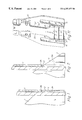
- FIG. 1 shows a guide element having a ramp surface with a steep inclination
- FIG. 2 shows a guide element having a ramp surface with a less steep inclination.
- FIGS. 1 and 2 show a stapler very schematically, the drive element 1 of the stapler being shown in its driving stroke, i.e. during the driving of a U-shaped staple 2 into a sheaf of papers (not shown). The lower edge surface of the drive element 1 then abuts against the web portion 2 b of the staple 2 .
- FIGS. 1 and 2 also show one guide element 3 of a guide means intended for internal guidance of the two legs 2 a of the staple 2 during the driving of the staple 2 .
- the guide element 3 is movable between a first position, in which it is inserted into the driving path of the staple 2 to abut against the inside of the corresponding staple leg 2 a, and a second position, in which it is removed against spring action from the driving path of the staple 2 .
- the guide element 3 has a ramp surface 4 facing upwards. During the driving of the staple 2 , its web portion 2 b abuts against the ramp surface 4 and then presses the guide element 3 from its first position to its second position (to the left in FIGS. 1 and 2) as the driving of the staple 2 proceeds.
- the ramp surface 4 of the guide element 3 shown in FIG. 1 has an inclination different from that of the ramp surface 4 of the guide element 3 shown in FIG. 2 .
- the steep inclination, shown in FIG. 1 gives the advantage of the extension of the guide element 3 in the moving direction of the guide element being fairly small, which results in the guide element 3 requiring a comparatively small space.
- the steep inclination gives, however, the disadvantage that a great deal of the upper portion of the staple leg 2 a, as is clearly shown in FIG. 1, does not obtain an internal support from the guide element 3 .
- the sheaf of papers is thick and exhibits a great resistance to the driving in of staples, it is important that the leg 2 a be guided over as much as possible of its length.
- a guide element 3 of the type shown in FIG. 2 must be used, i.e. a guide element whose ramp surface 4 has a less steep inclination.
- Such a guide element 3 offers, as is shown in FIG. 2, an internal support to the staple leg 2 a substantially over its entire length.
- the disadvantage of the less steep inclination is that the guide element 3 is given a large extent in the moving direction and thus takes up a great deal of space, especially as a space must be available for the movement of the guide element between its two positions.
- the object of the present invention is to provide a stapler, which is fitted with a guide means intended for internal guidance of the staple legs during the driving of the staple into an object, the guide means being of the type described above and its two guide elements offering an adequate support for the staple legs substantially over their entire length, while taking up a comparatively small space.
- this object is achieved by a stapler for driving staples into an object, such as a sheaf of papers, which stapler comprises a drive element arranged to expel a substantially U-shaped staple and drive its legs through said object, and a guide means for internal guidance of the legs of the staple during the driving of the staple into the object, which guide means is movable between a first position, in which it extends into the driving path of the staple to abut against the inside of the legs during the driving of the staple, and a second position, in which it is removed against spring action from the driving path of the staple, and which guide means has a ramp means for such cooperation with the web portion of the staple that the guide means is removed by the web portion against spring action to its second position as the driving of the staple proceeds, the guide means having two guide elements arranged to abut against the inside of a leg each during the driving of the staple, and which stapler is characterised in that each guide element consists of at least two substantially identical, separate guide parts successively arranged seen in the driving direction of
- each guide element consists of three separate parts.
- the parts of one guide element are each connected to one of the parts of the other guide element, each pair of interconnected parts forming the legs of a substantially U-shaped bracket.
- the brackets are advantageously formed at one end of a leaf spring each.
- FIGS. 1 and 2 show the guide elements described above for internal guidance of a staple leg
- FIGS. 3-6 are perspective views schematically showing a stapler according to the invention in different driving positions
- FIGS. 7, 8 , 9 and 10 are vertical section views showing a drive element, a guide element and a staple in different driving positions corresponding to the position shown in FIGS. 3, 4 , 5 and 6 , respectively, and
- FIG. 11 is a perspective view showing the guide element of the stapler from the opposite side in relation to FIGS. 3 - 6 .
- the stapler according to the invention illustrated in FIGS. 3-6, of which only a fraction is shown, has a drive element 11 for driving a substantially U-shaped staple 12 into a sheaf of papers 13 (cf. FIGS. 7 - 10 ).
- Two guide strips 14 for external guidance of the legs 12 a of the staple 12 during the driving of the staple into the sheaf of papers 13 are formed on a front plate 15 .
- the staple 12 is formed by bending a wire-shaped staple blank. This blank is contained in a magazine (not shown) together with a plurality of other staple blanks, from which magazine it is advanced to a staple forming position, in which the blank is formed to a substantially U-shaped staple 12 .
- the staple 12 thus formed is then advanced to its driving position just under the drive element 11 , i.e. slightly in front of (as related to FIGS. 3-6) the front plate 15 .
- the drive element 11 consists of a substantially rectangular metal sheet piece and is reciprocatingly arranged in the stapler in the direction of the double arrow P.
- the drive element 11 is reciprocatable between an upper initial position and a lower end position.
- the drive element 11 is shown in its driving stroke, i.e. in its movement from the initial position to the lower end position, its lower edge surface abutting against the back or web portion 12 b of the staple 12 .
- the drive element 11 drives the legs 12 a of the staple 12 into the sheaf of papers 13 and through the same with no deformation of the staple 12 , not even when the sheaf of papers is relatively thick or consists of rather hard sheets of paper.
- the drive element 11 has two projections 16 protruding from the lower edge surface of the drive element.
- the projections 16 are located at the same mutual distance as the legs 12 a of the staple 12 and are arranged to engage the web portion 12 b of the staple 12 just opposite a leg 12 a each of the staple 12 .
- the projections 16 are pointed in order to bite a distance into the web portion 12 b of the staple 12 in the engagement therewith.
- the stapler also has two guide elements 17 , 17 ′, 17 ′′ and 18 , 18 ′, 18 ′′ for internal guidance of the legs 12 a of the staple 12 during the driving of the staple into the sheaf of papers 13 .
- the two guide elements 17 , 17 ′, 17 ′′ and 18 , 18 ′, 18 ′′ extend from the back (as related to FIGS. 3-6) through a slot 19 , 20 each in the front plate 15 and protrude a distance in front thereof (as related to FIGS. 3 - 6 ).
- the two guide elements 17 , 17 ′, 17 ′′ and 18 , 18 ′, 18 ′′ each abut against a staple leg 12 a during the driving of the staple 12 .
- Each of the two guide elements consists of three substantially identical, separate guide parts 17 , 17 ′, 17 ′′ and 18 , 18 ′, 18 ′′, respectively, successively arranged seen in the driving direction of the staple 12 .
- the guide parts 17 , 17 ′ and 17 ′′ as well as the guide parts 18 , 18 ′ and 18 ′′ are arranged just above one another.
- the guide parts 17 , 17 ′ and 17 ′′ in one of the guide elements are arranged in horizontal alignment with a guide part 18 , 18 ′ and 18 ′′ each in the second guide element.
- the guide parts in each of these pairs 17 , 18 , 17 ′, 18 ′ and 17 ′′, 18 ′′ of such guide parts arranged in horizontal alignment are connected to each other so as to form the legs of a substantially U-shaped bracket 21 , 21 ′ and 21 ′′, respectively (cf. FIG. 11 ).
- These brackets 21 , 21 ′ and 21 ′′ are formed at one end of a leaf spring 22 , 22 ′ and 22 ′′ each.
- the leaf springs 22 , 22 ′ and 22 ′′ which have different length, are clamped behind the front plate 15 in a manner not shown in detail, such that the guide parts 17 , 18 , 17 ′, 18 ′, 17 ′′, 18 ′′ normally are located in the position shown in FIGS.
- the guide parts 17 , 18 , 17 ′, 18 ′, 17 ′′, 18 ′′ can be pressed in pairs against the spring action of the respective leaf springs 22 , 22 ′, 22 ′′ to a second position, in which they are fully removed from the driving path of the staple 12 .
- Each of the guide parts 17 , 17 ′, 17 ′′, 18 , 18 ′ and 18 ′′ has an upper horizontal edge surface, a lower vertical edge surface and an intermediate ramp surface 23 , 23 ′, 23 ′′, 24 , 24 ′ and 24 ′′, respectively, for cooperation with the web portion 12 b of the staple 12 .
- the stapler is shown in a driving position, in which the drive element 11 in its driving stroke has just engaged the web portion 12 b of the staple 12 to expel the staple 12 and drive it into the sheaf of papers 13 .
- the web portion 12 b is positioned a distance above the upper pair of guide parts 17 , 18 and the point of the staple legs 12 a has not yet reached the sheaf of papers 13 .
- the upper pair of guide parts 17 , 18 is in a fully moved-away position
- the intermediate pair of guide parts 17 ′, 18 ′ is in a partially moved-away position
- the staple legs 12 a have been driven a considerable distance into the sheaf of papers 13 .
- the upper and the intermediate pairs of guide parts 17 , 18 and 17 ′, 18 ′, respectively, are in a fully moved-away position
- the lower pair of guide parts 17 ′′, 18 ′′ is in a partially moved-away position
- the point of the staple legs 12 a has been driven through the sheaf of papers 13 , the web portion 12 b having, however, not yet reached the upper side of the sheaf of papers 13 .
- the driving stroke of the drive element 11 is completed and the lower pair of guide parts 17 ′′, 18 ′′ is also in a fully moved-away position.
Applications Claiming Priority (3)
| Application Number | Priority Date | Filing Date | Title |
|---|---|---|---|
| SE9701536A SE506725C2 (sv) | 1997-04-24 | 1997-04-24 | Häftapparat med invändig styrning av häftklammerskänklar |
| SE9701536 | 1997-04-24 | ||
| PCT/SE1998/000709 WO1998047669A1 (en) | 1997-04-24 | 1998-04-20 | Stapler with internal guidance of the legs of a staple |
Related Parent Applications (1)
| Application Number | Title | Priority Date | Filing Date |
|---|---|---|---|
| PCT/SE1998/000709 Continuation WO1998047669A1 (en) | 1997-04-24 | 1998-04-20 | Stapler with internal guidance of the legs of a staple |
Publications (1)
| Publication Number | Publication Date |
|---|---|
| US6257477B1 true US6257477B1 (en) | 2001-07-10 |
Family
ID=20406707
Family Applications (1)
| Application Number | Title | Priority Date | Filing Date |
|---|---|---|---|
| US09/425,889 Expired - Fee Related US6257477B1 (en) | 1997-04-24 | 1999-10-25 | Stapler with internal guidance of the legs of a staple |
Country Status (8)
| Country | Link |
|---|---|
| US (1) | US6257477B1 (ja) |
| EP (1) | EP1053080B1 (ja) |
| JP (1) | JP4085153B2 (ja) |
| CN (1) | CN1069568C (ja) |
| AU (1) | AU7353198A (ja) |
| DE (1) | DE69811405T2 (ja) |
| SE (1) | SE506725C2 (ja) |
| WO (1) | WO1998047669A1 (ja) |
Cited By (14)
| Publication number | Priority date | Publication date | Assignee | Title |
|---|---|---|---|---|
| US20030222116A1 (en) * | 2002-05-29 | 2003-12-04 | Chen Ming Hsien | Nail guiding mechanism of nailing gun |
| US6702172B1 (en) * | 1999-11-19 | 2004-03-09 | Isaberg Rapid Ab | Staple driver with convex edge and pointed protrusions at the ends |
| US20050224555A1 (en) * | 2004-04-02 | 2005-10-13 | Acco Brands, Inc. | Stapler with inside leg support |
| WO2005105397A1 (en) * | 2004-05-05 | 2005-11-10 | Isaberg Rapid Ab | Stapler |
| US20060186168A1 (en) * | 2003-08-01 | 2006-08-24 | Futoshi Kameda | Stapler |
| WO2008136726A1 (en) * | 2007-05-03 | 2008-11-13 | Isaberg Rapid Ab | Stapler |
| WO2009023841A1 (en) * | 2007-08-16 | 2009-02-19 | Accentra, Inc. | Staple leg guide |
| US20090293129A1 (en) * | 2008-05-24 | 2009-11-26 | Via Technologies, Inc | Termination of secure execution mode in a microprocessor providing for execution of secure code |
| US20100038400A1 (en) * | 2007-01-15 | 2010-02-18 | Charles Dale Ramsden | Aligning and locating device |
| US9016538B2 (en) | 2004-07-21 | 2015-04-28 | Charles Dale Ramsden | Corner device and corner device attachment kit |
| US20170217003A1 (en) * | 2016-02-03 | 2017-08-03 | Tsung-Wen Huang | Nail guiding device for nailer |
| US20180093370A1 (en) * | 2016-10-04 | 2018-04-05 | Stanley Black & Decker, Inc. | Fastening Tool with Contact Arm and Multi-Fastener Guide |
| US10603811B2 (en) * | 2016-10-31 | 2020-03-31 | Max Co., Ltd. | Stapler |
| US10814465B2 (en) | 2016-03-22 | 2020-10-27 | Stanley Black & Decker, Inc. | Safety device for tackers |
Families Citing this family (4)
| Publication number | Priority date | Publication date | Assignee | Title |
|---|---|---|---|---|
| SE515951C2 (sv) * | 2000-03-08 | 2001-10-29 | Isaberg Rapid Ab | Häftpistol för både klammer och spik med en fjädrande styranordning för spiken vid utskjutningsläget |
| JP4254149B2 (ja) * | 2002-07-26 | 2009-04-15 | マックス株式会社 | ホッチキスにおけるカートリッジ |
| JP5278735B2 (ja) * | 2008-07-24 | 2013-09-04 | 日立工機株式会社 | 打込機 |
| JP4752899B2 (ja) * | 2008-11-17 | 2011-08-17 | マックス株式会社 | ステープル打ち用釘打機 |
Citations (7)
| Publication number | Priority date | Publication date | Assignee | Title |
|---|---|---|---|---|
| US2086922A (en) * | 1936-02-15 | 1937-07-13 | Hotchkiss Co E H | Staple driving machine |
| US3009156A (en) * | 1956-05-18 | 1961-11-21 | Inv S Man Corp | Industrial tacker |
| US4431127A (en) | 1981-09-25 | 1984-02-14 | Kenji Watanabe | Apparatus for temporarily binding paper sheets |
| US4527725A (en) * | 1982-11-04 | 1985-07-09 | Minnesota Mining And Manufacturing Company | Stapler with retractable anvil |
| US4991763A (en) * | 1988-05-23 | 1991-02-12 | Technalytics Inc. | Surgical stapler |
| US5098002A (en) * | 1989-05-25 | 1992-03-24 | Ferag Ag | Stapling apparatus |
| US5452835A (en) * | 1994-08-01 | 1995-09-26 | Illinois Tool Works Inc. | Positioning mechanism for powered fastener-driving tool |
Family Cites Families (1)
| Publication number | Priority date | Publication date | Assignee | Title |
|---|---|---|---|---|
| SE137623C1 (ja) * |
-
1997
- 1997-04-24 SE SE9701536A patent/SE506725C2/sv not_active IP Right Cessation
-
1998
- 1998-04-20 AU AU73531/98A patent/AU7353198A/en not_active Abandoned
- 1998-04-20 WO PCT/SE1998/000709 patent/WO1998047669A1/en active IP Right Grant
- 1998-04-20 JP JP54559398A patent/JP4085153B2/ja not_active Expired - Lifetime
- 1998-04-20 CN CN98805485A patent/CN1069568C/zh not_active Expired - Fee Related
- 1998-04-20 DE DE69811405T patent/DE69811405T2/de not_active Expired - Lifetime
- 1998-04-20 EP EP98920767A patent/EP1053080B1/en not_active Expired - Lifetime
-
1999
- 1999-10-25 US US09/425,889 patent/US6257477B1/en not_active Expired - Fee Related
Patent Citations (7)
| Publication number | Priority date | Publication date | Assignee | Title |
|---|---|---|---|---|
| US2086922A (en) * | 1936-02-15 | 1937-07-13 | Hotchkiss Co E H | Staple driving machine |
| US3009156A (en) * | 1956-05-18 | 1961-11-21 | Inv S Man Corp | Industrial tacker |
| US4431127A (en) | 1981-09-25 | 1984-02-14 | Kenji Watanabe | Apparatus for temporarily binding paper sheets |
| US4527725A (en) * | 1982-11-04 | 1985-07-09 | Minnesota Mining And Manufacturing Company | Stapler with retractable anvil |
| US4991763A (en) * | 1988-05-23 | 1991-02-12 | Technalytics Inc. | Surgical stapler |
| US5098002A (en) * | 1989-05-25 | 1992-03-24 | Ferag Ag | Stapling apparatus |
| US5452835A (en) * | 1994-08-01 | 1995-09-26 | Illinois Tool Works Inc. | Positioning mechanism for powered fastener-driving tool |
Cited By (21)
| Publication number | Priority date | Publication date | Assignee | Title |
|---|---|---|---|---|
| US6702172B1 (en) * | 1999-11-19 | 2004-03-09 | Isaberg Rapid Ab | Staple driver with convex edge and pointed protrusions at the ends |
| US20030222116A1 (en) * | 2002-05-29 | 2003-12-04 | Chen Ming Hsien | Nail guiding mechanism of nailing gun |
| US20060186168A1 (en) * | 2003-08-01 | 2006-08-24 | Futoshi Kameda | Stapler |
| US20050224555A1 (en) * | 2004-04-02 | 2005-10-13 | Acco Brands, Inc. | Stapler with inside leg support |
| WO2005105397A1 (en) * | 2004-05-05 | 2005-11-10 | Isaberg Rapid Ab | Stapler |
| US20080265000A1 (en) * | 2004-05-05 | 2008-10-30 | Isberg Rapid Ab | Stapler |
| CN100436088C (zh) * | 2004-05-05 | 2008-11-26 | 伊萨贝格雷玻德股份公司 | 订u形钉机 |
| US7726535B2 (en) | 2004-05-05 | 2010-06-01 | Isaberg Rapid Ab | Stapler |
| US9016538B2 (en) | 2004-07-21 | 2015-04-28 | Charles Dale Ramsden | Corner device and corner device attachment kit |
| US20100038400A1 (en) * | 2007-01-15 | 2010-02-18 | Charles Dale Ramsden | Aligning and locating device |
| WO2008136726A1 (en) * | 2007-05-03 | 2008-11-13 | Isaberg Rapid Ab | Stapler |
| US20090045238A1 (en) * | 2007-08-16 | 2009-02-19 | Accentra, Inc. | Staple leg guide |
| WO2009023841A1 (en) * | 2007-08-16 | 2009-02-19 | Accentra, Inc. | Staple leg guide |
| US7731071B2 (en) | 2007-08-16 | 2010-06-08 | Accentra, Inc. | Staple leg guide |
| US20090293129A1 (en) * | 2008-05-24 | 2009-11-26 | Via Technologies, Inc | Termination of secure execution mode in a microprocessor providing for execution of secure code |
| US20170217003A1 (en) * | 2016-02-03 | 2017-08-03 | Tsung-Wen Huang | Nail guiding device for nailer |
| US10022849B2 (en) * | 2016-02-03 | 2018-07-17 | Tsung-Wen Huang | Nail guiding device for nailer |
| US10814465B2 (en) | 2016-03-22 | 2020-10-27 | Stanley Black & Decker, Inc. | Safety device for tackers |
| US11633839B2 (en) | 2016-03-22 | 2023-04-25 | Stanley Black & Decker, Inc. | Safety device for tackers |
| US20180093370A1 (en) * | 2016-10-04 | 2018-04-05 | Stanley Black & Decker, Inc. | Fastening Tool with Contact Arm and Multi-Fastener Guide |
| US10603811B2 (en) * | 2016-10-31 | 2020-03-31 | Max Co., Ltd. | Stapler |
Also Published As
| Publication number | Publication date |
|---|---|
| DE69811405D1 (de) | 2003-03-20 |
| WO1998047669A1 (en) | 1998-10-29 |
| DE69811405T2 (de) | 2004-01-08 |
| CN1069568C (zh) | 2001-08-15 |
| SE9701536D0 (sv) | 1997-04-24 |
| SE9701536L (sv) | 1998-02-02 |
| CN1257440A (zh) | 2000-06-21 |
| AU7353198A (en) | 1998-11-13 |
| JP4085153B2 (ja) | 2008-05-14 |
| EP1053080A1 (en) | 2000-11-22 |
| EP1053080B1 (en) | 2003-02-12 |
| JP2001524881A (ja) | 2001-12-04 |
| SE506725C2 (sv) | 1998-02-02 |
Similar Documents
| Publication | Publication Date | Title |
|---|---|---|
| US6257477B1 (en) | Stapler with internal guidance of the legs of a staple | |
| US5516025A (en) | Stapler having a clinching mechanism | |
| JP3598765B2 (ja) | ホッチキスにおけるステープルのクリンチ機構 | |
| US7665645B2 (en) | Stapler | |
| US4463890A (en) | Staplers | |
| JP4082251B2 (ja) | ステープラーのクリンチャ装置 | |
| US7621433B2 (en) | Stapler | |
| EP0636059B1 (en) | Stapler | |
| US6702172B1 (en) | Staple driver with convex edge and pointed protrusions at the ends | |
| EP0027336B1 (en) | Passive clincher and stapler incorporating same | |
| US4366924A (en) | Stapler having an abutment for limiting stapler repenetration | |
| JP4417645B2 (ja) | ステープル成形装置 | |
| US2289308A (en) | Stapling machine | |
| US2308611A (en) | Stapling machine | |
| US6986449B2 (en) | Staple-former in a stapler | |
| WO2004002697A1 (ja) | 電動ステープラ | |
| JP4093155B2 (ja) | ステープラー用のクリンチャ装置 | |
| JP4089214B2 (ja) | ステープラにおける用紙基準の移動機構 | |
| WO2008030153A1 (en) | Feed means in a staple cassette intended for a stapler | |
| JP4650611B2 (ja) | ステープラーのクリンチャ機構 | |
| WO2009029042A1 (en) | Feed member for a staple magazine of a stapler in order to prevent jamming | |
| JPH0653075U (ja) | 電動ホッチキスにおけるマガジン作動案内装置 |
Legal Events
| Date | Code | Title | Description |
|---|---|---|---|
| AS | Assignment |
Owner name: ISABERG RAPID AB, SWEDEN Free format text: ASSIGNMENT OF ASSIGNORS INTEREST;ASSIGNORS:STRAAT, OLLE;GUSTAFSSON, TRYGVE;REEL/FRAME:010556/0227 Effective date: 20000110 |
|
| AS | Assignment |
Owner name: ISABERG RAPID AB, SWEDEN Free format text: ASSIGNMENT OF ASSIGNORS INTEREST;ASSIGNORS:STRAAT, OLLE;GUSTAFSSON, TRYGVE;REEL/FRAME:010817/0727 Effective date: 20000303 |
|
| FPAY | Fee payment |
Year of fee payment: 4 |
|
| FEPP | Fee payment procedure |
Free format text: PAYOR NUMBER ASSIGNED (ORIGINAL EVENT CODE: ASPN); ENTITY STATUS OF PATENT OWNER: LARGE ENTITY |
|
| FPAY | Fee payment |
Year of fee payment: 8 |
|
| FEPP | Fee payment procedure |
Free format text: PAYER NUMBER DE-ASSIGNED (ORIGINAL EVENT CODE: RMPN); ENTITY STATUS OF PATENT OWNER: LARGE ENTITY Free format text: PAYOR NUMBER ASSIGNED (ORIGINAL EVENT CODE: ASPN); ENTITY STATUS OF PATENT OWNER: LARGE ENTITY |
|
| REMI | Maintenance fee reminder mailed | ||
| LAPS | Lapse for failure to pay maintenance fees | ||
| STCH | Information on status: patent discontinuation |
Free format text: PATENT EXPIRED DUE TO NONPAYMENT OF MAINTENANCE FEES UNDER 37 CFR 1.362 |
|
| FP | Lapsed due to failure to pay maintenance fee |
Effective date: 20130710 |