US6173573B1 - Control device for hydraulic drive machine - Google Patents
Control device for hydraulic drive machine Download PDFInfo
- Publication number
- US6173573B1 US6173573B1 US09/125,691 US12569198A US6173573B1 US 6173573 B1 US6173573 B1 US 6173573B1 US 12569198 A US12569198 A US 12569198A US 6173573 B1 US6173573 B1 US 6173573B1
- Authority
- US
- United States
- Prior art keywords
- pressure
- differential pressure
- operating
- hydraulic
- control
- Prior art date
- Legal status (The legal status is an assumption and is not a legal conclusion. Google has not performed a legal analysis and makes no representation as to the accuracy of the status listed.)
- Expired - Fee Related
Links
Images


Classifications
-
- F—MECHANICAL ENGINEERING; LIGHTING; HEATING; WEAPONS; BLASTING
- F15—FLUID-PRESSURE ACTUATORS; HYDRAULICS OR PNEUMATICS IN GENERAL
- F15B—SYSTEMS ACTING BY MEANS OF FLUIDS IN GENERAL; FLUID-PRESSURE ACTUATORS, e.g. SERVOMOTORS; DETAILS OF FLUID-PRESSURE SYSTEMS, NOT OTHERWISE PROVIDED FOR
- F15B11/00—Servomotor systems without provision for follow-up action; Circuits therefor
- F15B11/16—Servomotor systems without provision for follow-up action; Circuits therefor with two or more servomotors
- F15B11/161—Servomotor systems without provision for follow-up action; Circuits therefor with two or more servomotors with sensing of servomotor demand or load
- F15B11/163—Servomotor systems without provision for follow-up action; Circuits therefor with two or more servomotors with sensing of servomotor demand or load for sharing the pump output equally amongst users or groups of users, e.g. using anti-saturation, pressure compensation
-
- B—PERFORMING OPERATIONS; TRANSPORTING
- B60—VEHICLES IN GENERAL
- B60R—VEHICLES, VEHICLE FITTINGS, OR VEHICLE PARTS, NOT OTHERWISE PROVIDED FOR
- B60R16/00—Electric or fluid circuits specially adapted for vehicles and not otherwise provided for; Arrangement of elements of electric or fluid circuits specially adapted for vehicles and not otherwise provided for
- B60R16/02—Electric or fluid circuits specially adapted for vehicles and not otherwise provided for; Arrangement of elements of electric or fluid circuits specially adapted for vehicles and not otherwise provided for electric constitutive elements
- B60R16/03—Electric or fluid circuits specially adapted for vehicles and not otherwise provided for; Arrangement of elements of electric or fluid circuits specially adapted for vehicles and not otherwise provided for electric constitutive elements for supply of electrical power to vehicle subsystems or for
- B60R16/0315—Electric or fluid circuits specially adapted for vehicles and not otherwise provided for; Arrangement of elements of electric or fluid circuits specially adapted for vehicles and not otherwise provided for electric constitutive elements for supply of electrical power to vehicle subsystems or for using multiplexing techniques
-
- F—MECHANICAL ENGINEERING; LIGHTING; HEATING; WEAPONS; BLASTING
- F15—FLUID-PRESSURE ACTUATORS; HYDRAULICS OR PNEUMATICS IN GENERAL
- F15B—SYSTEMS ACTING BY MEANS OF FLUIDS IN GENERAL; FLUID-PRESSURE ACTUATORS, e.g. SERVOMOTORS; DETAILS OF FLUID-PRESSURE SYSTEMS, NOT OTHERWISE PROVIDED FOR
- F15B11/00—Servomotor systems without provision for follow-up action; Circuits therefor
- F15B11/16—Servomotor systems without provision for follow-up action; Circuits therefor with two or more servomotors
- F15B11/161—Servomotor systems without provision for follow-up action; Circuits therefor with two or more servomotors with sensing of servomotor demand or load
- F15B11/166—Controlling a pilot pressure in response to the load, i.e. supply to at least one user is regulated by adjusting either the system pilot pressure or one or more of the individual pilot command pressures
-
- F—MECHANICAL ENGINEERING; LIGHTING; HEATING; WEAPONS; BLASTING
- F15—FLUID-PRESSURE ACTUATORS; HYDRAULICS OR PNEUMATICS IN GENERAL
- F15B—SYSTEMS ACTING BY MEANS OF FLUIDS IN GENERAL; FLUID-PRESSURE ACTUATORS, e.g. SERVOMOTORS; DETAILS OF FLUID-PRESSURE SYSTEMS, NOT OTHERWISE PROVIDED FOR
- F15B21/00—Common features of fluid actuator systems; Fluid-pressure actuator systems or details thereof, not covered by any other group of this subclass
- F15B21/08—Servomotor systems incorporating electrically operated control means
- F15B21/087—Control strategy, e.g. with block diagram
-
- B—PERFORMING OPERATIONS; TRANSPORTING
- B60—VEHICLES IN GENERAL
- B60R—VEHICLES, VEHICLE FITTINGS, OR VEHICLE PARTS, NOT OTHERWISE PROVIDED FOR
- B60R16/00—Electric or fluid circuits specially adapted for vehicles and not otherwise provided for; Arrangement of elements of electric or fluid circuits specially adapted for vehicles and not otherwise provided for
- B60R16/02—Electric or fluid circuits specially adapted for vehicles and not otherwise provided for; Arrangement of elements of electric or fluid circuits specially adapted for vehicles and not otherwise provided for electric constitutive elements
- B60R16/03—Electric or fluid circuits specially adapted for vehicles and not otherwise provided for; Arrangement of elements of electric or fluid circuits specially adapted for vehicles and not otherwise provided for electric constitutive elements for supply of electrical power to vehicle subsystems or for
- B60R16/0315—Electric or fluid circuits specially adapted for vehicles and not otherwise provided for; Arrangement of elements of electric or fluid circuits specially adapted for vehicles and not otherwise provided for electric constitutive elements for supply of electrical power to vehicle subsystems or for using multiplexing techniques
- B60R2016/0322—Temporary code for documents to be reclassified to G08C, H04L or H04Q
-
- F—MECHANICAL ENGINEERING; LIGHTING; HEATING; WEAPONS; BLASTING
- F15—FLUID-PRESSURE ACTUATORS; HYDRAULICS OR PNEUMATICS IN GENERAL
- F15B—SYSTEMS ACTING BY MEANS OF FLUIDS IN GENERAL; FLUID-PRESSURE ACTUATORS, e.g. SERVOMOTORS; DETAILS OF FLUID-PRESSURE SYSTEMS, NOT OTHERWISE PROVIDED FOR
- F15B2211/00—Circuits for servomotor systems
- F15B2211/20—Fluid pressure source, e.g. accumulator or variable axial piston pump
- F15B2211/205—Systems with pumps
- F15B2211/2053—Type of pump
- F15B2211/20546—Type of pump variable capacity
- F15B2211/20553—Type of pump variable capacity with pilot circuit, e.g. for controlling a swash plate
-
- F—MECHANICAL ENGINEERING; LIGHTING; HEATING; WEAPONS; BLASTING
- F15—FLUID-PRESSURE ACTUATORS; HYDRAULICS OR PNEUMATICS IN GENERAL
- F15B—SYSTEMS ACTING BY MEANS OF FLUIDS IN GENERAL; FLUID-PRESSURE ACTUATORS, e.g. SERVOMOTORS; DETAILS OF FLUID-PRESSURE SYSTEMS, NOT OTHERWISE PROVIDED FOR
- F15B2211/00—Circuits for servomotor systems
- F15B2211/30—Directional control
- F15B2211/31—Directional control characterised by the positions of the valve element
- F15B2211/3105—Neutral or centre positions
- F15B2211/3111—Neutral or centre positions the pump port being closed in the centre position, e.g. so-called closed centre
-
- F—MECHANICAL ENGINEERING; LIGHTING; HEATING; WEAPONS; BLASTING
- F15—FLUID-PRESSURE ACTUATORS; HYDRAULICS OR PNEUMATICS IN GENERAL
- F15B—SYSTEMS ACTING BY MEANS OF FLUIDS IN GENERAL; FLUID-PRESSURE ACTUATORS, e.g. SERVOMOTORS; DETAILS OF FLUID-PRESSURE SYSTEMS, NOT OTHERWISE PROVIDED FOR
- F15B2211/00—Circuits for servomotor systems
- F15B2211/30—Directional control
- F15B2211/32—Directional control characterised by the type of actuation
- F15B2211/327—Directional control characterised by the type of actuation electrically or electronically
-
- F—MECHANICAL ENGINEERING; LIGHTING; HEATING; WEAPONS; BLASTING
- F15—FLUID-PRESSURE ACTUATORS; HYDRAULICS OR PNEUMATICS IN GENERAL
- F15B—SYSTEMS ACTING BY MEANS OF FLUIDS IN GENERAL; FLUID-PRESSURE ACTUATORS, e.g. SERVOMOTORS; DETAILS OF FLUID-PRESSURE SYSTEMS, NOT OTHERWISE PROVIDED FOR
- F15B2211/00—Circuits for servomotor systems
- F15B2211/60—Circuit components or control therefor
- F15B2211/63—Electronic controllers
- F15B2211/6303—Electronic controllers using input signals
- F15B2211/6306—Electronic controllers using input signals representing a pressure
- F15B2211/6309—Electronic controllers using input signals representing a pressure the pressure being a pressure source supply pressure
-
- F—MECHANICAL ENGINEERING; LIGHTING; HEATING; WEAPONS; BLASTING
- F15—FLUID-PRESSURE ACTUATORS; HYDRAULICS OR PNEUMATICS IN GENERAL
- F15B—SYSTEMS ACTING BY MEANS OF FLUIDS IN GENERAL; FLUID-PRESSURE ACTUATORS, e.g. SERVOMOTORS; DETAILS OF FLUID-PRESSURE SYSTEMS, NOT OTHERWISE PROVIDED FOR
- F15B2211/00—Circuits for servomotor systems
- F15B2211/60—Circuit components or control therefor
- F15B2211/63—Electronic controllers
- F15B2211/6303—Electronic controllers using input signals
- F15B2211/6306—Electronic controllers using input signals representing a pressure
- F15B2211/6313—Electronic controllers using input signals representing a pressure the pressure being a load pressure
-
- F—MECHANICAL ENGINEERING; LIGHTING; HEATING; WEAPONS; BLASTING
- F15—FLUID-PRESSURE ACTUATORS; HYDRAULICS OR PNEUMATICS IN GENERAL
- F15B—SYSTEMS ACTING BY MEANS OF FLUIDS IN GENERAL; FLUID-PRESSURE ACTUATORS, e.g. SERVOMOTORS; DETAILS OF FLUID-PRESSURE SYSTEMS, NOT OTHERWISE PROVIDED FOR
- F15B2211/00—Circuits for servomotor systems
- F15B2211/60—Circuit components or control therefor
- F15B2211/63—Electronic controllers
- F15B2211/6303—Electronic controllers using input signals
- F15B2211/633—Electronic controllers using input signals representing a state of the prime mover, e.g. torque or rotational speed
-
- F—MECHANICAL ENGINEERING; LIGHTING; HEATING; WEAPONS; BLASTING
- F15—FLUID-PRESSURE ACTUATORS; HYDRAULICS OR PNEUMATICS IN GENERAL
- F15B—SYSTEMS ACTING BY MEANS OF FLUIDS IN GENERAL; FLUID-PRESSURE ACTUATORS, e.g. SERVOMOTORS; DETAILS OF FLUID-PRESSURE SYSTEMS, NOT OTHERWISE PROVIDED FOR
- F15B2211/00—Circuits for servomotor systems
- F15B2211/60—Circuit components or control therefor
- F15B2211/63—Electronic controllers
- F15B2211/6303—Electronic controllers using input signals
- F15B2211/6346—Electronic controllers using input signals representing a state of input means, e.g. joystick position
-
- F—MECHANICAL ENGINEERING; LIGHTING; HEATING; WEAPONS; BLASTING
- F15—FLUID-PRESSURE ACTUATORS; HYDRAULICS OR PNEUMATICS IN GENERAL
- F15B—SYSTEMS ACTING BY MEANS OF FLUIDS IN GENERAL; FLUID-PRESSURE ACTUATORS, e.g. SERVOMOTORS; DETAILS OF FLUID-PRESSURE SYSTEMS, NOT OTHERWISE PROVIDED FOR
- F15B2211/00—Circuits for servomotor systems
- F15B2211/60—Circuit components or control therefor
- F15B2211/665—Methods of control using electronic components
- F15B2211/6651—Control of the prime mover, e.g. control of the output torque or rotational speed
-
- F—MECHANICAL ENGINEERING; LIGHTING; HEATING; WEAPONS; BLASTING
- F15—FLUID-PRESSURE ACTUATORS; HYDRAULICS OR PNEUMATICS IN GENERAL
- F15B—SYSTEMS ACTING BY MEANS OF FLUIDS IN GENERAL; FLUID-PRESSURE ACTUATORS, e.g. SERVOMOTORS; DETAILS OF FLUID-PRESSURE SYSTEMS, NOT OTHERWISE PROVIDED FOR
- F15B2211/00—Circuits for servomotor systems
- F15B2211/60—Circuit components or control therefor
- F15B2211/665—Methods of control using electronic components
- F15B2211/6652—Control of the pressure source, e.g. control of the swash plate angle
-
- F—MECHANICAL ENGINEERING; LIGHTING; HEATING; WEAPONS; BLASTING
- F15—FLUID-PRESSURE ACTUATORS; HYDRAULICS OR PNEUMATICS IN GENERAL
- F15B—SYSTEMS ACTING BY MEANS OF FLUIDS IN GENERAL; FLUID-PRESSURE ACTUATORS, e.g. SERVOMOTORS; DETAILS OF FLUID-PRESSURE SYSTEMS, NOT OTHERWISE PROVIDED FOR
- F15B2211/00—Circuits for servomotor systems
- F15B2211/60—Circuit components or control therefor
- F15B2211/665—Methods of control using electronic components
- F15B2211/6654—Flow rate control
-
- F—MECHANICAL ENGINEERING; LIGHTING; HEATING; WEAPONS; BLASTING
- F15—FLUID-PRESSURE ACTUATORS; HYDRAULICS OR PNEUMATICS IN GENERAL
- F15B—SYSTEMS ACTING BY MEANS OF FLUIDS IN GENERAL; FLUID-PRESSURE ACTUATORS, e.g. SERVOMOTORS; DETAILS OF FLUID-PRESSURE SYSTEMS, NOT OTHERWISE PROVIDED FOR
- F15B2211/00—Circuits for servomotor systems
- F15B2211/60—Circuit components or control therefor
- F15B2211/67—Methods for controlling pilot pressure
-
- F—MECHANICAL ENGINEERING; LIGHTING; HEATING; WEAPONS; BLASTING
- F15—FLUID-PRESSURE ACTUATORS; HYDRAULICS OR PNEUMATICS IN GENERAL
- F15B—SYSTEMS ACTING BY MEANS OF FLUIDS IN GENERAL; FLUID-PRESSURE ACTUATORS, e.g. SERVOMOTORS; DETAILS OF FLUID-PRESSURE SYSTEMS, NOT OTHERWISE PROVIDED FOR
- F15B2211/00—Circuits for servomotor systems
- F15B2211/70—Output members, e.g. hydraulic motors or cylinders or control therefor
- F15B2211/705—Output members, e.g. hydraulic motors or cylinders or control therefor characterised by the type of output members or actuators
- F15B2211/7051—Linear output members
- F15B2211/7053—Double-acting output members
-
- F—MECHANICAL ENGINEERING; LIGHTING; HEATING; WEAPONS; BLASTING
- F15—FLUID-PRESSURE ACTUATORS; HYDRAULICS OR PNEUMATICS IN GENERAL
- F15B—SYSTEMS ACTING BY MEANS OF FLUIDS IN GENERAL; FLUID-PRESSURE ACTUATORS, e.g. SERVOMOTORS; DETAILS OF FLUID-PRESSURE SYSTEMS, NOT OTHERWISE PROVIDED FOR
- F15B2211/00—Circuits for servomotor systems
- F15B2211/70—Output members, e.g. hydraulic motors or cylinders or control therefor
- F15B2211/71—Multiple output members, e.g. multiple hydraulic motors or cylinders
-
- F—MECHANICAL ENGINEERING; LIGHTING; HEATING; WEAPONS; BLASTING
- F15—FLUID-PRESSURE ACTUATORS; HYDRAULICS OR PNEUMATICS IN GENERAL
- F15B—SYSTEMS ACTING BY MEANS OF FLUIDS IN GENERAL; FLUID-PRESSURE ACTUATORS, e.g. SERVOMOTORS; DETAILS OF FLUID-PRESSURE SYSTEMS, NOT OTHERWISE PROVIDED FOR
- F15B2211/00—Circuits for servomotor systems
- F15B2211/70—Output members, e.g. hydraulic motors or cylinders or control therefor
- F15B2211/75—Control of speed of the output member
-
- F—MECHANICAL ENGINEERING; LIGHTING; HEATING; WEAPONS; BLASTING
- F15—FLUID-PRESSURE ACTUATORS; HYDRAULICS OR PNEUMATICS IN GENERAL
- F15B—SYSTEMS ACTING BY MEANS OF FLUIDS IN GENERAL; FLUID-PRESSURE ACTUATORS, e.g. SERVOMOTORS; DETAILS OF FLUID-PRESSURE SYSTEMS, NOT OTHERWISE PROVIDED FOR
- F15B2211/00—Circuits for servomotor systems
- F15B2211/70—Output members, e.g. hydraulic motors or cylinders or control therefor
- F15B2211/78—Control of multiple output members
Definitions
- the present invention relates to a control device, which drives and controls a hydraulic actuator in accordance with the control input of a operating member in a hydraulic drive machine, such as an hydraulic excavator, or crane.
- hydraulic drive machines such as construction equipment, are configured so that a drive command signal, which specifies a control input for a plurality of operating levers, is applied to a plurality of corresponding operating valves (flow control valves).
- the above drive command signal changes the areas of the apertures of these plurality of operating valves, thereby driving a corresponding plurality of hydraulic actuators.
- pressure oil discharged by a hydraulic pump is supplied to a plurality of hydraulic actuators via a plurality of operating valves on a plurality of pressure oil supply channels, and these plurality of hydraulic actuators are driven simultaneously.
- a valve called a pressure compensation valve, is provided either between a hydraulic pump and a flow control valve, or between a flow control valve and a hydraulic actuator, and works to compensate for the differential pressure of pressure across a valve for pressure oil, which flows through a flow control valve, so that this differential pressure is the same value for all drive shafts (In construction equipment, a drive shaft refers to a boom, arm, et cetera.). That is, in the general formula for a hydraulic circuit,
- the load sensing system works to achieve a flow Q, which is proportional to an operator-ordered drive command value (aperture area A) by making the differential pressure ⁇ P the same for each drive shaft.
- the load sensing system works to control the discharge pressure of the hydraulic pump so that the discharge pressure of the hydraulic pump achieves a pressure whereby the above across-valve differential pressure is added to the maximum value of the load of the operating hydraulic actuators. This prevents changes in velocity (load dependency) resulting from differences in the load of each hydraulic actuator when operated in combination.
- Japanese Patent Publication No. 6-41762 and Japanese Patent Publication No. 6-41764 propose the configuration of a system that does not utilize the above-mentioned pressure compensation valve.
- the square root of the ratio between a differential pressure set in advance and the detected value of the differential pressure across a flow control valve is used as the correction factor to compensate for the drive command value (control input from an operating lever) for pertinent flow control valves of drive shafts other than the drive shaft with a minimum differential pressure across the flow control valve.
- pump load sensing control is essential so that the differential pressure between the discharge pressure of the hydraulic pump and the maximum load pressure of the plurality of hydraulic actuators (minimum differential pressure) becomes the differential pressure that was set in advance.
- mini differential pressure the differential pressure between the discharge pressure of the hydraulic pump and the maximum load pressure of the plurality of hydraulic actuators.
- the idea is to digitize a conventional load sensing system as-is, and to deal with a small differential pressure by shutting off control.
- the invention of the present application takes these facts into consideration, and has as a first object to make do with a simple hydraulic circuit, which does not utilize a pressure compensation valve, and to enable the use of an inexpensive, low precision pressure detector, to enable the maintenance of continuous control at all times using simple controls, and to get by without shocking the operator or the mechanical parts, and to cancel the load dependency of a hydraulic actuator flow during combined operation without limiting the control system of the hydraulic pump.
- the speed of the light load working machine is required more than split control in accordance with the control input of the operating lever.
- What is required is believed to be a “load-bearing” split, that is, control that weakens pressure compensation.
- an operation performed frequently during hydraulic excavator work is “rough-combing” whereby the surface of the ground is leveled.
- an operator prefers to move the cutting edge of the bucket roughly horizontally over the surface of the ground using a full-lever boom-up, arm-excavation operation. If there is no pressure compensation at this point, because there is little pressure for raising the boom, the cutting edge of the bucket moves roughly horizontally over the ground. But when all-out pressure compensation is applied, it gives rise to the problem of the trajectory of the cutting edge of the bucket rising high into a circular arc.
- the present invention takes this fact into consideration, and has as a second object enhancing lever controllability, and improving work efficiency by making it possible to change pressure compensation characteristics of a hydraulic actuator in accordance with operating lever operating status and load pressure.
- a first invention of the present invention is a control device for a hydraulic drive machine which comprises a hydraulic pump, a plurality of hydraulic actuators provided in correspondence with a plurality of operating members, and a plurality of operating valves for supplying to corresponding hydraulic actuators a pressure oil discharged from the hydraulic pump at a flow rate that accords with control inputs of the operating members, and which drives the hydraulic actuators in accordance with the operation of the operating members, characterized in that the control device comprises:
- differential pressure detection means for detecting for each operating valve a differential pressure between a pressure of the pressure oil flowing into the operating valve and a pressure of the pressure oil flowing out of the operating valve;
- minimum differential pressure selection means for selecting a minimum differential pressure from among the differential pressures detected by the differential pressure detection means
- correction factor calculation means for calculating for each operating member a correction factor for correcting, on the basis of a ratio between the detected differential pressure of the operating valve and the selected minimum differential pressure, a control input of an operating member corresponding to the operating valve;
- control input correction means for correcting the control input of a corresponding operating member using the correction factor calculated by the correction factor calculation means.
- a correction factor for correcting the control input of an operating member that corresponds to this operating valve is calculated for each operating member on the basis of the ratio between the detected differential pressure across an operating valve and a minimum differential pressure selected from among the differential pressures across a plurality of operating valves. And the control input of a corresponding operating member is corrected using this calculated correction factor.
- the flow Qi supplied to the ith hydraulic actuator is determined solely by the size of the aperture area command value Ai.
- the numerator when division is performed using a number near zero (when the detected differential pressure is the minimum differential pressure), the numerator is also the minimum differential pressure, so the quotient is always 1, and errors contained in a detection error offset one another. Conversely, even when division is performed using a detected differential pressure other than the minimum differential pressure, because the detected differential pressure denominator is larger than the minimum differential pressure numerator, the process is completed with little impact from detection errors. That is, because better-than-constant precision can be ensured even using an inexpensive, low-precision pressure detector, cost reducing effects can be achieved.
- control is performed using a compensation calculation that divides the minimum differential pressure by the detected pressure ⁇ P at each operating valve without having to switch from compensation calculation-based control to ordinary control each time there is a switchover to a drive shaft with the minimum across-valve differential pressure.
- the drive command values to a hydraulic actuator are continuous during the instant of control switchover, thus solving for the past problem of a shock being generated at each switchover. This achieves the effect whereby control continuity can be maintained via simple control, and the operator and machine parts are not shocked.
- a second invention of the present invention is a control device for a hydraulic drive machine which comprises a hydraulic pump, a plurality of hydraulic actuators provided in correspondence with a plurality of operating members, and a plurality of operating valves for supplying to corresponding hydraulic actuators a pressure oil discharged from the hydraulic pump at a flow rate that accords with control inputs of the operating members, and which drives the hydraulic actuators in accordance with the operation of the operating members, characterized in that the control device comprises:
- differential pressure detection means for detecting for each operating valve a differential pressure between a pressure of the pressure oil flowing into the operating valve and a pressure of the pressure oil flowing out of the operating valve;
- correction factor calculation means for calculating for each operating member a correction factor for correcting the control input of the operating member in accordance with the differential pressure detected by the differential pressure detection means;
- setting means for setting for each operating member an upper limit value or a lower limit value of the correction factor in accordance with the control input of the operating member;
- control input correction means for correcting the control input of a corresponding operating member, using a correction factor of which upper limit or lower limit is limited, so that the correction factor calculated by the correction factor calculation means does not exceed the set upper limit value or lower limit value.
- an upper limit value or lower limit value of the correction factor is set for each operating member in accordance with the control input of the operating member, making it so that a correction factor obtained in accordance with a detected differential pressure does not exceed the above-mentioned set upper limit value of lower limit value, and the control input of a corresponding operating member is corrected using a correction factor, which is limited by this upper limit or lower limit.
- the pressure compensation function is weakened, and the large incoming flow to a hydraulic actuator with a light load is not controlled.
- the present invention improves controllability at full-lever operation, and work efficiency is enhanced pursuant thereto.
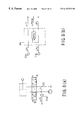
- FIG. 1 is a diagram, which shows a configuration of an embodiment of a control device for a hydraulic drive machine related to the present invention, and which shows the configuration at a flow control valve when detecting across-valve differential pressure at the side where flow enters a hydraulic cylinder;
- FIG. 2 is a block diagram showing a configuration of the controller depicted in FIG. 1;
- FIGS. 3 ( a ), ( b ) are diagrams showing examples of other configurations of the pressure sensor depicted in FIG. 1;
- FIGS. 4 ( a ), ( b ) are block diagrams showing examples of configurations of controllers corresponding to FIGS. 3 ( a ), ( b ), respectively;
- FIGS. 5 ( a ), ( b ) are block diagrams showing examples of configurations wherein a flow control valve is being operated using feedback control;
- FIG. 6 is a diagram, which shows a configuration of an embodiment of a control device for a hydraulic drive machine related to the present invention, and which shows the configuration at a flow control valve when detecting across-valve differential pressure at the side where flow exits to a tank;
- FIG. 7 is a block diagram showing a configuration of the controller depicted in FIG. 6;
- FIGS. 8 ( a ), ( b ) is a diagram showing another example of the pressure sensor depicted in FIG. 6, and a block diagram showing an example of a configuration for a controller corresponding thereto;
- FIG. 9 is a diagram, which shows a configuration of an embodiment of a control device for a hydraulic drive machine related to the present invention, and which shows the configuration when an operating lever is utilized as a hydraulic lever;
- FIG. 10 is a block diagram showing the configuration of the controller depicted in FIG. 9;
- FIGS. 11 ( a ), ( b ) are block diagrams used to describe hydraulic pump control
- FIGS. 12 ( a ), ( b ) are block diagrams used to describe another hydraulic pump control
- FIGS. 13 ( a ), ( b ) are block diagrams used to describe yet another hydraulic pump control
- FIGS. 14 ( a ), ( b ) is a diagram showing a configuration of an embodiment of a control device for a hydraulic drive machine related to the present invention, and a diagram showing the configuration when the degree of pressure compensation is varied;
- FIG. 15 is a diagram, which shows a configuration of an embodiment of a control device for a hydraulic drive machine related to the present invention, and which shows the configuration when the degree of pressure compensation is varied;
- FIG. 16 is a diagram, which shows a configuration of an embodiment of a control device for a hydraulic drive machine related to the present invention, and which shows the configuration when the degree of pressure compensation is varied;
- FIG. 17 is a diagram, which shows a configuration of an embodiment of a control device for a hydraulic drive machine related to the present invention, and which shows the configuration when the degree of pressure compensation is varied;
- FIG. 18 is a diagram, which shows a configuration of an embodiment of a control device for a hydraulic drive machine related to the present invention, and which shows the configuration when the degree of pressure compensation is varied;
- FIG. 19 is a diagram, which shows a configuration of an embodiment of a control device for a hydraulic drive machine related to the present invention, and which shows the configuration when the degree of pressure compensation is varied.
- the hydraulic drive machine in this embodiment presupposes construction equipment such as a hydraulic excavator.
- FIG. 1 shows a configuration of a control device for a hydraulic excavator.
- this device comprises a variable capacity hydraulic pump 1 , which is driven by an engine not depicted in the figure, the swash plate inclined rotation angle of which is changed in accordance with a drive command outputted from a controller 8 , and the discharge flow of which is changed in accordance thereto; 2 hydraulic cylinders 2 , 3 as hydraulic actuators, which are provided corresponding to each of 2 operating levers 6 , 7 as operating members; 2 flow control valves 4 , 5 as operating valves, which are provided on each of 2 pressure oil supply channels 31 , 32 between the hydraulic pump 1 and the above-mentioned hydraulic cylinders 2 , 3 , and the aperture areas thereof are changed in accordance with drive commands S 1 , S 2 outputted from the controller 8 , and which supply to the hydraulic cylinders 2 , 3 corresponding thereto a flow of pressure oil corresponding to these changed aperture areas; and a controller 8 , which, as described below, performs correction and other processing of control inputs V 1 , V 2 for the above-mentione
- operating lever 6 is an electric lever for driving a boom (connected to hydraulic cylinder 2 ), which is a working machine not shown in the figure, and this electric lever outputs an electric signal, which is proportional to the operator-manipulated input.
- operating lever 7 is an electric lever for driving an arm (connected to hydraulic cylinder 3 ), which is a working machine not shown in the figure, and this electric lever outputs an electric signal, which is proportional to the operator-manipulated input.
- a pressure sensor 9 which detects the discharge pressure Pp of the hydraulic pump 1 , is positioned on a pressure oil supply channel 30 , which bifurcates to the above-mentioned pressure oil supply channels 31 , 32 .
- pressure sensors 10 a , 10 b which detect boom load pressures P 1 B, P 1 H, are positioned along pressure oil supply channel 31 on the supply channel that runs through the bottom chamber of hydraulic cylinder 2 , and on the supply channel that runs through the head chamber of hydraulic cylinder 2 , respectively.
- pressure sensors 11 a , 11 b which detect arm load pressures P 1 B, P 1 H, are positioned along pressure oil supply channel 32 on the supply channel that runs through the bottom chamber of hydraulic cylinder 3 , and on the supply channel that runs through the head chamber of hydraulic cylinder 3 , respectively.
- the detection signals of each of these pressure sensors are inputted to the controller 8 together with electric signals, which specify the control input of the above-mentioned operating levers 6 , 7 , and the processing illustrated in FIG. 2 is implemented.
- FIG. 2 is a block diagram illustrating the arithmetic processing performed by the controller 8 . Also, to expedite the explanation, the arithmetic processing is illustrated as it is performed by each processor, but of course, the system can also be designed so that all processing is performed by software.
- Signals which specify control inputs V 1 , V 2 for operating levers 6 , 7 , and each of the pressure detection signals Pp, P 1 B, P 1 H, P 2 B, P 2 H of pressure sensors 9 , 10 a , 10 b , 11 a , 11 b are inputted to differential pressure calculation means 8 a of the controller 8 .
- correction factors K 1 , K 2 are inputted into drive command value correction means 8 c , together with the drive command value control inputs V 1 , V 2 from the operating levers 6 , 7 .
- the aperture area A 1 relative to current control input V 1 is determined on the basis of the relationship between a pre-set operating stroke volume (the spool stroke volume of flow control valve 4 ) V 1 , and the spool aperture area A 1 of flow control valve 4 .
- the aperture area A 2 relative to current control input V 2 is determined in a similar manner.
- the relationship of the above-mentioned spool stroke aperture area is univocally determined by the shape of the spool.
- spool stroke volumes S 1 , S 2 corresponding to the above-mentioned corrected aperture areas A 1 ′, A 2 ′ are determined via the inverse relationship of the above-mentioned pre-set spool stroke aperture area, and the signal that specifies this spool stroke volume S 1 , S 2 is applied to the respective solenoids of electromagnetic proportional pilot valve 12 , which drives the main spool of the boom flow control valve 4 , and electromagnetic proportional pilot valve 13 , which drives the main spool of the arm flow control valve 5 .
- pilot pressure proportional to each of the electrical input signals from these pilot valves 12 , 13 is applied to flow control valves 4 , 5 , respectively, and each main spool of flow control valves 4 , 5 is driven so as to achieve the above-mentioned aperture areas A 1 ′, A 2 ′.
- the flow Qi which is supplied to the ith hydraulic actuator, is determined solely by the size of the aperture area command value Ai. This enables the distribution of flow to each hydraulic cylinder during combined operation to be in accord with the ratio of the control input of each operating lever manipulated by an operator, enhances control capabilities during combined lever operations, such as at fine control operation, and improves work efficiency.
- a pressure sensor is installed in each chamber of a hydraulic cylinder, but, as shown in FIG. 3 ( a ), it is also possible to provide a line 14 , which automatically conveys the load pressure of the pressure oil on the side where it flows into a hydraulic cylinder 2 , 3 in accordance with the spool stroke direction of a flow control valve 4 , 5 , and to provide on this line 14 a pressure sensor 10 c , 11 c , which detects the load pressure P 1 , P 2 of the pressure oil on the side where it flows into a hydraulic cylinder 2 , 3 . Doing this enables the number of pressure sensors to be reduced. Moreover, in this case, as shown in FIG.
- the effect produced is such that there is no need to provide a configuration for selecting the bottom pressure P 1 B (P 2 B) and the head pressure P 1 H (P 2 H) in differential pressure calculation means 8 a ′ of the controller 8 , as was required in FIG. 2 .
- a stroke volume sensor 15 , 16 such as a linear potentiometer or a magnetic moving volume sensor, which detects the actual stroke volume Sa 1 , Sa 2 of a spool, is provided in a flow control valve 4 , 5 , and this detected stroke volume Sa 1 , Sa 2 is used as a feedback volume, and the drive command value S 1 , S 2 is used as a target value. Then, the error between this target value and the above-mentioned feedback volume S 1 ⁇ Sa 1 , S 2 ⁇ Sa 2 is taken, and the product obtained by multiplying feedback gain G 1 , G 2 by these errors is outputted to electromagnetic proportional pilot valves 12 , 13 , respectively, as control input. In this way, performing feedback control so that the above-mentioned errors S 1 ⁇ Sa 1 , S 2 ⁇ Sa 2 work out to zero makes it possible to precisely match the aperture area to the target aperture area A 1 ′, A 2 ′.
- a configuration like that shown in FIG. 5 ( b ) can also be used as another method for detecting actual stroke volume Sa 1 , Sa 2 .
- pilot pressure is applied from one end, and the spool performs a stroke up to a position where it is in balance with a spring on the opposite side.
- actual pilot pressures Pp 1 , Pp 2 are detected in this drive command value correction means 8 c′′ by pilot pressure sensors 17 , 18 , respectively, and the displacement volumes of the springs (D 1 /k 1 ) ⁇ Pp 1 , (D 2 /k 2 ) ⁇ Pp 2 (here, D 1 , D 2 is the pilot pressure receiving area) are determined by dividing this by the spring constants k 1 , k 2 , respectively, and this is used as the actual stroke volume Sa 1 , Sa 2 .
- FIG. 6 and FIG. 7 are diagrams showing configurations of the embodiment when detecting the across-valve differential pressure of flow control valves 4 , 5 on the side where pressure oil flows out to a tank. These figures correspond to the above-mentioned FIG. 1 and FIG. 2, respectively.
- FIG. 6 differs from FIG. 1 in that, in place of pressure sensor 9 for the hydraulic pump 1 , a pressure sensor 19 , which detects tank pressure PT, is provided on a line that passes through the tank.
- P 2 B bottom chamber side, which is the side where pressure oil flows out to a tank
- P 2 B bottom chamber side, which is the side where pressure oil flows out to a tank
- operating levers 6 , 7 are assumed to be electrical levers, but of course, conventional hydraulic pilot levers can be used in place of electrical levers.
- FIG. 9, FIG. 10 are diagrams showing a configuration of an embodiment that uses a hydraulic pilot lever, and correspond to the above-mentioned FIG. 1, FIG. 2, respectively.
- Pilot pressure proportional to lever control input is outputted from hydraulic pilot levers 6 , 7 shown in FIG. 9 to electromagnetic pressure reducing valves 21 , 22 , respectively, and the pilot pressure is applied via these electromagnetic pressure reducing valves 21 , 22 to flow control valves 4 , 5 , respectively.
- Differential pressures ⁇ P 1 , ⁇ P 2 between pump pressure Pp and load pressures P 1 , P 2 on the hydraulic cylinder inflow side are detected by pressure sensors 10 d , 11 d , respectively, and these detected differential pressures ⁇ P 1 , ⁇ P 2 are each inputted to the controller 8 .
- the minimum differential pressure ⁇ Pmin is determined from among inputted detected differential pressures ⁇ P 1 , ⁇ P 2 by differential pressure calculation means 8 a of controller 8 in FIG. 10, and the square roots of the ratios of the differential pressures and the minimum differential pressure ( ⁇ Pmin/ ⁇ P 1 ), ( ⁇ Pmin/ ⁇ P 2 ), respectively, are determined for each drive shaft by correction factor calculation means 8 b.
- Signals, which specify these determined correction factors K 1 , K 2 which are valued from 0 to 1.0, are outputted as drive control values to both electromagnetic pressure reducing valves 21 , 22 , which are the drive command value correction means 8 c.
- FIG. 10 because the aperture area characteristics of a flow control valve relative to pilot pressure are not taken into consideration, compared to the configurations in FIG. 1, FIG. 2, there are cases where the pressure compensation function cannot be utilized to the fullest, but this is advantageous in that simply adding a pressure sensor, electromagnetic valve, and simple controller to conventional construction equipment operated by hydraulic levers enables pressure compensation to be achieved, albeit artificially, and cost reductions can be expected.
- One control system for a hydraulic pump is called positive control.
- This positive control system is a control system, whereby a lever control input by an operator is applied to the hydraulic pump as a demand.
- a positive control system is shown in FIGS. 11 ( a ), ( b ).
- drive command values V 1 , V 2 are inputted to a controller 8 as control input from operating levers 6 , 7 , and a number of revolutions signal RPM from a revolution sensor 24 , which detects the actual number of revolutions of an engine 23 , as well as a pump discharge pressure signal Pp from a pressure sensor 9 , are also inputted to the controller 8 .
- demand flows Q 1 , Q 2 related to the respective drive command values V 1 , V 2 are determined from a stored table, which specifies the drive command value ⁇ demand flow relationship, and the sum of these Q 1 , Q 2 is the total flow Q 12 .
- the hydraulic pump 1 cannot output horsepower in excess of the horsepower currently being outputted by the engine 23 .
- the maximum value of horsepower is limited by a maximum value Qmax on an equivalent horsepower curve of a P ⁇ Q chart, which is a relational expression of the discharge pressure Pp of the hydraulic pump 1 and the discharge flow Q.
- the smaller of the above-mentioned total demand flow Q 12 and above-mentioned maximum value Qmax is selected, and this selected flow is used as the dischargeable flow Q for the hydraulic pump 1 .
- control of the hydraulic pump 1 can also be performed stably by providing an unload valve 25 on the line that connects to a tank.
- the controller 8 controls the unload valve 25 (See FIG. 12 ( b )) so as to apply an unload command value u to the solenoid of the unload valve 25 so that when operating levers 6 , 7 are neutral, the minimum discharge volume of the hydraulic pump 1 flows in its entirety into the tank via the unload valve 25 , and as the control inputs V 1 , V 2 of operating levers 6 , 7 increase, the flow from the unload valve 25 to the tank becomes smaller.
- responsiveness is good when a control lever is first operated from neutral, work machine jump can be prevented, and stable hydraulic pump control becomes possible.
- the least differential pressure can be actively maintained at the minimum differential pressure drive shaft by applying control so as to make the above-mentioned unload flow u small, or by applying control that increases the discharge flow Q of the hydraulic pump 1 (See FIG. 12 ( b )).
- Another method of controlling a hydraulic pump is load sensing control.
- This load sensing control controls the discharge volume of the hydraulic pump so that the hydraulic pump discharge pressure only increases a prescribed value more than the maximum load pressure inside a hydraulic actuator during operation.
- FIGS. 13 ( a ), ( b ) show an embodiment which uses this load sensing control.
- differential pressures ⁇ P 1 , ⁇ P 2 across flow control valves 4 , 5 , respectively, are inputted to the controller 8 , and the minimum differential pressure is determined by differential pressure calculation means 8 a as described above. Then, the deviation ⁇ Pr ⁇ Pmin between a prescribed target differential pressure ⁇ Pr (for example, 20 kg/cm 2 ) and the above-mentioned minimum differential pressure ⁇ Pmin is determined, and the result of performing integration processing on the product of multiplying this deviation by control gain G is used as a pump swash plate position command L. This enables conventional pump load sensing control to be achieved electrically.
- variable capacity hydraulic pump 1 attempts to maintain the minimum differential pressure ⁇ Pmin at a fixed value ⁇ Pr at all times, but there are times when an operator requires a large flow, and when flow saturation occurs, the hydraulic pump becomes incapable of maintaining a prescribed minimum differential pressure.
- a signal which specifies control inputs V 1 , V 2 of operating levers 6 , 7
- a signal which specifies differential pressures ⁇ P 1 , ⁇ P 2 detected by differential pressure sensors 10 d , 11 d
- processing which circumscribes, in accordance to lever control input, the lower limit of a correction factor K calculated by correction factor calculation means 8 b , is implemented in a correction factor controller 8 d , which is provided between correction factor calculation means 8 b and drive command value correction means 8 c.
- a correction limit table which specifies a relationship wherein correction limit values K 1 L, K 2 L increase in the range between 0-1.0 as control inputs V 1 , V 2 of operating levers 6 , 7 increase, is provided in advance in the correction factor controller 8 b. Accordingly, correction limit values corresponding to current control inputs V 1 , V 2 , respectively, are read out from the above-mentioned table, and the size of this read-out boom limit value K 1 L, arm limit value K 2 L is compared, respectively, to the size of each of the boom, arm correction factors K 1 , K 2 outputted from correction factor calculation means 8 b , and the largest of the correction limit value and correction factor is selected and outputted to drive command value correction means 8 c.
- correction factor K 1 L is near 0 at lever fine control (when V 1 is small)
- correction factor K 1 is larger, and correction factor K 1 is selected.
- the correction limit value K 1 L also increases, thereby steadily narrowing the range of correction factor K 1 .
- correction factor Ki is forcibly set to 1, and the system switches over to a state wherein control input V 1 is not corrected.
- control which makes full use of pressure compensation at fine control operation, and cuts off pressure compensation at full lever operation, is performed continuously in proportion to lever control input, making lever operability good no matter how large the lever control input, thus enhancing work efficiency.
- the current control system of a hydraulic pump is a load sensing system, and the discharge pressure of the hydraulic pump is controlled so that it increases only a prescribed target differential pressure ⁇ Pr higher than the maximum load pressure.
- correction factors K 1 , K 2 can be determined directly from the above-mentioned prescribed target differential pressure ⁇ Pr without finding the minimum differential pressure ⁇ Pmin.
- each correction factor K 1 , K 2 is determined directly by correction factor calculation means 8 b from the ratio between the differential pressure of each shaft ⁇ P 1 , ⁇ P 2 , and the prescribed target differential pressure ⁇ Pr, without using differential pressure calculation means 8 a to find the minimum differential pressure ⁇ Pmin.
- control which makes full use of pressure compensation at fine control operation, and cuts off pressure compensation at full lever operation, is performed continuously in proportion to lever control input, producing the effect, whereby lever operability is good no matter how large the lever control input, and work efficiency improves.
- a setting apparatus which manually sets a correction limit value KL, which limits correction factors K 1 , K 2 , is provided in FIG. 16 . This enables the operator to arbitrarily select the degree of pressure compensation in accordance with the job.
- correction factors K 1 , K 2 outputted from correction factor calculation means 8 b are always given preference as a result of size comparison by the correction factor controller 8 d , allowing pressure compensation to work to the fullest. But since correction factors K 1 , K 2 outputted from correction factor calculation means 8 b are less than 1 when correction limit value KL is set to “1” by the setting apparatus, the result of size comparison is always the set value of “1,” and aperture area correction is not performed by drive command value correction means 8 c. That is, “load-bearing” flow distribution is performed without pressure compensation coming into play.
- the hydraulic drive machine comprises four hydraulic actuators, boom, arm, bucket, swing, and that control inputs V 1 , V 2 , V 3 , V 4 , respectively, are outputted to a controller 8 from various operating levers corresponding to each hydraulic actuator.
- lever-sensitive variable pressure compensation control is performed for the boom only when the two shafts of the boom and arm are operated in combination.
- a correction limit table which specifies the relationship between the above-mentioned determined ratio c and correction limit value Kc.
- the relationship is such that when ratio c is 0, output Kc is 1, and as ratio c approaches 1, output Kc becomes smaller. Accordingly, correction limit value Kc outputted from this correction limit table is compared with a boom limit value K 1 L determined from control input V 1 of the boom operating lever just as shown in FIG. 14, and the largest of these values is selected. Furthermore, this selected value is compared with correction factor K 1 outputted from correction factor calculation means 8 b , and the largest of these values is selected and outputted.
- correction limit value Kc approaches 0, and since the minimum differential pressure ⁇ Pmin matches up with self-detected differential pressure ⁇ P 1 in correction factor calculation means 8 b , correction factor K 1 becomes 1, and, without recourse to correction limit values Kc, K 1 L, aperture area correction is not performed.
- lever-sensitive variable pressure compensation control is performed only when 2 shafts, the boom and arm, are operated in combination.
- excavation work whereby a predetermined locus is excavated while applying a certain degree of load pressure, is considered work that requires pressure compensation.
- boom load pressure P 1 detected by a pressure sensor 9 c is inputted to a correction factor controller 8 d in the controller 8 .
- a limit value table which specifies the relationship between load pressure P 1 and correction limit value K 1 L, wherein the lower the load pressure P 1 , the closer correction limit value K 1 L gets to 1, and as load pressure P 1 increases, correction limit value K 1 L approaches 0, is provided in the correction factor controller 8 d.
- a correction limit value K 1 L corresponding to the current load pressure P 1 is outputted from the correction limit value table, and the size of this outputted value is compared with the size of correction factor K 1 outputted from correction factor calculation means 8 b , the largest of these values is selected, and outputted to drive command value correction means 8 c.
- correction factor K 1 is considered 1 when the load on the boom is light
- pressure compensation becomes ineffective, but as the boom load pressure becomes higher, the degree of pressure compensation steadily increases.
- pressure compensation is fully effective when performing excavation work, wherein a predetermined locus is excavated while applying a certain degree of load pressure, and pressure compensation ceases to be effective when performing light load work that falls outside of such excavation operations, the above-mentioned excavation work can be performed efficiently, and improved fuel consumption and the facilitation of rough operations can be expected during light-load work.
- FIG. 19 depicts an embodiment in which lever-sensitive variable pressure compensation control is applied.
- differential pressure calculation means 8 e of controller 8 is differential pressure calculation means, which include a function that limits a detected differential pressure. That is, this differential pressure calculation means 8 e is provided with a limit value table, which specifies the relationship between control inputs V 1 , V 2 and upper limit differential pressures ⁇ P 1 L, ⁇ P 2 L, whereby, as control inputs V 1 , V 2 become larger, upper limit differential pressures ⁇ P 1 L, ⁇ P 2 L become smaller.
- the various minimum differential pressures ⁇ P 1 , ⁇ P 2 thus obtained for the boom, arm are also compared as to size, and the smaller thereof is selected and outputted as the minimum differential pressure ⁇ Pmin.
- lever-sensitive variable pressure compensation control can be performed similar to the embodiment, which limits the range of correction factors K 1 , K 2 .
- variable pressure compensation control embodiment a different pattern can be set in the limit value variation pattern stored in the limit value table, in accordance with the type of work (work mode) currently being performed, and the combination of working machines currently being driven. This makes it possible to handle all sorts of work, and improves flexibility.
- the present invention can be applied to construction equipment, such as a hydraulic excavator, as well as to any other hydraulic drive machine. Further, the present invention is used primarily to control 2 working machines, such as a boom, arm, but, of course, it can also be applied to 3 or more working machines.
Landscapes
- Engineering & Computer Science (AREA)
- Mechanical Engineering (AREA)
- Physics & Mathematics (AREA)
- Fluid Mechanics (AREA)
- General Engineering & Computer Science (AREA)
- Chemical & Material Sciences (AREA)
- Analytical Chemistry (AREA)
- Operation Control Of Excavators (AREA)
- Fluid-Pressure Circuits (AREA)
Applications Claiming Priority (5)
| Application Number | Priority Date | Filing Date | Title |
|---|---|---|---|
| JP8-041554 | 1996-02-28 | ||
| JP04155496A JP3673003B2 (ja) | 1996-02-28 | 1996-02-28 | 油圧駆動機械の制御装置 |
| JP8-043101 | 1996-02-29 | ||
| JP04310196A JP3723270B2 (ja) | 1996-02-29 | 1996-02-29 | 油圧駆動機械の制御装置 |
| PCT/JP1997/000597 WO1997032135A1 (en) | 1996-02-28 | 1997-02-28 | Control device for hydraulic drive machine |
Related Child Applications (1)
| Application Number | Title | Priority Date | Filing Date |
|---|---|---|---|
| US09/691,229 Division US6438953B1 (en) | 1996-02-28 | 2000-10-19 | Control device for hydraulic drive machine |
Publications (1)
| Publication Number | Publication Date |
|---|---|
| US6173573B1 true US6173573B1 (en) | 2001-01-16 |
Family
ID=26381194
Family Applications (2)
| Application Number | Title | Priority Date | Filing Date |
|---|---|---|---|
| US09/125,691 Expired - Fee Related US6173573B1 (en) | 1996-02-28 | 1998-02-28 | Control device for hydraulic drive machine |
| US09/691,229 Expired - Lifetime US6438953B1 (en) | 1996-02-28 | 2000-10-19 | Control device for hydraulic drive machine |
Family Applications After (1)
| Application Number | Title | Priority Date | Filing Date |
|---|---|---|---|
| US09/691,229 Expired - Lifetime US6438953B1 (en) | 1996-02-28 | 2000-10-19 | Control device for hydraulic drive machine |
Country Status (5)
| Country | Link |
|---|---|
| US (2) | US6173573B1 (de) |
| EP (3) | EP1553231B1 (de) |
| KR (1) | KR19990087335A (de) |
| DE (3) | DE69732177D1 (de) |
| WO (1) | WO1997032135A1 (de) |
Cited By (22)
| Publication number | Priority date | Publication date | Assignee | Title |
|---|---|---|---|---|
| US20020165628A1 (en) * | 2001-05-01 | 2002-11-07 | Hoffelmeyer Richard L. | Side load detection and protection system for rotatable equipment |
| US20040123499A1 (en) * | 2002-12-26 | 2004-07-01 | Kubota Corporation | Hydraulic circuit for backhoe |
| US6871710B1 (en) * | 2001-05-01 | 2005-03-29 | Altec Industries, Inc. | Rotational float for rotating equipment |
| US20050204735A1 (en) * | 2004-03-17 | 2005-09-22 | Kobelco Construction Machinery Co., Ltd. | Hydraulic control system for working machine |
| US6976357B1 (en) * | 2004-06-23 | 2005-12-20 | Husco International, Inc. | Conduit loss compensation for a distributed electrohydraulic system |
| US7089733B1 (en) * | 2005-02-28 | 2006-08-15 | Husco International, Inc. | Hydraulic control valve system with electronic load sense control |
| CN100383406C (zh) * | 2004-12-07 | 2008-04-23 | 沃尔沃建造设备控股(瑞典)有限公司 | 液压控制回路及其方法 |
| US20090077839A1 (en) * | 2007-09-25 | 2009-03-26 | Kubota Corporation | Backhoe Hydraulic System |
| US20090222176A1 (en) * | 2005-11-10 | 2009-09-03 | Volvo Construction Equipment Ab | Loader |
| US20090278875A1 (en) * | 2005-11-14 | 2009-11-12 | Mydata Automation Ab | Jetting Apparatus and Method of Improving the Performance of a Jetting Apparatus |
| US20110202232A1 (en) * | 2007-10-11 | 2011-08-18 | Jochen Busch | Hydraulic Lift System And Control Method |
| US20120093624A1 (en) * | 2009-06-12 | 2012-04-19 | Komatsu Ltd. | Work machine and control method for work machines |
| US20120198832A1 (en) * | 2010-03-31 | 2012-08-09 | Kubota Corporation | Hydraulic System for a Work Vehicle |
| CN103807236A (zh) * | 2014-01-22 | 2014-05-21 | 浙江大学 | 阀控单元负载口独立控制多缸流量分配液压系统 |
| US20160252109A1 (en) * | 2013-10-29 | 2016-09-01 | Raven Industries, Inc. | Hydraulic displacement control system |
| CN109058194A (zh) * | 2018-10-11 | 2018-12-21 | 徐工集团工程机械有限公司 | 作业执行机构的液压控制系统及其控制方法和作业机械 |
| US10260531B2 (en) * | 2015-12-10 | 2019-04-16 | Kawasaki Jukogyo Kabushiki Kaisha | Hydraulic drive system |
| US20210215175A1 (en) * | 2020-01-09 | 2021-07-15 | Robert Bosch Gmbh | Installation for Controlling a Hydraulic Installation with a Plurality of Receivers Operating in Parallel |
| US11608615B1 (en) | 2021-10-26 | 2023-03-21 | Cnh Industrial America Llc | System and method for controlling hydraulic valve operation within a work vehicle |
| US11614101B1 (en) | 2021-10-26 | 2023-03-28 | Cnh Industrial America Llc | System and method for controlling hydraulic valve operation within a work vehicle |
| IT202100027794A1 (it) * | 2021-10-29 | 2023-04-29 | Cnh Ind Italia Spa | Metodo e sistema di controllo di un circuito idraulico di un veicolo da lavoro |
| US11920325B2 (en) | 2019-02-15 | 2024-03-05 | Hitachi Construction Machinery Co., Ltd. | Construction machine |
Families Citing this family (21)
| Publication number | Priority date | Publication date | Assignee | Title |
|---|---|---|---|---|
| FR2807118B1 (fr) * | 2000-03-28 | 2002-07-05 | Mannesmann Rexroth Sa | Circuit hydraulique pour l'actionnement de recepteurs hydrauliques multiples |
| US6685138B1 (en) * | 2002-11-25 | 2004-02-03 | The Boeing Company | Augmenting flight control surface actuation system and method |
| DE10342037A1 (de) * | 2003-09-11 | 2005-04-07 | Bosch Rexroth Ag | Steueranordnung und Verfahren zur Druckmittelversorgung von zumindest zwei hydraulischen Verbrauchern |
| US7093383B2 (en) * | 2004-03-26 | 2006-08-22 | Husco International Inc. | Automatic hydraulic load leveling system for a work vehicle |
| DE112005001879B4 (de) * | 2004-08-02 | 2019-03-14 | Komatsu Ltd. | Steuerungsvorrichtung und Steuerungsverfahren für Fluiddruckstellantrieb |
| ATE488649T1 (de) * | 2004-09-28 | 2010-12-15 | Agco Sa | Steuersystem für einen lader. |
| US7430954B2 (en) * | 2005-09-26 | 2008-10-07 | Kubota Corporation | Work machine |
| US7804255B2 (en) * | 2007-07-26 | 2010-09-28 | Leviton Manufacturing Company, Inc. | Dimming system powered by two current sources and having an operation indicator module |
| DE102007059491B3 (de) * | 2007-12-11 | 2009-07-09 | Sauer-Danfoss Gmbh & Co Ohg | Verfahren und Schaltungsanordnung zur Druckmittelversorgung von zumindest zwei hydraulischen Verbrauchern |
| US8511080B2 (en) * | 2008-12-23 | 2013-08-20 | Caterpillar Inc. | Hydraulic control system having flow force compensation |
| FR2942279B1 (fr) * | 2009-02-19 | 2016-04-15 | Etablissements Emily | Machine du type comprenant un moteur hydraulique destine a entrainer a rotation un accessoire |
| IT1397794B1 (it) * | 2010-01-26 | 2013-01-24 | Cifa Spa | Dispositivo per il controllo attivo delle vibrazioni di un braccio articolato per il pompaggio di calcestruzzo. |
| KR20110127343A (ko) * | 2010-05-19 | 2011-11-25 | 두산산업차량 주식회사 | 중장비 작업기의 상승속도 제어장치 |
| US9303659B2 (en) * | 2010-12-28 | 2016-04-05 | Volvo Construction Equipment Ab | Method of controlling the flow rate of a variable capacity hydraulic pump for a construction apparatus |
| JP5631829B2 (ja) * | 2011-09-21 | 2014-11-26 | 住友重機械工業株式会社 | 油圧制御装置及び油圧制御方法 |
| JP5631830B2 (ja) | 2011-09-21 | 2014-11-26 | 住友重機械工業株式会社 | 油圧制御装置及び油圧制御方法 |
| CA2891709C (en) | 2012-11-23 | 2017-10-24 | Volvo Construction Equipment Ab | Apparatus and method for controlling preferential function of a construction machine |
| US9759212B2 (en) | 2015-01-05 | 2017-09-12 | Danfoss Power Solutions Inc. | Electronic load sense control with electronic variable load sense relief, variable working margin, and electronic torque limiting |
| CN111465738B (zh) * | 2017-12-14 | 2022-05-27 | 沃尔沃建筑设备公司 | 液压机械 |
| CN111102253A (zh) * | 2019-12-25 | 2020-05-05 | 长沙中达智能科技有限公司 | 一种液压驱动机构速度的控制装置与方法 |
| JP2022119410A (ja) * | 2021-02-04 | 2022-08-17 | コベルコ建機株式会社 | 油圧式作業機械 |
Citations (4)
| Publication number | Priority date | Publication date | Assignee | Title |
|---|---|---|---|---|
| US4537029A (en) | 1982-09-23 | 1985-08-27 | Vickers, Incorporated | Power transmission |
| US4823551A (en) | 1984-12-28 | 1989-04-25 | Karl Hehl | Hydraulic control circuit for an injection molding with two loads driven by a pump |
| US5138838A (en) | 1991-02-15 | 1992-08-18 | Caterpillar Inc. | Hydraulic circuit and control system therefor |
| US5666806A (en) | 1995-07-05 | 1997-09-16 | Caterpillar Inc. | Control system for a hydraulic cylinder and method |
Family Cites Families (12)
| Publication number | Priority date | Publication date | Assignee | Title |
|---|---|---|---|---|
| JPH0450505A (ja) * | 1990-06-15 | 1992-02-19 | Hitachi Constr Mach Co Ltd | 建設機械の油圧駆動装置 |
| JPH0478307U (de) * | 1990-11-20 | 1992-07-08 | ||
| US5297381A (en) * | 1990-12-15 | 1994-03-29 | Barmag Ag | Hydraulic system |
| JPH04351304A (ja) * | 1991-05-29 | 1992-12-07 | Hitachi Constr Mach Co Ltd | 油圧駆動装置 |
| US5167121A (en) * | 1991-06-25 | 1992-12-01 | University Of British Columbia | Proportional hydraulic control |
| JPH05248403A (ja) * | 1992-01-13 | 1993-09-24 | Caterpillar Inc | 油圧制御装置 |
| JP3228931B2 (ja) * | 1992-02-18 | 2001-11-12 | 日立建機株式会社 | 油圧駆動装置 |
| JP2602760B2 (ja) | 1992-07-23 | 1997-04-23 | 石原薬品株式会社 | 無電解メッキ浴の自動管理方法 |
| JP3026527B2 (ja) | 1992-07-27 | 2000-03-27 | 株式会社ジャパンエナジー | 無電解めっきの前処理方法および前処理液 |
| JPH06336750A (ja) * | 1993-05-27 | 1994-12-06 | Hitachi Constr Mach Co Ltd | 建設機械の油圧駆動装置 |
| GB9503854D0 (en) * | 1995-02-25 | 1995-04-19 | Ultra Hydraulics Ltd | Electrohydraulic proportional control valve assemblies |
| JP3113547B2 (ja) * | 1995-07-19 | 2000-12-04 | 新キャタピラー三菱株式会社 | 油圧制御回路 |
-
1997
- 1997-02-28 EP EP05000030A patent/EP1553231B1/de not_active Expired - Lifetime
- 1997-02-28 EP EP97903627A patent/EP0884482B1/de not_active Expired - Lifetime
- 1997-02-28 DE DE69732177T patent/DE69732177D1/de not_active Expired - Lifetime
- 1997-02-28 KR KR1019980706744A patent/KR19990087335A/ko not_active Application Discontinuation
- 1997-02-28 WO PCT/JP1997/000597 patent/WO1997032135A1/ja active IP Right Grant
- 1997-02-28 DE DE69740086T patent/DE69740086D1/de not_active Expired - Lifetime
- 1997-02-28 DE DE69738461T patent/DE69738461D1/de not_active Expired - Lifetime
- 1997-02-28 EP EP07000473A patent/EP1798346B1/de not_active Expired - Lifetime
-
1998
- 1998-02-28 US US09/125,691 patent/US6173573B1/en not_active Expired - Fee Related
-
2000
- 2000-10-19 US US09/691,229 patent/US6438953B1/en not_active Expired - Lifetime
Patent Citations (4)
| Publication number | Priority date | Publication date | Assignee | Title |
|---|---|---|---|---|
| US4537029A (en) | 1982-09-23 | 1985-08-27 | Vickers, Incorporated | Power transmission |
| US4823551A (en) | 1984-12-28 | 1989-04-25 | Karl Hehl | Hydraulic control circuit for an injection molding with two loads driven by a pump |
| US5138838A (en) | 1991-02-15 | 1992-08-18 | Caterpillar Inc. | Hydraulic circuit and control system therefor |
| US5666806A (en) | 1995-07-05 | 1997-09-16 | Caterpillar Inc. | Control system for a hydraulic cylinder and method |
Cited By (34)
| Publication number | Priority date | Publication date | Assignee | Title |
|---|---|---|---|---|
| US6735486B2 (en) * | 2001-05-01 | 2004-05-11 | Altec Industries | Side load detection and protection system for rotatable equipment |
| US6871710B1 (en) * | 2001-05-01 | 2005-03-29 | Altec Industries, Inc. | Rotational float for rotating equipment |
| US6945336B1 (en) | 2001-05-01 | 2005-09-20 | Altec Industries, Inc. | Rotational float for rotating equipment |
| US20020165628A1 (en) * | 2001-05-01 | 2002-11-07 | Hoffelmeyer Richard L. | Side load detection and protection system for rotatable equipment |
| US7069674B2 (en) * | 2002-12-26 | 2006-07-04 | Kubota Corporation | Hydraulic circuit for backhoe |
| US20040123499A1 (en) * | 2002-12-26 | 2004-07-01 | Kubota Corporation | Hydraulic circuit for backhoe |
| US20050204735A1 (en) * | 2004-03-17 | 2005-09-22 | Kobelco Construction Machinery Co., Ltd. | Hydraulic control system for working machine |
| US7392653B2 (en) * | 2004-03-17 | 2008-07-01 | Kobelco Construction Machinery Co., Ltd. | Hydraulic control system for working machine |
| US6976357B1 (en) * | 2004-06-23 | 2005-12-20 | Husco International, Inc. | Conduit loss compensation for a distributed electrohydraulic system |
| US20050284144A1 (en) * | 2004-06-23 | 2005-12-29 | Pfaff Joseph L | Conduit loss compensation for a distributed electrohydraulic system |
| CN100383406C (zh) * | 2004-12-07 | 2008-04-23 | 沃尔沃建造设备控股(瑞典)有限公司 | 液压控制回路及其方法 |
| US7089733B1 (en) * | 2005-02-28 | 2006-08-15 | Husco International, Inc. | Hydraulic control valve system with electronic load sense control |
| US20060191262A1 (en) * | 2005-02-28 | 2006-08-31 | Husco International, Inc. | Hydraulic control valve system with electronic load sense control |
| US20090222176A1 (en) * | 2005-11-10 | 2009-09-03 | Volvo Construction Equipment Ab | Loader |
| US20090278875A1 (en) * | 2005-11-14 | 2009-11-12 | Mydata Automation Ab | Jetting Apparatus and Method of Improving the Performance of a Jetting Apparatus |
| US20090077839A1 (en) * | 2007-09-25 | 2009-03-26 | Kubota Corporation | Backhoe Hydraulic System |
| CN101397801B (zh) * | 2007-09-25 | 2011-08-03 | 株式会社久保田 | 反向铲的液压系统 |
| US7571558B2 (en) * | 2007-09-25 | 2009-08-11 | Kubota Corporation | Backhoe hydraulic system |
| US20110202232A1 (en) * | 2007-10-11 | 2011-08-18 | Jochen Busch | Hydraulic Lift System And Control Method |
| US20120093624A1 (en) * | 2009-06-12 | 2012-04-19 | Komatsu Ltd. | Work machine and control method for work machines |
| US9074346B2 (en) * | 2009-06-12 | 2015-07-07 | Komatsu Ltd. | Work machine and control method for work machines |
| US20120198832A1 (en) * | 2010-03-31 | 2012-08-09 | Kubota Corporation | Hydraulic System for a Work Vehicle |
| US9353770B2 (en) * | 2010-03-31 | 2016-05-31 | Kubota Corporation | Hydraulic system for a work vehicle |
| US20160252109A1 (en) * | 2013-10-29 | 2016-09-01 | Raven Industries, Inc. | Hydraulic displacement control system |
| US10087960B2 (en) * | 2013-10-29 | 2018-10-02 | Raven Industries, Inc. | Hydraulic displacement control system |
| CN103807236B (zh) * | 2014-01-22 | 2015-09-16 | 浙江大学 | 阀控单元负载口独立控制多缸流量分配液压系统 |
| CN103807236A (zh) * | 2014-01-22 | 2014-05-21 | 浙江大学 | 阀控单元负载口独立控制多缸流量分配液压系统 |
| US10260531B2 (en) * | 2015-12-10 | 2019-04-16 | Kawasaki Jukogyo Kabushiki Kaisha | Hydraulic drive system |
| CN109058194A (zh) * | 2018-10-11 | 2018-12-21 | 徐工集团工程机械有限公司 | 作业执行机构的液压控制系统及其控制方法和作业机械 |
| US11920325B2 (en) | 2019-02-15 | 2024-03-05 | Hitachi Construction Machinery Co., Ltd. | Construction machine |
| US20210215175A1 (en) * | 2020-01-09 | 2021-07-15 | Robert Bosch Gmbh | Installation for Controlling a Hydraulic Installation with a Plurality of Receivers Operating in Parallel |
| US11608615B1 (en) | 2021-10-26 | 2023-03-21 | Cnh Industrial America Llc | System and method for controlling hydraulic valve operation within a work vehicle |
| US11614101B1 (en) | 2021-10-26 | 2023-03-28 | Cnh Industrial America Llc | System and method for controlling hydraulic valve operation within a work vehicle |
| IT202100027794A1 (it) * | 2021-10-29 | 2023-04-29 | Cnh Ind Italia Spa | Metodo e sistema di controllo di un circuito idraulico di un veicolo da lavoro |
Also Published As
| Publication number | Publication date |
|---|---|
| EP1798346A2 (de) | 2007-06-20 |
| EP0884482B1 (de) | 2005-01-05 |
| DE69732177D1 (de) | 2005-02-10 |
| US6438953B1 (en) | 2002-08-27 |
| DE69738461D1 (de) | 2008-02-21 |
| WO1997032135A1 (en) | 1997-09-04 |
| EP1798346B1 (de) | 2010-12-22 |
| EP1553231A3 (de) | 2005-07-20 |
| EP1798346A3 (de) | 2008-01-09 |
| EP1553231B1 (de) | 2008-01-09 |
| DE69740086D1 (de) | 2011-02-03 |
| KR19990087335A (ko) | 1999-12-27 |
| EP0884482A1 (de) | 1998-12-16 |
| EP0884482A4 (de) | 1999-05-19 |
| EP1553231A2 (de) | 2005-07-13 |
Similar Documents
| Publication | Publication Date | Title |
|---|---|---|
| US6173573B1 (en) | Control device for hydraulic drive machine | |
| EP0597109B1 (de) | Hydraulisches antriebsystem | |
| JP3805383B2 (ja) | 作業アタッチメントを流体システムに統合する制御装置 | |
| US5214916A (en) | Control system for a hydraulic work vehicle | |
| US5267440A (en) | Hydraulic control system for construction machine | |
| KR950007624B1 (ko) | 유압펌프의 제어장치 | |
| EP2587072B1 (de) | Strömungssteuerungssystem für eine hydraulikpumpe einer baumaschine | |
| EP2933387B1 (de) | Automatische steuerungsvorrichtung und verfahren für auf steuerknüppel basierende baumaschine | |
| US11105348B2 (en) | System for controlling construction machinery and method for controlling construction machinery | |
| US20090145120A1 (en) | Method and circuit arrangement of the supply of pressue medium to at least two hydraulic consumers | |
| KR20160015164A (ko) | 건설 기계의 선회 구동 장치 | |
| JP2006177560A (ja) | 油圧駆動機械の制御装置 | |
| EP3581717B1 (de) | Hydraulische antriebsvorrichtung für eine baumaschine | |
| JP2651079B2 (ja) | 油圧建設機械 | |
| JP3730336B2 (ja) | 油圧アクチュエータの速度制御装置 | |
| JP4807888B2 (ja) | 油圧駆動機械の制御装置 | |
| JP2008224039A (ja) | 油圧駆動機械の制御装置 | |
| EP3865628B1 (de) | Steuerungsverfahren für baumaschinen und steuerungssystem für baumaschinen | |
| JP4376047B2 (ja) | 油圧建設機械の制御装置 | |
| JP2677803B2 (ja) | 油圧駆動装置 | |
| JPH11229444A (ja) | 建設機械の油圧制御装置およびその油圧制御方法 | |
| JP3723270B2 (ja) | 油圧駆動機械の制御装置 | |
| JP3175992B2 (ja) | 油圧駆動機械の制御装置 | |
| JP3673003B2 (ja) | 油圧駆動機械の制御装置 | |
| KR960004409B1 (ko) | 굴삭기의 유압제어 방법 및 장치 |
Legal Events
| Date | Code | Title | Description |
|---|---|---|---|
| AS | Assignment |
Owner name: KOMATSU LTD., JAPAN Free format text: ASSIGNMENT OF ASSIGNORS INTEREST;ASSIGNOR:KAMADA, SEIJI;REEL/FRAME:009569/0311 Effective date: 19980819 |
|
| FEPP | Fee payment procedure |
Free format text: PAYOR NUMBER ASSIGNED (ORIGINAL EVENT CODE: ASPN); ENTITY STATUS OF PATENT OWNER: LARGE ENTITY |
|
| FPAY | Fee payment |
Year of fee payment: 4 |
|
| FPAY | Fee payment |
Year of fee payment: 8 |
|
| REMI | Maintenance fee reminder mailed | ||
| LAPS | Lapse for failure to pay maintenance fees | ||
| STCH | Information on status: patent discontinuation |
Free format text: PATENT EXPIRED DUE TO NONPAYMENT OF MAINTENANCE FEES UNDER 37 CFR 1.362 |
|
| FP | Lapsed due to failure to pay maintenance fee |
Effective date: 20130116 |