US6171155B1 - Female electrical terminal with a low insertion force resilient contact member - Google Patents
Female electrical terminal with a low insertion force resilient contact member Download PDFInfo
- Publication number
- US6171155B1 US6171155B1 US09/290,423 US29042399A US6171155B1 US 6171155 B1 US6171155 B1 US 6171155B1 US 29042399 A US29042399 A US 29042399A US 6171155 B1 US6171155 B1 US 6171155B1
- Authority
- US
- United States
- Prior art keywords
- contact member
- electrical
- resilient contact
- resilient
- section
- Prior art date
- Legal status (The legal status is an assumption and is not a legal conclusion. Google has not performed a legal analysis and makes no representation as to the accuracy of the status listed.)
- Expired - Lifetime
Links
Images


Classifications
-
- H—ELECTRICITY
- H01—ELECTRIC ELEMENTS
- H01R—ELECTRICALLY-CONDUCTIVE CONNECTIONS; STRUCTURAL ASSOCIATIONS OF A PLURALITY OF MUTUALLY-INSULATED ELECTRICAL CONNECTING ELEMENTS; COUPLING DEVICES; CURRENT COLLECTORS
- H01R13/00—Details of coupling devices of the kinds covered by groups H01R12/70 or H01R24/00 - H01R33/00
- H01R13/02—Contact members
- H01R13/15—Pins, blades or sockets having separate spring member for producing or increasing contact pressure
- H01R13/187—Pins, blades or sockets having separate spring member for producing or increasing contact pressure with spring member in the socket
-
- H—ELECTRICITY
- H01—ELECTRIC ELEMENTS
- H01R—ELECTRICALLY-CONDUCTIVE CONNECTIONS; STRUCTURAL ASSOCIATIONS OF A PLURALITY OF MUTUALLY-INSULATED ELECTRICAL CONNECTING ELEMENTS; COUPLING DEVICES; CURRENT COLLECTORS
- H01R13/00—Details of coupling devices of the kinds covered by groups H01R12/70 or H01R24/00 - H01R33/00
- H01R13/02—Contact members
- H01R13/10—Sockets for co-operation with pins or blades
- H01R13/11—Resilient sockets
- H01R13/113—Resilient sockets co-operating with pins or blades having a rectangular transverse section
Definitions
- This invention relates to a female electrical terminal which requires a low insertion force for a mating male terminal to be fitted therein.
- a conventional female electrical terminal 80 as shown in FIGS. 6 and 7, has a box-shaped electrical contact section 82 for insertion therein of a male terminal 81 and a cable connection section 83 at which a cable (not shown) is solderlessly attached, the electrical contact section 82 being internally provided with a resilient contact member 84 for electrical connection with the male terminal 81 .
- the resilient contact member 84 is, at its front and rear ends 84 a and 84 b (FIG. 7 ), lockedly engaged on a bottom wall 85 of the electrical contact section 82 to provide between the front and rear ends 84 a , 84 b a raised central contact portion 84 c for the male terminal 81 .
- the male terminal 81 is squeezed between a ceiling wall of the electrical contact section 82 and the resilient contact member 84 to be electrically connected with the electrical contact section 82 .
- the deflection A (FIG. 7) within which the resilient contact member 84 is deflectable is made small, it requires accurate dimensions inside the electrical contact section 82 , resulting in difficult designing. If the wall thickness B of the entire resilient contact member 84 is thinned (FIGS. 7 and 8 ), it also requires accurate dimensions for preventing lowering of the contact pressure between the male terminal 81 and the contact portion 84 c , resulting in difficult designing. Likewise, if the wall width C of the resilient contact member 84 and thus of the contact portion 84 c is made small (FIG.
- This invention has been accomplished to overcome the above drawbacks and an object of this invention is to provide a female electrical terminal which is easily changeable in design and which provides a stable contact with a male terminal.
- a female electrical terminal which comprises: a box-like electrical contact section; a resilient contact member contained in the electrical contact section for electrical connection with a male electrical terminal; and a low force insertion enabling means provided on the resilient contact member, which enables a reduction in an insertion force with which to insert the male electrical terminal into the electrical contact section and into electrical connection with the resilient contact member.
- the resilient contact member is at its front and rear ends locked in position on an inner wall of the electrical contact section such that its longitudinally central contact portion is located elevated from the inner wall.
- the low force insertion enabling means comprises a cutout formed between the central contact portion and at least one of the front and rear ends of the resilient contact member.
- the low force insertion enabling means comprises a pair of cutouts formed at laterally opposite sides of the resilient contact member between the central contact portion and at least one of the front and rear ends of the resilient contact member.
- the pair of cutouts are of rectangular shape.
- the pair of cutouts are of curved shape.
- the low force insertion enabling means comprises a thin wall portion at which the resilient contact member is reduced in thickness, the thin wall portion being located between the central contact portion and at least one of the front and rear ends of the resilient contact member.
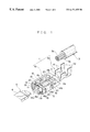
- FIG. 1 is a perspective view of a female terminal according to a first embodiment of this invention, with a male terminal and a cable partly shown;
- FIG. 2 is an enlarged perspective view of a resilient contact member as in FIG. 1;
- FIG. 3 is a view similar to FIG. 2, showing a variant of the resilient contact member
- FIG. 4 is a perspective view of a female terminal according to a second embodiment of this invention, with the male terminal partly shown;
- FIG. 5 is an enlarged perspective view of a resilient contact member as in FIG. 4;
- FIG. 6 is a perspective view of a conventional female terminal
- FIG. 7 is a longitudinal sectional view of the female terminal of FIG. 6;
- FIG. 8 is an enlarged perspective view of a resilient contact member as in FIG. 6, with its wall thickness reduced;
- FIG. 9 is a view similar to FIG. 8, showing the resilient contact member with its wall width reduced.
- FIGS. 1 to 3 show a female terminal according to a first embodiment of this invention.
- a female terminal 1 is formed of a base plate 2 and includes a box-like electrical contact section 10 formed at a front half of the base plate 2 and a cable connection section 40 at which a cable 3 is solderlessly attached, which is formed at a rear half of the base plate 2 .
- the electrical contact section 10 has a bottom wall 11 , side walls 12 , 12 upstanding at opposite sides of the bottom wall 11 , a ceiling wall 13 bridging the side walls 12 , 12 at upper ends thereof, and a resilient contact member 15 received inside the electrical contact section 10 .
- the resilient contact member 15 becomes gradually narrower and then wider from its front end 15 a toward its central contact portion 15 c , and from its contact portion 15 c toward its rear end 15 b , the resilient force changes smoothly in the longitudinal direction of the contact member 15 as compared with the cutouts 20 of rectangular shape, resulting in the male terminal 5 more stably held on the contact portion 15 c of the contact member 15 .
- the electrical contact section 10 has stopper walls 18 at its opposite side walls 12 , 12 , which serve to prevent lateral sliding of the electrical contact section 10 after it is inserted into a terminal receiving cavity (not shown) 11 such that its longitudinally central portion is located at a position elevated from the bottom wall 11 to provide a contact portion 15 c for a mating male terminal 5 .
- the resilient contact member 15 has a later-described low force insertion enabling means at its front half 16 a and rear half 16 b . When inserted through a terminal insertion opening 19 at the front end of the electrical contact section 10 , the tab-like contact portion 6 of the male terminal 5 electrically connects with the contact portion 15 c of the resilient contact member 15 .
- the low force insertion enabling means consists of a pair of cutouts 20 formed in the front half 16 a , at laterally opposite sides thereof, of the resilient contact member 15 between the contact portion 15 c and the front end 15 a and in the rear half 16 b , at laterally opposite sides thereof, between the contact portion 15 c and the rear end 15 b .
- Each cutout 20 may be of curved shape (FIG. 2) or rectangular shape (FIG. 3 ). Although the cutouts of curved shape and rectangular shape are provided in a directly opposed arrangement in the present embodiment, it is also possible to provide them in a slightly longitudinally shifted manner relative to each other. Further, cutouts 20 may be provided at either one of the front and rear halves 16 a , 16 b.
- FIGS. 4 and 5 show a female electrical terminal according to a second embodiment of this invention.
- the female terminal 1 has a resilient contact member 15 ′ whose wall thickness is reduced at its front half 16 a ′ and rear half 16 b ′ to provide thin wall portions 23 . It is also possible to provide the thin wall portion 23 at either one of the front and rear halves 16 a ′ and 16 b ′. Further, the degrees to which the wall thickness is reduced may differ from one to the other of the front and rear halves 16 a ′ and 16 b′.
- the resilient contact member 15 , 15 ′ is shown to be arranged on the bottom wall 11 , it is also possible to arrange same on the ceiling wall 13 . Further, because the low force insertion enabling means as described are only one means for attaining a reduction in the insertion force of the male terminal 5 while fulfilling the condition of easy changeability in design, this invention is not limited to the examples as described above.
Landscapes
- Coupling Device And Connection With Printed Circuit (AREA)
- Connector Housings Or Holding Contact Members (AREA)
Applications Claiming Priority (2)
| Application Number | Priority Date | Filing Date | Title |
|---|---|---|---|
| JP10457198A JP3529026B2 (ja) | 1998-04-15 | 1998-04-15 | 雌端子 |
| JP10-104571 | 1998-04-15 |
Publications (1)
| Publication Number | Publication Date |
|---|---|
| US6171155B1 true US6171155B1 (en) | 2001-01-09 |
Family
ID=14384139
Family Applications (1)
| Application Number | Title | Priority Date | Filing Date |
|---|---|---|---|
| US09/290,423 Expired - Lifetime US6171155B1 (en) | 1998-04-15 | 1999-04-13 | Female electrical terminal with a low insertion force resilient contact member |
Country Status (3)
| Country | Link |
|---|---|
| US (1) | US6171155B1 (de) |
| JP (1) | JP3529026B2 (de) |
| DE (1) | DE19916865C2 (de) |
Cited By (23)
| Publication number | Priority date | Publication date | Assignee | Title |
|---|---|---|---|---|
| US6464548B2 (en) * | 2000-08-28 | 2002-10-15 | Sumitomo Wiring Systems, Ltd. | Female terminal fitting |
| US20060264124A1 (en) * | 2005-05-19 | 2006-11-23 | Deutsch Engineered Connecting Devices | Sleeveless stamped and formed socket contact |
| US7294027B1 (en) | 2006-10-03 | 2007-11-13 | Fci Americas Technology, Inc. | Electrical terminal with layered springs |
| US20090029605A1 (en) * | 2005-12-06 | 2009-01-29 | Toyota Jidosha Kabushiki Kaisha | Female Connector Terminal and Female Connector |
| US20120094550A1 (en) * | 2010-10-19 | 2012-04-19 | Sumitomo Wiring Systems, Ltd. | Terminal fitting |
| US20120100731A1 (en) * | 2009-05-20 | 2012-04-26 | Masayuki Umemoto | Connection terminal, terminal connection structure, and terminal box |
| CN102610458A (zh) * | 2012-03-20 | 2012-07-25 | 吉门保险丝制造(厦门)有限公司 | 一种插接式保险丝组件的插接端子 |
| US20120289101A1 (en) * | 2009-11-11 | 2012-11-15 | Chul-Sub Lee | Connector Terminal |
| CN103620874A (zh) * | 2011-06-21 | 2014-03-05 | 矢崎总业株式会社 | 阴端子 |
| US20140287635A1 (en) * | 2013-03-21 | 2014-09-25 | Sumitomo Wiring Systems, Ltd. | Terminal fitting |
| EP2852004A1 (de) * | 2013-09-20 | 2015-03-25 | Sumitomo Wiring Systems, Ltd. | Anschlussstück |
| US8998657B1 (en) | 2011-01-14 | 2015-04-07 | Reliance Controls Corporation | High current female electrical contact assembly |
| US9054447B1 (en) | 2013-11-14 | 2015-06-09 | Reliance Controls Corporation | Electrical connector using air heated by an electrical arc during disengagement of contacts to extinguish the electrical arc |
| FR3017251A1 (fr) * | 2014-02-06 | 2015-08-07 | Dai Ichi Seiko Co Ltd | Borne de connecteur |
| US9105995B2 (en) | 2013-03-21 | 2015-08-11 | Sumitomo Wiring Systems, Ltd. | Terminal fitting |
| US9419356B2 (en) | 2013-03-14 | 2016-08-16 | Fci Americas Technology Llc | Electrical power contact with two adjacent contact blades abutting each other |
| CN106025581A (zh) * | 2016-06-22 | 2016-10-12 | 深圳市信维通信股份有限公司 | 一种弹片连接器 |
| CN107086396A (zh) * | 2016-02-16 | 2017-08-22 | 第精工株式会社 | 母端子和母端子的制造方法 |
| US10141669B2 (en) * | 2016-08-01 | 2018-11-27 | Te Connectivity Corporation | Plug connector having a tab terminal for a power connector system |
| US10153575B2 (en) * | 2017-03-01 | 2018-12-11 | WAGO Verwaltungsgesellschaft mgH | Conductor connection contact element |
| USD844283S1 (en) * | 2016-08-04 | 2019-04-02 | Brian K. Reis | Edible stick |
| US11217910B2 (en) * | 2019-09-26 | 2022-01-04 | Bjb Gmbh & Co. Kg | Terminal clamp with insertion funnel |
| US20220115802A1 (en) * | 2020-10-09 | 2022-04-14 | I-Pex Inc. | Terminal |
Families Citing this family (8)
| Publication number | Priority date | Publication date | Assignee | Title |
|---|---|---|---|---|
| JP3767506B2 (ja) * | 2002-04-03 | 2006-04-19 | 住友電装株式会社 | 雌側端子金具 |
| JP2005353524A (ja) | 2004-06-14 | 2005-12-22 | Yazaki Corp | 接続端子 |
| JP5388565B2 (ja) * | 2008-12-25 | 2014-01-15 | 矢崎総業株式会社 | メス端子の構造 |
| JP5586192B2 (ja) * | 2009-09-03 | 2014-09-10 | 矢崎総業株式会社 | コネクタ用ターミナル |
| JP5252231B2 (ja) * | 2009-12-02 | 2013-07-31 | 住友電装株式会社 | 雌端子 |
| DE102012023427A1 (de) * | 2012-11-29 | 2014-06-05 | Kostal Kontakt Systeme Gmbh | Steckhülse |
| JP2014165084A (ja) * | 2013-02-27 | 2014-09-08 | D D K Ltd | レセプタクルコネクタ |
| JP6607141B2 (ja) * | 2016-05-12 | 2019-11-20 | 住友電装株式会社 | 端子 |
Citations (6)
| Publication number | Priority date | Publication date | Assignee | Title |
|---|---|---|---|---|
| US4540233A (en) * | 1983-10-01 | 1985-09-10 | Tokai Electric Wire Company Limited | Female electrical terminal having improved contactor block structure |
| US4717356A (en) * | 1986-04-10 | 1988-01-05 | United Technologies Automotive, Inc. | Electrical receptacle terminal |
| US4880401A (en) * | 1987-10-13 | 1989-11-14 | Omron Tateisi Electronics Company | Electric female connector piece |
| US5226842A (en) * | 1991-01-11 | 1993-07-13 | Yazaki Corporation | Female terminal |
| US5271741A (en) * | 1990-02-21 | 1993-12-21 | Yazaki Corporation | Female socket contact |
| US5443592A (en) * | 1993-10-26 | 1995-08-22 | Connecteurs Cinch | Female electrical contact member |
Family Cites Families (3)
| Publication number | Priority date | Publication date | Assignee | Title |
|---|---|---|---|---|
| US4342498A (en) * | 1979-03-26 | 1982-08-03 | Akzona Incorporated | Electrical socket |
| JPH0633659Y2 (ja) * | 1990-02-21 | 1994-08-31 | 矢崎総業株式会社 | 雌型端子金具 |
| JP2865247B2 (ja) * | 1994-06-17 | 1999-03-08 | 矢崎総業株式会社 | 雌型電気接続子における弾性接触片の係止構造 |
-
1998
- 1998-04-15 JP JP10457198A patent/JP3529026B2/ja not_active Expired - Fee Related
-
1999
- 1999-04-13 US US09/290,423 patent/US6171155B1/en not_active Expired - Lifetime
- 1999-04-14 DE DE19916865A patent/DE19916865C2/de not_active Expired - Fee Related
Patent Citations (6)
| Publication number | Priority date | Publication date | Assignee | Title |
|---|---|---|---|---|
| US4540233A (en) * | 1983-10-01 | 1985-09-10 | Tokai Electric Wire Company Limited | Female electrical terminal having improved contactor block structure |
| US4717356A (en) * | 1986-04-10 | 1988-01-05 | United Technologies Automotive, Inc. | Electrical receptacle terminal |
| US4880401A (en) * | 1987-10-13 | 1989-11-14 | Omron Tateisi Electronics Company | Electric female connector piece |
| US5271741A (en) * | 1990-02-21 | 1993-12-21 | Yazaki Corporation | Female socket contact |
| US5226842A (en) * | 1991-01-11 | 1993-07-13 | Yazaki Corporation | Female terminal |
| US5443592A (en) * | 1993-10-26 | 1995-08-22 | Connecteurs Cinch | Female electrical contact member |
Cited By (36)
| Publication number | Priority date | Publication date | Assignee | Title |
|---|---|---|---|---|
| US6464548B2 (en) * | 2000-08-28 | 2002-10-15 | Sumitomo Wiring Systems, Ltd. | Female terminal fitting |
| US20060264124A1 (en) * | 2005-05-19 | 2006-11-23 | Deutsch Engineered Connecting Devices | Sleeveless stamped and formed socket contact |
| US7249983B2 (en) * | 2005-05-19 | 2007-07-31 | Deutsch Engineered Connecting Devices | Sleeveless stamped and formed socket contact |
| US20090029605A1 (en) * | 2005-12-06 | 2009-01-29 | Toyota Jidosha Kabushiki Kaisha | Female Connector Terminal and Female Connector |
| US7775840B2 (en) * | 2005-12-06 | 2010-08-17 | Toyota Jidosha Kabushiki Kaisha | Female connector terminal with internal plate spring |
| US7294027B1 (en) | 2006-10-03 | 2007-11-13 | Fci Americas Technology, Inc. | Electrical terminal with layered springs |
| US8647160B2 (en) * | 2009-05-20 | 2014-02-11 | Yukita Electric Wire Co., Ltd. | Connection terminal, terminal connection structure, and terminal box |
| US20120100731A1 (en) * | 2009-05-20 | 2012-04-26 | Masayuki Umemoto | Connection terminal, terminal connection structure, and terminal box |
| US8827754B2 (en) * | 2009-11-11 | 2014-09-09 | Tyco Electronics Amp Korea, Ltd. | Connector terminal |
| US20120289101A1 (en) * | 2009-11-11 | 2012-11-15 | Chul-Sub Lee | Connector Terminal |
| US8523619B2 (en) * | 2010-10-19 | 2013-09-03 | Sumitomo Wiring Systems, Ltd. | Terminal fitting |
| US20120094550A1 (en) * | 2010-10-19 | 2012-04-19 | Sumitomo Wiring Systems, Ltd. | Terminal fitting |
| US8998657B1 (en) | 2011-01-14 | 2015-04-07 | Reliance Controls Corporation | High current female electrical contact assembly |
| CN103620874A (zh) * | 2011-06-21 | 2014-03-05 | 矢崎总业株式会社 | 阴端子 |
| CN102610458A (zh) * | 2012-03-20 | 2012-07-25 | 吉门保险丝制造(厦门)有限公司 | 一种插接式保险丝组件的插接端子 |
| CN102610458B (zh) * | 2012-03-20 | 2014-09-17 | 吉门保险丝制造(厦门)有限公司 | 一种插接式保险丝组件的插接端子 |
| US9419356B2 (en) | 2013-03-14 | 2016-08-16 | Fci Americas Technology Llc | Electrical power contact with two adjacent contact blades abutting each other |
| US9236675B2 (en) * | 2013-03-21 | 2016-01-12 | Sumitomo Wiring Systems, Ltd. | Terminal fitting |
| US20140287635A1 (en) * | 2013-03-21 | 2014-09-25 | Sumitomo Wiring Systems, Ltd. | Terminal fitting |
| US9105995B2 (en) | 2013-03-21 | 2015-08-11 | Sumitomo Wiring Systems, Ltd. | Terminal fitting |
| EP2852004A1 (de) * | 2013-09-20 | 2015-03-25 | Sumitomo Wiring Systems, Ltd. | Anschlussstück |
| US9184513B2 (en) | 2013-09-20 | 2015-11-10 | Sumitomo Wiring Systems, Ltd. | Terminal fitting |
| US9054447B1 (en) | 2013-11-14 | 2015-06-09 | Reliance Controls Corporation | Electrical connector using air heated by an electrical arc during disengagement of contacts to extinguish the electrical arc |
| FR3017251A1 (fr) * | 2014-02-06 | 2015-08-07 | Dai Ichi Seiko Co Ltd | Borne de connecteur |
| CN107086396A (zh) * | 2016-02-16 | 2017-08-22 | 第精工株式会社 | 母端子和母端子的制造方法 |
| EP3208888A1 (de) * | 2016-02-16 | 2017-08-23 | Dai-Ichi Seiko Co., Ltd. | Buchsenanschlussstück und verfahren zur herstellung des buchsenanschlussstücks |
| EP3367506A1 (de) * | 2016-02-16 | 2018-08-29 | Dai-Ichi Seiko Co., Ltd. | Buchsenanschlussstück |
| US10069232B2 (en) | 2016-02-16 | 2018-09-04 | Dai-Ichi Seiko Co., Ltd. | Female terminal and female terminal production method |
| CN107086396B (zh) * | 2016-02-16 | 2020-11-27 | 第一精工株式会社 | 母端子和母端子的制造方法 |
| CN106025581B (zh) * | 2016-06-22 | 2019-02-12 | 深圳市信维通信股份有限公司 | 一种弹片连接器 |
| CN106025581A (zh) * | 2016-06-22 | 2016-10-12 | 深圳市信维通信股份有限公司 | 一种弹片连接器 |
| US10141669B2 (en) * | 2016-08-01 | 2018-11-27 | Te Connectivity Corporation | Plug connector having a tab terminal for a power connector system |
| USD844283S1 (en) * | 2016-08-04 | 2019-04-02 | Brian K. Reis | Edible stick |
| US10153575B2 (en) * | 2017-03-01 | 2018-12-11 | WAGO Verwaltungsgesellschaft mgH | Conductor connection contact element |
| US11217910B2 (en) * | 2019-09-26 | 2022-01-04 | Bjb Gmbh & Co. Kg | Terminal clamp with insertion funnel |
| US20220115802A1 (en) * | 2020-10-09 | 2022-04-14 | I-Pex Inc. | Terminal |
Also Published As
| Publication number | Publication date |
|---|---|
| JP3529026B2 (ja) | 2004-05-24 |
| JPH11297392A (ja) | 1999-10-29 |
| DE19916865A1 (de) | 1999-10-28 |
| DE19916865C2 (de) | 2001-08-09 |
Similar Documents
| Publication | Publication Date | Title |
|---|---|---|
| US6171155B1 (en) | Female electrical terminal with a low insertion force resilient contact member | |
| US6062918A (en) | Electrical receptacle contact assembly | |
| EP0932917B1 (de) | Elektrischer verbinder mit einem gehäuse und einem elektrischen kontaktelement | |
| US4633048A (en) | Jack with a switch | |
| US5380220A (en) | Connector | |
| US4969841A (en) | Double locking structure for terminal in electrical connectors | |
| US7883362B2 (en) | Joint connector, joint terminal and a wiring harness with a joint connector | |
| US6315591B2 (en) | Electrical connector having an improved female contact | |
| US6325680B1 (en) | Female contact for an electrical connector | |
| US5938485A (en) | Electrical terminal | |
| US7563135B2 (en) | Connector | |
| US20050118891A1 (en) | Female terminal for heavy current and female terminal for heavy current with shell | |
| US10770821B2 (en) | Electrical connector and connector assembly having the same | |
| US5899775A (en) | Contact with retention lance and housing therefor | |
| US6669507B2 (en) | Connector | |
| US3901575A (en) | Plug for patch systems | |
| US20020146941A1 (en) | Insulator coring and contact configuration to prevent pin stubbing in the throat of tuning fork socket connector contacts | |
| US5160279A (en) | Double lock connector | |
| CN109980404B (zh) | 具有下压肋的插座连接器壳体 | |
| US6589080B2 (en) | Terminal fitting and a connector | |
| US5975930A (en) | Slide fit connector | |
| US5944554A (en) | Electrical connector for flat flexible circuits | |
| US6165027A (en) | Electrical connector | |
| US6416366B2 (en) | Terminal metal fitting | |
| US6328606B1 (en) | High density electrical connector system |
Legal Events
| Date | Code | Title | Description |
|---|---|---|---|
| AS | Assignment |
Owner name: YAZAKI CORPORATION, JAPAN Free format text: ASSIGNMENT OF ASSIGNORS INTEREST;ASSIGNORS:MIWA, TAKEYA;TANAKA, SHIGERU;REEL/FRAME:009902/0853 Effective date: 19990406 |
|
| STCF | Information on status: patent grant |
Free format text: PATENTED CASE |
|
| FEPP | Fee payment procedure |
Free format text: PAYER NUMBER DE-ASSIGNED (ORIGINAL EVENT CODE: RMPN); ENTITY STATUS OF PATENT OWNER: LARGE ENTITY Free format text: PAYOR NUMBER ASSIGNED (ORIGINAL EVENT CODE: ASPN); ENTITY STATUS OF PATENT OWNER: LARGE ENTITY |
|
| FPAY | Fee payment |
Year of fee payment: 4 |
|
| FPAY | Fee payment |
Year of fee payment: 8 |
|
| FPAY | Fee payment |
Year of fee payment: 12 |