US6151876A - Method and apparatus for shaping a part of a plant - Google Patents
Method and apparatus for shaping a part of a plant Download PDFInfo
- Publication number
- US6151876A US6151876A US09/240,631 US24063199A US6151876A US 6151876 A US6151876 A US 6151876A US 24063199 A US24063199 A US 24063199A US 6151876 A US6151876 A US 6151876A
- Authority
- US
- United States
- Prior art keywords
- plant
- cutting
- respect
- rotational axis
- pot
- Prior art date
- Legal status (The legal status is an assumption and is not a legal conclusion. Google has not performed a legal analysis and makes no representation as to the accuracy of the status listed.)
- Expired - Fee Related
Links
Images

Classifications
-
- A—HUMAN NECESSITIES
- A01—AGRICULTURE; FORESTRY; ANIMAL HUSBANDRY; HUNTING; TRAPPING; FISHING
- A01G—HORTICULTURE; CULTIVATION OF VEGETABLES, FLOWERS, RICE, FRUIT, VINES, HOPS OR SEAWEED; FORESTRY; WATERING
- A01G3/00—Cutting implements specially adapted for horticultural purposes; Delimbing standing trees
- A01G3/04—Apparatus for trimming hedges, e.g. hedge shears
- A01G3/0435—Machines specially adapted for shaping plants, e.g. topiaries
Definitions
- the present invention relates to a method according to the preamble of claim 1.
- the cutting be carried out, as far as is possible, ⁇ upstream ⁇ , seen in the direction of rotation of the plant. Surprisingly, this has been found to significantly limit or even totally remove the problem of ⁇ double cutting ⁇ .
- This movement must be distinguished from the different possibilities of shaping the plant in question. It is possible, with one pair of cutters, when carrying out the mutual rotational movement of plant and cutters, to carry out a movement to achieve a particular form. This movement can be performed in any desired curve. In a simple embodiment, this is a circular path, so that a circular shape is given to the plant. In a further embodiment, a more complex path is used, controlled by a jig if necessary.
- Another approach is the use of several pairs of shears, stationary during use, which together determine the shape of the plant.
- the invention also relates to an apparatus for the shaping of a part of a potted plant according to claim 7. It is here also possible, in the case of a pot plant, to turn that pot plant with respect to the cutting means, which are stationary in this direction of rotation. For plants in the soil, it is possible to use a supporting frame which is moved around/over the plant, where the cutting means can make a rotation, with respect to the supporting frame, which corresponds to the desired central axis of the shape that is to be given to the plant.
- the method described above can be achieved using two embodiments.
- the first embodiment consists of a frame with a moveable, and more particularly, a hinged arm attachment, on which the preferably electrically operated cutting means are attached.
- the cutting means are fixed to an (auxiliary) frame and several cutting means are positioned around the circumference of the desired shape, which together, due to the rotation of the plant, realize the required shape.
- Vacuum extraction means should preferably be present to remove the clippings on the spot, so that contamination of the apparatus is avoided wherever possible.
- a clamping means can likewise be fitted for the plant pot, and rotation of the pot can occur both by the turning of the plateau on which this is mounted and by the separate rotating pressing means which grip the sides of the pot. Finally, supply and removal means for the pot can be present.
- the apparatus described above can be constructed to be moveable. enabling it to be moved to the plant in question.
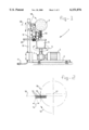
- FIG. 1 shows a side view of a first embodiment according to the invention
- FIG. 2 shows a schematic top down view of the positioning of the shears with respect to the plant
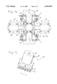
- FIG. 3 shows a side view of a further embodiment according to the invention.
- FIG. 4 shows a top down view of the lower part of the embodiment shown in FIG. 3;
- FIG. 5 shows the shears 30 shown in FIG. 3, in detail.
- FIG. 1 shows the complete apparatus according to the invention.
- This consists of a frame 2 with a motor 3 fitted to it.
- the drive shaft of the motor is connected to a right angled transmission 4, which in turn is connected to a rotating table 5.
- a pot 6 containing a plant 7 can be placed on the table 5.
- a post 8 is joined to frame 2.
- a hinged arm 9 is mounted on this post 8. This arm 9 can hinge in the direction of arrow 18.
- a pair of shears 10 are attached to the end of the arm 9. These are provided with cutting blades which are not elaborated on further here.
- the shears 10 work electrically and the supply cable is indicated by 11.
- FIG. 2 the positioning of the various blades 13 of the shears 13 with respect to the plant is shown, in a top down view. Between the blades of the shears is a cutting gap 14. The intersections of the cutting gap and the plant is indicated by 15. A line 16 is drawn between the two intersections 15. In the rotational direction 12 of the plant shown, line 16 lies in front of the center 17 of the circle.
- intersection where the plant is gripped in the cutting gap 14, lies on a central axis 19. wherein the contact point of the central axis 19 with a circle with center 17 lies at a point above that intersection.
- clipping takes place, as far as is possible, at a point above the intersection point, seen in the direction of rotation 12. This principle holds for all embodiments of the invention and is important in order to avoid double clipping.
- the shaping of a plant takes place by letting arm 9 make circular movements along the plant, as indicated by arrow 18, while the plant is being rotated on table 5. During this movement, the shears 10 are activated so that the spherical form shown in FIG. 1 is achieved. The process is then controlled by gripping handle 20 and rotating around the central axis 39. In place of the circular trajectory of arm 9, any other path can be followed by the blades of the shears. To this end, a jig could be used to determine the trajectory of the cutting means.
- FIGS. 3 and 4 a further embodiment of the invention is shown.
- the complete apparatus is indicated by 21 and consists of a frame 22.
- frame 22 can be closed off from the surrounding area by doors and such like, for safety reasons.
- the frame has wheels 43 to enable the apparatus to be moved.
- motors 23 are present, operating four pressure-rollers 24. These motors 23 are fixed on the relevant auxiliary frames 28.
- ⁇ stationary ⁇ should be understood as being stationary during use.
- Various possible adjustment mechanisms are present to adjust the apparatus to the particular plant and the clipped shape required.
- a plant pot, indicated by 26, is gripped by the pressure-rollers 24 and is in this way rotated.
- the pot is supported by the conveyor belt 25, which also supplies and removes the pot and plant 27.
- the auxiliary frames 28 can be moved backwards and forwards with the help of pneumatic piston cylinder structures 29. These pneumatic piston cylinder structures 29 grip onto a belt 37 which rotates rods 38, at the far ends of the apparatus, via a suitable gear wheel, causing belt 36 to move backwards and forwards.
- the auxiliary frames 28 move along the upper guidance rails 34 and the lower guidance rails 35 and, with the help of belts 36 and 37, are optimally positioned.
- the pressing force of the pressure-rollers 24 against the pot 26 can easily be controlled using the pneumatic piston cylinder structures 29. The pressing force depends on the dimensions of the pot and its stiffness.
- means for holding down 32, which grip the top edge of the pot 26, are mounted on the auxiliary frame.
- Stationary shears 30 are also mounted on the auxiliary frames. These consist of an electric motor 40 which is supplied with electricity by some means or other, as can be seen in FIG. 5. A first reciprocal blade 41 is present which moves in co-operation with a second reciprocal blade. Moreover, the cutting means are applied at various positions around the circumference and at different heights. Of importance is that the positioning always takes place as described using FIG. 2. In addition, vacuum extraction means 31 are present near the shears 30. These are only shown once. These can consist of a funnel with a pipe for the vacuuming of the plant clippings.
- the apparatus described above functions as follows.
- the auxiliary frames 28 with the pressure-rollers and the shears 30 are moved away from each other, allowing free passage of the pots through the apparatus. These are placed on the conveyor belt 25 and moved to the center of the apparatus. The pot and or the plant is then detected and, regardless of whether the conveyor belt 25 stops or not, the auxiliary frames 28 are moved towards each other. The pressure-rollers 24 thus press the pot into a defined position.
- the holding down means 32 then also move over the edge of the pot 26 so that it cannot tip over.
- the use of this sort of holding down means 32 depends on the weight of the pot and the circumference of the plant to be clipped.
- the pot is turned by the pressure-rollers 24.
- each of the pressure-rollers in the present embodiment is individually driven, one or more rollers can be embodied without such a drive.
- the shears 30 are powered simultaneously and the clipping of the plant 27 takes place.
- the auxiliary frames are once more moved away from each other and the pot in question can be removed via the conveyor belt 25.
- the handling time of, for example a buxus can be reduced significantly. Where, for example, 3 minutes were needed for manual clipping, this can be limited to 10 seconds per plant while, by increasing the supply speed and the speed of rotation, the yield can be improved further.
Applications Claiming Priority (2)
| Application Number | Priority Date | Filing Date | Title |
|---|---|---|---|
| NL1008163A NL1008163C2 (nl) | 1998-01-30 | 1998-01-30 | Werkwijze en inrichting voor het modelleren van een deel van een gewas. |
| NL1008163 | 1998-01-30 |
Publications (1)
| Publication Number | Publication Date |
|---|---|
| US6151876A true US6151876A (en) | 2000-11-28 |
Family
ID=19766437
Family Applications (1)
| Application Number | Title | Priority Date | Filing Date |
|---|---|---|---|
| US09/240,631 Expired - Fee Related US6151876A (en) | 1998-01-30 | 1999-02-01 | Method and apparatus for shaping a part of a plant |
Country Status (5)
| Country | Link |
|---|---|
| US (1) | US6151876A (de) |
| EP (1) | EP0933019B1 (de) |
| CA (1) | CA2260544A1 (de) |
| DE (1) | DE69906605T2 (de) |
| NL (1) | NL1008163C2 (de) |
Cited By (13)
| Publication number | Priority date | Publication date | Assignee | Title |
|---|---|---|---|---|
| US6609356B2 (en) * | 2001-04-30 | 2003-08-26 | Monrovia Nursery Company | Mower with vertically movable platform |
| US20040200199A1 (en) * | 2001-05-28 | 2004-10-14 | Andre Colens | Automatic hedge-trimming system |
| US20080078088A1 (en) * | 2006-09-28 | 2008-04-03 | Vastgoedmaatschappij Gebr. Ezendam B.V. | Device and method for cultivating a crop, and also assembly of a device of this type and a crop |
| US7603781B1 (en) | 2005-02-14 | 2009-10-20 | Szoke Jr Anthony A | Foliage trimmer with adjustable curvature of the flexible cutting blade assembly |
| US7707727B1 (en) * | 2005-02-14 | 2010-05-04 | Szoke Anthony A | Foliage trimmers with adjustable curvature of cutting sections |
| US8025141B1 (en) | 2008-12-23 | 2011-09-27 | Bouldin Corporation | Contour trimmer for potted plants |
| US20150305250A1 (en) * | 2014-03-27 | 2015-10-29 | Des Moines Area Community College | Methods and Systems for Increasing Soybean Yields |
| US10369693B1 (en) | 2016-11-10 | 2019-08-06 | X Development Llc | Cable suspended robotic system |
| US10433498B1 (en) | 2016-01-28 | 2019-10-08 | Jason Finch | System for improving plant yield |
| US10645882B1 (en) * | 2018-10-29 | 2020-05-12 | Advanced Intelligent Systems Inc. | Method and apparatus for performing pruning operations using an autonomous vehicle |
| US10966374B2 (en) * | 2018-10-29 | 2021-04-06 | Advanced Intelligent Systems Inc. | Method and apparatus for performing pruning operations using an autonomous vehicle |
| US20210276212A1 (en) * | 2020-03-06 | 2021-09-09 | Flexible Steel Lacing Company | Cutting apparatus and method for cutting belts |
| US11375672B2 (en) * | 2019-08-20 | 2022-07-05 | San Tomo, Inc. | System for hedge pruning and method for making and using the same |
Families Citing this family (8)
| Publication number | Priority date | Publication date | Assignee | Title |
|---|---|---|---|---|
| NL1036136C2 (nl) * | 2008-10-31 | 2009-08-19 | Richard Gerardus Maria Van Der Wal | Een inrichting voor het volautomatisch snijden van bomen en planten in exacte bolvorm. |
| IT1393635B1 (it) * | 2009-04-29 | 2012-05-08 | Borselli | Macchina spuntatrice per piante in vaso e in terra. |
| ITFI20090086A1 (it) * | 2009-04-29 | 2010-10-30 | Borselli Ademaro | Macchina spuntatrice per piante in vaso e in terra. |
| IT1401030B1 (it) * | 2010-07-23 | 2013-07-12 | Mec Di Braganti Emilio & Gonfia Pier Paolo S N C Off | Macchina cimatrice-potatrice, particolarmente per la potatura di frutteti, noccioleti, agrumeti, uliveti e similari |
| CN104025919B (zh) * | 2014-06-19 | 2015-09-30 | 国网四川省电力公司成都市新都供电分公司 | 盆栽修剪工具 |
| CN104025918B (zh) * | 2014-06-19 | 2015-09-30 | 国网四川省电力公司成都市新都供电分公司 | 一种盆栽修剪工具 |
| CN106561309A (zh) * | 2016-11-07 | 2017-04-19 | 江苏建筑职业技术学院 | 灌木顶面四叶玫瑰形槽可调式修剪器 |
| CN113785709A (zh) * | 2021-09-14 | 2021-12-14 | 张家港市星星工具制造有限公司 | 一种适用不同大小盆景的园艺修剪用塑型装置 |
Citations (14)
| Publication number | Priority date | Publication date | Assignee | Title |
|---|---|---|---|---|
| DE170948C (de) * | ||||
| US1627258A (en) * | 1926-10-16 | 1927-05-03 | John J Sullivan | Hedge trimmer |
| US3496709A (en) * | 1967-04-10 | 1970-02-24 | Fred W Swan | Automatic tree trimming mechanism |
| US3635004A (en) * | 1970-03-02 | 1972-01-18 | Research Corp | Orchard machine |
| DE2155357A1 (de) * | 1971-11-08 | 1973-05-17 | Guenter Pfaff Fa | Verfahren und vorrichtung zum beschneiden von blumen in toepfen |
| US3913304A (en) * | 1974-05-17 | 1975-10-21 | Paul Jodoin | Tree trimmer |
| US4382332A (en) * | 1981-08-03 | 1983-05-10 | Bordier's Nursery California, Inc. | Pruning machine |
| US4383401A (en) * | 1981-10-30 | 1983-05-17 | Christmas Trees, Ltd. | Twin mounted double sided reciprocating shaping mechanism |
| US4543775A (en) * | 1979-04-23 | 1985-10-01 | Up-Right, Inc. | Method and apparatus for pruning cordon-trained grape vines |
| US4777787A (en) * | 1986-08-07 | 1988-10-18 | Anjo Tree Shapers, Inc. | Tree shaping apparatus |
| US4970791A (en) * | 1989-09-05 | 1990-11-20 | Vergara Florentino S | Vegetation trimming apparatus for rounded configurations |
| US5020309A (en) * | 1989-11-08 | 1991-06-04 | Textron, Inc. | Leaf shredder attachment for a mower bagging system |
| DE4110582A1 (de) * | 1991-03-30 | 1992-10-01 | Mayer App & Masch | Verfahren und vorrichtung zum zuschneiden von pflanzen in toepfen, insbesondere von azaleen |
| NL9301671A (nl) * | 1992-09-28 | 1994-04-18 | Gregoire B V B A Fa | Inrichting voor het snoeien van plantjes, hoofdzakelijk van in potten gekweekte plantjes. |
Family Cites Families (1)
| Publication number | Priority date | Publication date | Assignee | Title |
|---|---|---|---|---|
| DE4409126C1 (de) * | 1994-03-17 | 1995-06-01 | Eduard Aschoff | Vorrichtung zum Schneiden von Buchsbaum |
-
1998
- 1998-01-30 NL NL1008163A patent/NL1008163C2/nl not_active IP Right Cessation
-
1999
- 1999-02-01 CA CA002260544A patent/CA2260544A1/en not_active Abandoned
- 1999-02-01 US US09/240,631 patent/US6151876A/en not_active Expired - Fee Related
- 1999-02-01 EP EP99200284A patent/EP0933019B1/de not_active Expired - Lifetime
- 1999-02-01 DE DE69906605T patent/DE69906605T2/de not_active Expired - Lifetime
Patent Citations (14)
| Publication number | Priority date | Publication date | Assignee | Title |
|---|---|---|---|---|
| DE170948C (de) * | ||||
| US1627258A (en) * | 1926-10-16 | 1927-05-03 | John J Sullivan | Hedge trimmer |
| US3496709A (en) * | 1967-04-10 | 1970-02-24 | Fred W Swan | Automatic tree trimming mechanism |
| US3635004A (en) * | 1970-03-02 | 1972-01-18 | Research Corp | Orchard machine |
| DE2155357A1 (de) * | 1971-11-08 | 1973-05-17 | Guenter Pfaff Fa | Verfahren und vorrichtung zum beschneiden von blumen in toepfen |
| US3913304A (en) * | 1974-05-17 | 1975-10-21 | Paul Jodoin | Tree trimmer |
| US4543775A (en) * | 1979-04-23 | 1985-10-01 | Up-Right, Inc. | Method and apparatus for pruning cordon-trained grape vines |
| US4382332A (en) * | 1981-08-03 | 1983-05-10 | Bordier's Nursery California, Inc. | Pruning machine |
| US4383401A (en) * | 1981-10-30 | 1983-05-17 | Christmas Trees, Ltd. | Twin mounted double sided reciprocating shaping mechanism |
| US4777787A (en) * | 1986-08-07 | 1988-10-18 | Anjo Tree Shapers, Inc. | Tree shaping apparatus |
| US4970791A (en) * | 1989-09-05 | 1990-11-20 | Vergara Florentino S | Vegetation trimming apparatus for rounded configurations |
| US5020309A (en) * | 1989-11-08 | 1991-06-04 | Textron, Inc. | Leaf shredder attachment for a mower bagging system |
| DE4110582A1 (de) * | 1991-03-30 | 1992-10-01 | Mayer App & Masch | Verfahren und vorrichtung zum zuschneiden von pflanzen in toepfen, insbesondere von azaleen |
| NL9301671A (nl) * | 1992-09-28 | 1994-04-18 | Gregoire B V B A Fa | Inrichting voor het snoeien van plantjes, hoofdzakelijk van in potten gekweekte plantjes. |
Cited By (16)
| Publication number | Priority date | Publication date | Assignee | Title |
|---|---|---|---|---|
| US6609356B2 (en) * | 2001-04-30 | 2003-08-26 | Monrovia Nursery Company | Mower with vertically movable platform |
| US6889489B2 (en) | 2001-04-30 | 2005-05-10 | Monrovia Nursery Company | Mower with vertically movable platform |
| US20040200199A1 (en) * | 2001-05-28 | 2004-10-14 | Andre Colens | Automatic hedge-trimming system |
| US7603781B1 (en) | 2005-02-14 | 2009-10-20 | Szoke Jr Anthony A | Foliage trimmer with adjustable curvature of the flexible cutting blade assembly |
| US7707727B1 (en) * | 2005-02-14 | 2010-05-04 | Szoke Anthony A | Foliage trimmers with adjustable curvature of cutting sections |
| US20080078088A1 (en) * | 2006-09-28 | 2008-04-03 | Vastgoedmaatschappij Gebr. Ezendam B.V. | Device and method for cultivating a crop, and also assembly of a device of this type and a crop |
| US7814738B2 (en) * | 2006-09-28 | 2010-10-19 | Vastgoedmaatschappij Gebr. Ezendam B.V. | Device and method for cultivating a crop, and also assembly of a device of this type and a crop |
| US8025141B1 (en) | 2008-12-23 | 2011-09-27 | Bouldin Corporation | Contour trimmer for potted plants |
| US20150305250A1 (en) * | 2014-03-27 | 2015-10-29 | Des Moines Area Community College | Methods and Systems for Increasing Soybean Yields |
| US10433498B1 (en) | 2016-01-28 | 2019-10-08 | Jason Finch | System for improving plant yield |
| US10369693B1 (en) | 2016-11-10 | 2019-08-06 | X Development Llc | Cable suspended robotic system |
| US10645882B1 (en) * | 2018-10-29 | 2020-05-12 | Advanced Intelligent Systems Inc. | Method and apparatus for performing pruning operations using an autonomous vehicle |
| US10966374B2 (en) * | 2018-10-29 | 2021-04-06 | Advanced Intelligent Systems Inc. | Method and apparatus for performing pruning operations using an autonomous vehicle |
| US11375672B2 (en) * | 2019-08-20 | 2022-07-05 | San Tomo, Inc. | System for hedge pruning and method for making and using the same |
| US20210276212A1 (en) * | 2020-03-06 | 2021-09-09 | Flexible Steel Lacing Company | Cutting apparatus and method for cutting belts |
| US11850765B2 (en) * | 2020-03-06 | 2023-12-26 | Flexible Steel Lacing Company | Cutting apparatus and method for cutting belts |
Also Published As
| Publication number | Publication date |
|---|---|
| EP0933019B1 (de) | 2003-04-09 |
| DE69906605D1 (de) | 2003-05-15 |
| EP0933019A1 (de) | 1999-08-04 |
| DE69906605T2 (de) | 2004-02-12 |
| CA2260544A1 (en) | 1999-07-30 |
| NL1008163C2 (nl) | 1999-08-04 |
Similar Documents
| Publication | Publication Date | Title |
|---|---|---|
| US6151876A (en) | Method and apparatus for shaping a part of a plant | |
| AU611490B2 (en) | Broccoli trimming machine | |
| US6250056B1 (en) | Rotary blade pruning machine | |
| CA2775457A1 (en) | Method and apparatus for trimming buds and flowers | |
| CN112470829B (zh) | 一种自动控制的真菌采收装置 | |
| EP0112365B1 (de) | Maschine zum entfernen von material von baumstämmen | |
| JPH0241201A (ja) | 樹幹を枝打ち及び切断する装置 | |
| EP0168117A1 (de) | Vorrichtung zum Entfernen der Käserinde | |
| EP1399011B1 (de) | Verfahren zur abtrennung von phyllokladien von phyllocacti | |
| WO2010125600A1 (en) | Machine for trimming plants | |
| WO1998030079A1 (en) | Pruning apparatus | |
| CN113001658B (zh) | 芽菜自动加工处理装置 | |
| CN212212035U (zh) | 鲜花切枝铡刀 | |
| CN209599770U (zh) | 汽车塑料零部件的自动翻转剪浇口设备 | |
| CN114027026B (zh) | 一种牡丹深加工过程中用的背负式收割设备 | |
| CN214961271U (zh) | 一种林业修剪装置 | |
| JPH0524264Y2 (de) | ||
| AU736196B2 (en) | Pruning apparatus | |
| JP2548320Y2 (ja) | 生花の下葉取装置 | |
| KR970005245Y1 (ko) | 호박 커팅장치 | |
| SU1047439A1 (ru) | Захватно-срезающее устройство лесозаготовительной машины | |
| JPS5933245Y2 (ja) | 枝打ち機 | |
| CN113841510A (zh) | 剑麻叶收割机 | |
| CA1214977A (en) | Machine for removing material from logs | |
| SU1274676A1 (ru) | Машина дл обрезки концов моркови |
Legal Events
| Date | Code | Title | Description |
|---|---|---|---|
| REMI | Maintenance fee reminder mailed | ||
| LAPS | Lapse for failure to pay maintenance fees | ||
| STCH | Information on status: patent discontinuation |
Free format text: PATENT EXPIRED DUE TO NONPAYMENT OF MAINTENANCE FEES UNDER 37 CFR 1.362 |
|
| FP | Expired due to failure to pay maintenance fee |
Effective date: 20041128 |