US6076547A - Device for operating a mechanism of a rinsing fixture - Google Patents
Device for operating a mechanism of a rinsing fixture Download PDFInfo
- Publication number
- US6076547A US6076547A US09/134,844 US13484498A US6076547A US 6076547 A US6076547 A US 6076547A US 13484498 A US13484498 A US 13484498A US 6076547 A US6076547 A US 6076547A
- Authority
- US
- United States
- Prior art keywords
- float
- force means
- valve
- arrangement
- fluid force
- Prior art date
- Legal status (The legal status is an assumption and is not a legal conclusion. Google has not performed a legal analysis and makes no representation as to the accuracy of the status listed.)
- Expired - Fee Related
Links
Images


Classifications
-
- E—FIXED CONSTRUCTIONS
- E03—WATER SUPPLY; SEWERAGE
- E03F—SEWERS; CESSPOOLS
- E03F9/00—Arrangements or fixed installations methods or devices for cleaning or clearing sewer pipes, e.g. by flushing
-
- E—FIXED CONSTRUCTIONS
- E03—WATER SUPPLY; SEWERAGE
- E03F—SEWERS; CESSPOOLS
- E03F5/00—Sewerage structures
- E03F5/10—Collecting-tanks; Equalising-tanks for regulating the run-off; Laying-up basins
- E03F5/105—Accessories, e.g. flow regulators or cleaning devices
-
- E—FIXED CONSTRUCTIONS
- E03—WATER SUPPLY; SEWERAGE
- E03F—SEWERS; CESSPOOLS
- E03F9/00—Arrangements or fixed installations methods or devices for cleaning or clearing sewer pipes, e.g. by flushing
- E03F9/007—Devices providing a flushing surge
-
- Y—GENERAL TAGGING OF NEW TECHNOLOGICAL DEVELOPMENTS; GENERAL TAGGING OF CROSS-SECTIONAL TECHNOLOGIES SPANNING OVER SEVERAL SECTIONS OF THE IPC; TECHNICAL SUBJECTS COVERED BY FORMER USPC CROSS-REFERENCE ART COLLECTIONS [XRACs] AND DIGESTS
- Y10—TECHNICAL SUBJECTS COVERED BY FORMER USPC
- Y10T—TECHNICAL SUBJECTS COVERED BY FORMER US CLASSIFICATION
- Y10T137/00—Fluid handling
- Y10T137/7287—Liquid level responsive or maintaining systems
- Y10T137/7358—By float controlled valve
- Y10T137/7365—Single float controls plural valves
-
- Y—GENERAL TAGGING OF NEW TECHNOLOGICAL DEVELOPMENTS; GENERAL TAGGING OF CROSS-SECTIONAL TECHNOLOGIES SPANNING OVER SEVERAL SECTIONS OF THE IPC; TECHNICAL SUBJECTS COVERED BY FORMER USPC CROSS-REFERENCE ART COLLECTIONS [XRACs] AND DIGESTS
- Y10—TECHNICAL SUBJECTS COVERED BY FORMER USPC
- Y10T—TECHNICAL SUBJECTS COVERED BY FORMER US CLASSIFICATION
- Y10T137/00—Fluid handling
- Y10T137/7287—Liquid level responsive or maintaining systems
- Y10T137/7358—By float controlled valve
- Y10T137/7368—Servo relay operation of control
- Y10T137/7371—Fluid pressure
-
- Y—GENERAL TAGGING OF NEW TECHNOLOGICAL DEVELOPMENTS; GENERAL TAGGING OF CROSS-SECTIONAL TECHNOLOGIES SPANNING OVER SEVERAL SECTIONS OF THE IPC; TECHNICAL SUBJECTS COVERED BY FORMER USPC CROSS-REFERENCE ART COLLECTIONS [XRACs] AND DIGESTS
- Y10—TECHNICAL SUBJECTS COVERED BY FORMER USPC
- Y10T—TECHNICAL SUBJECTS COVERED BY FORMER US CLASSIFICATION
- Y10T137/00—Fluid handling
- Y10T137/7287—Liquid level responsive or maintaining systems
- Y10T137/7358—By float controlled valve
- Y10T137/7381—Quick acting
- Y10T137/7394—Trip mechanism
- Y10T137/7397—Weight or spring bias
-
- Y—GENERAL TAGGING OF NEW TECHNOLOGICAL DEVELOPMENTS; GENERAL TAGGING OF CROSS-SECTIONAL TECHNOLOGIES SPANNING OVER SEVERAL SECTIONS OF THE IPC; TECHNICAL SUBJECTS COVERED BY FORMER USPC CROSS-REFERENCE ART COLLECTIONS [XRACs] AND DIGESTS
- Y10—TECHNICAL SUBJECTS COVERED BY FORMER USPC
- Y10T—TECHNICAL SUBJECTS COVERED BY FORMER US CLASSIFICATION
- Y10T137/00—Fluid handling
- Y10T137/7287—Liquid level responsive or maintaining systems
- Y10T137/7358—By float controlled valve
- Y10T137/7381—Quick acting
- Y10T137/74—Lost motion mechanism
-
- Y—GENERAL TAGGING OF NEW TECHNOLOGICAL DEVELOPMENTS; GENERAL TAGGING OF CROSS-SECTIONAL TECHNOLOGIES SPANNING OVER SEVERAL SECTIONS OF THE IPC; TECHNICAL SUBJECTS COVERED BY FORMER USPC CROSS-REFERENCE ART COLLECTIONS [XRACs] AND DIGESTS
- Y10—TECHNICAL SUBJECTS COVERED BY FORMER USPC
- Y10T—TECHNICAL SUBJECTS COVERED BY FORMER US CLASSIFICATION
- Y10T137/00—Fluid handling
- Y10T137/7287—Liquid level responsive or maintaining systems
- Y10T137/7358—By float controlled valve
- Y10T137/7404—Plural floats
Definitions
- the invention relates to a device for operating a mechanism of a rinsing fixture. It concerns, in particular, a device for operation of a closing and opening mechanism or of a locking mechanism of a rinsing fixture.
- the device comprises a float and a first hydraulic of pneumatic force means that shows a regulating unit controllable by means of the float as well as a second hydraulic or pneumatic force means that shows a hydraulic or pneumatic regulating unit that is connected with the regulating unit of the first force means, whereby this regulating unit is actively coupled to the mechanism.
- the float is attached, for example, to a rod.
- the regulating unit of the first force means is able to be driven by this float rod.
- a device for operating the closing and opening mechanism of the type named in the introduction is known from DE 37 18 812 A1.
- the mechanism serves to operate a float-controlled cut-off valve of a rinsing chamber for rinsing a storage space for a liquid, whereby the float is effective in the region of the low point of the bottom of the storage space.
- the float rod connected to the float operates the mechanism of the cut-off valve, the float rod being fixedly connected with the regulating unit related to the valve, whereby the regulating unit is operated by the lifting as well as by the sinking of the float.
- EP 0 658 657 A2 is known a device for operating a locking mechanism of a tilt-rinsing fixture for rinsing a length of channel.
- the liquid level of the channel at any given time is determined by an inductive sensor and is passed on by an evaluation unit, which then, when it ascertains a complete emptying of the channel or channel shaft, sends forward a releasing impulse to the locking mechanism that holds fast the tilt-rinsing equipment that is filled with rinsing liquid.
- the task of the present invention is to advance the design of a device according to the type mentioned in the introduction for operating a mechanism of a rinsing fixture, in particular for operation of a closing and opening mechanism or of a locking mechanism of a rinsing fixture, so that a rapid float-controlled activation of the mechanism of a rinsing fixture for instantaneous rinsing is assured and that this is done in a simple manner as well as with little production expense.
- the task is solved in a device of the type named in the introduction in this way, that the float upon rising drives, against a restoring force, the regulating unit of the first force means for operating the mechanism, that the float upon sinking is uncoupled from the regulating unit of the first force means, and that in the connection of the two force means a valve is arranged that is controlled by the float for moving the regulating unit of the first force means or is controlled by another float, in such a manner that the connection is opened by the lifting of the float, that it is closed off by the raised float as well as during the sinking of the float and that it is opened by the sunken float.
- the float is coupled to the regulating unit of the first force only when raised.
- the regulating unit of the first force means moves together with the float and, due to the connection with the regulating unit of the second force means, causes the latter regulating unit to likewise be moved and thus, for example, operate the closing mechanism in the sense of a closing movement or transfer the locking mechanism into its locking position.
- the float Since with the sinking the float is uncoupled from the regulating unit of the first force means, the float itself cannot transfer the closing mechanism into its open position or the locking mechanism into its released position. To be sure, the restoring force works, now as before, on the regulating unit of the first force means.
- the sunken float operates the valve arranged in the hydraulic connection of both force means, which valve is instantaneously opened. In place of this float the operation of the valve can take place through another float.
- This auxiliary float has the sole task of operating the fast-opening valve, while the other float serves the driving of the first force means.
- it is a question of a single-float control, i.e., only one float is planned and that the task is to drive a first force means or a series of first force means and to operate the valve.
- both regulating units under the influence of the restoring force can be effective in the opposite direction, with the result that the regulating unit of the second force means operates the mechanism.
- the mechanism for example opens or closes the mechanism and thus releases the rinse or closes it off or moves a locking mechanism out of or into its locking position and thus releases or engages a locking position.
- the regulating unit of the second force means is moved by means of the regulating unit of the first force means and the valve is closed.
- the float that drives the first force means is connected with a float rod that is mounted so that it can pivot and can be brought into an active connection with the first force means.
- a particular configuration of the invention provides for the restoring force to be generated by means of a spring or a bellows, in particular a spring-loaded bellows that drives the regulating unit of a force means, in particular of the first force means.
- another spring or another bellows especially another spring-loaded bellows, can drive the regulating unit of the other, in particular a second, force means.
- the effective directions of the springs or bellows, in particular spring-loaded bellows are opposed and the spring or bellows of the other, in particular of the second, force means, is weaker than the spring or the bellows of the one force means, in particular the first force means.
- the weaker spring or the weaker bellows serves the purpose of supporting the closing or locking process since with the raising of the float hydraulic fluid is forced out of the second hydraulic force means and in this way supports the closing process of the closing mechanism or the locking process of the locking mechanism.
- the changing of the effective direction in the system can be achieved simply by exchanging the different strength springs.
- the device can be simply designed if the first and also the second force means show a cylinder that includes a regulating unit configured as a bellows or as a spring-loaded bellows
- the float rod or the closing/opening mechanism or the locking mechanism grasps a rod connected to the piston.
- the valve is configured as a check valve that its basic closing direction can be unblocked by means of the float or the other float, in particular the float rod provided with the float or the other float.
- the check valve is thus always passable in one direction of liquid flow, whereas it prevents liquid flow in the opposite direction, as long as it is not unblocked by the float rod.
- One such check valve requires only a minimal construction cost and a simple addition to the hydraulics is possible without distribution pieces. With this a separate bypass required to detour around the check valve becomes unnecessary.
- the check valve designed according to the invention thus represents a cost-effective configuration. The few pipe connections reduce the danger of leakage.
- a design for the check valve that is particularly simple to build provides for a slidable plunger in the valve housing for raising a shut-off element from its valve seat, which element closes off passage through the valve.
- the plunger is here slidable against the force of a restoring force element. The displacement is accomplished preferably through the float rod.
- the shut-off element is preferably designed as a ball and the restoring force element is designed as a spring, in particular as a coil pressure spring.
- the hermetically sealable design of the check valve can be achieved in an especially simple manner by having the plunger work in combination with an elastic membrane that is connected with the valve housing so that it is sealed.
- the float rod pushes against the membrane, that is preferably designed as a steel membrane, and displaces this along with the plunger and thus closes off the check valve.
- the valve can, for example, be designed as a check valve, where a bypass is operated by means of a float, so that the hydraulic oil can flow past the check valve against the passage direction of the check valve
- the valve can, for example, be configured as a ball valve whereby the ball valve, corresponding to the position of the float or of the other float, assumes the desired passage or cut-off position.
- the invention is not limited to having a float rod pivotable around one axis that consequently works as a single-armed or a two-armed lever that accepts the float in the region of the far end, it is just as possible to mount the float to be vertically or horizontally displaceable and to provide for such a coupling with the regulating unit of the first force means that the float, when rising, carries the regulating unit along and that the float can sink down without the driving of this regulating unit.
- first force means and several second force means that are controlled by separate valves and one common float rod or the like.
- a time-delayed opening of the valve for example by means of the float rod, i.e., the float rod opens the one valve earlier than another one in correspondence with the liquid level in the storage space.
- the adjustment can be accomplished through positioning screws or through the valves being at different levels.
- FIGS. 1A, 1B, and 1C a first implementation form of a device for operating a closing mechanism of a cut-off flap shown in the closed position with the flap locked (FIG. 1A: closing mechanism in the opened position; FIG. 1B: closing mechanism closing; FIG. 1C: closing mechanism in locking position).
- FIGS. 2A, 2B, and 2C the implementation form of the device according to FIGS. 1A through 1C with unlocking of the flap (FIG. 2A: closing mechanism in locking position; FIG. 2B: closing mechanism opening; FIG. 2C: closing mechanism opened).
- FIG. 3 another implementation form in which the closing mechanisms of two flaps are operated by means of one float rod common to these
- FIG. 4 another implementation form for illustration of a battery-like construction in which the closing mechanisms of a multiplicity of cut-off flaps are operated by one float rod,
- FIG. 4a a view of the various valves applicable in the configuration according to FIG. 4,
- FIG. 5 a implementation form of a device for operating a locking mechanism of a tilt-rinsing device
- FIG. 6 another implementation form of a device for operating a locking mechanism of two modified tilt-rinsing fixtures by means of float rods common to these,
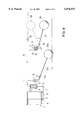
- FIGS. 7A, 7B, 7C, and 7D variations of float, cylinder and valve arrangements with different positions of the float arm pivot points
- FIG. 8 another implementation form where an additional float is provided for operating the valves
- FIG. 9 another implementation form where the rinsing fixture is designed as a raisable and lowerable container that in its lowered position can be held fixed to the floor of the storage space by means of the locking fixture and
- FIG. 10 a section through a check valve modified according to the invention.
- FIG. 1A shows a rectangular cut-off flap 1 that serves the closing off of a corresponding rectangular inlet opening of a rinsing chamber.
- the cut-off flap 1 is attached to an outer wall of the rinsing chamber so as to be pivotable around an upper horizontal axis 2.
- a storage space is connected to the rinsing chamber, so that after the emptying of the storage space the latter can be rinsed out by means of the liquid accumulated in the rinsing chamber, if the cut-off flap 1 is opened.
- the cut-off flap 1 is provided with lugs 3 that project beyond it downward, which can be brought into working connection with a closing mechanism 5 that is likewise connected to the outlet wall 4.
- the closing mechanism 5 can for example show a pivotable shaft 7 with lugs 6, which lugs, when the cut-off flap 1 is in the closed position, i.e., when the flap 1 is in the vertical position, are tilted so that they engage the lugs 3 from behind and thus press the cut-off flap 1 against the wall 4 or against its frame and prevent a swinging away of the cut-off flap 1 from the rinsing chamber opening.
- the closing mechanism 5 can, for example, also be designed as a pusher construction, as is described, for example, in DE 37 18 812 A1. The closing mechanism 5 is moved, i.e., the shaft 7 is rotated or a bolt is pushed, by means of a bellows 8 that is carried in a cylinder 9.
- a pipe 11 is connected to the internal space 10 of the cylinder 9, which pipe leads to a check valve 12 and from this another pipe 13 leads to the inner space 14 of another cylinder 15 into which a bellows 16 leads.
- the basically free passage direction of the check valve 12 is from the pipe 11 arranged with the cylinder 9 into the pipe 13 arranged with cylinder 15.
- Shown is the valve seat 17 for check valve 12 and the ball 18 that works in conjunction with this.
- Located in the housing 19 of the check valve 12 is plunger 20 that is mounted in such a way that it can be pushed and that, in the position of having been driven into the housing 19, lifts the ball 18 from the valve seat 17 and thus enables passage in both directions through the valve 12.
- the ball 18 is spring loaded by means of a spring 21 in the direction of the valve seat 17.
- a relatively strong pressure spring 22 that spring loads the bellows 16 in the direction of the pipe 13.
- a relatively weak pressure spring 23 that spring loads the bellows 8 in the direction of pipe 11.
- a rod 24 Leading out of the cylinder 15 and connected with bellows 16 is a rod 24 that leads through an opening, not shown in detail, in a float rod 25 formed as a lever.
- the rod 24 is provided with a pivotable drive plate 26 on the side that is turned away from the cylinder 15, which plate engages the float rod 25 from behind.
- a rod 27 connected with the bellows 8 of cylinder 9, which rod 27 leads out of the cylinder housing 10 and drives the movable component that effects the closing process, either directly by a translational motion or through conversion of the translational motion to rotary motion.
- the float rod 25 in the region of one end carries a ball-shaped or cylinder-shaped float 28 and can be pivoted around an axis 29.
- the lever arm of the float rod 25 opposite the float 28 contacts the plunger 20 of the check valve 12, so that the ball 18 is raised from the valve seat 17.
- FIG. 1A shows clearly the flap 1 with the lugs 6 of the closing mechanism 5 that release the lugs 3.
- a mounting plate shown in dashed lines is indicated by the reference numeral 37.
- the plate provides the stationary mounting for the bearing axis 29, the float rod 25, the cylinder 15 and the check valve 12.
- FIG. 1C shows the condition where the closing mechanism 5 has been transferred into its locking position in which the lugs 6 of the closing mechanism 5 engage the lugs 3 of the cut-off flap 1 in such a way that the cut-off flap 1 is completely pressed against the outlet wall 4 of the rinsing chamber or against its frame.
- FIGS. 2A through 2C show the steps in the opening of closing mechanism 5.
- the condition of the closing mechanism 5 according to the representation in FIG. 2A corresponds to that of the representation in 1C. If The liquid level in the storage space and thus the float 28 sinks, the float rod 25 pivots back, whereby due to the closed position of the check valve 12 the spring-loaded bellows 8 and 16 of cylinders 9 and 15 remain in their positions, while the float rod 25 moves relative to the rod 24 that passes through it.
- FIG. 2B shows the partially sunken float 28 and the condition of the cut-off flap 1 shortly before its opening.
- the float rod 25 has reached an angle at which it contacts the plunger 20 of the check valve 12 and thus lifts the ball 18 of the check valve 12 from its seat 17.
- the hydraulic fluid can enter through the pipes 11 and 13 into the inner space 10 of cylinder 9 and it presses the bellows 8 located there against the force of the weaker spring 23 acting on it.
- FIG. 4 shows a configuration of the invention by which a multiplicity of cutoff flaps 1 can be operated.
- a cylinder 9 and 15 associated with each cut-off flap 1 are a cylinder 9 and 15, a check valve 12, and pipes 11 and 13.
- This implementation form also shows the pressure springs 22 and 23.
- a wall is indicated by the reference numeral 36 on which the float rod 25 with float 28 is attached so that it can pivot.
- FIG. 4a is to be seen in the context of the representation of FIG.
- FIG. 5 shows a tilt-rinsing fixture whereby the actual rinsing container 32 can be pivoted on an axis 33 that is not arranged at the center of gravity of the rinsing container 32 so that after emptying the rinsing container 32 automatically rights itself into the position shown in FIG. 5.
- the rinsing container 32 is arranged above the floor of the storage space for liquid and is, for example, filled with stored liquid.
- the locking mechanism 35 is provided for; it is constructed in the simplest manner through the slideable piston rod 27 of cylinder 9 and in an end position prevents the rinsing chamber 32 from tipping.
- FIGS. 1a through 1c and 2a through 2c reference can be made to the implementation in FIGS. 1a through 1c and 2a through 2c, with the basic difference that with the implementation form according to FIG. 5 a pressure spring 23 is arranged in the cylinder 9 associated with rinsing container 32, which spring is relatively strong, while the spring 22 arranged in the other cylinder 15 is relatively weak, and further, that by way of a single-armed float rod 25 with the raising of the float 28 the space for hydraulic fluid in cylinder 15 is decreased through the compression of bellows 16 in cylinder 15 and correspondingly the space in cylinder 9 is increased by expansion of the bellows 8, and further that the check valve 12 is passed through in the opposite direction so that it closes off the flow from pipes 11 and 13 when the plunger 20 is not operated.
- FIG. 6 shows a variant based on the implementation form according to FIG. 5 in which the pipe 11 separates into two sections 11a and 11b that lead to cylinders 9 and that work in conjunction with two rinsing containers 32.
- each rinsing container 32 is provided with a counterweight 34 that assures that the rinsing container 32 associated with it, after the emptying, rights itself automatically into the position shown in FIG. 6.
- a large-volume cylinder 15 is used that works together with two cylinders 9 that show a smaller volume.
- FIGS. 7A through 7D show variations of float, cylinder, and valve arrangements with different locations of the float-arm pivot point for application with the different types of rinsing fixtures.
- FIG. 8 shows a modified implementation form where provision is made for an additional float 28a, which is taken up by a float rod 25a that can pivot about an axis 29a.
- This auxiliary float effects the opening of the check valve 12 upon complete or nearly complete emptying of the storage space, since the section of the float rod 25a that overhangs the axis 29a pushes the plunger 20 of the check valve 12 and transfers this into its opened position.
- the method of operation of this implementation form is identical with the implementation form according to FIGS. 1a through 1c and 2a through 2c with the difference that there the float 28 takes on the function of floats 28 and 28a according to the implementation form of FIG 8.
- FIG. 10 shows a detailed representation of the valve 12 as described in relation to the previous implementation forms.
- This shows a displaceable plunger 20 for lifting from its associated seat 17 the ball 18 that closes off the passage through the valve.
- the plunger 20 is connected with an elastic steel membrane 45 that is held in a sealed fashion in the valve housing 46.
- float rod 25 or, in the case of the implementation form according to FIG. 8, by means of float rod 25a, the steel membrane 45 and thus the plunger 20 are pushed against the force of the coil pressure spring 21 and release the check valve 12 from its closing-off position.
Landscapes
- Health & Medical Sciences (AREA)
- Life Sciences & Earth Sciences (AREA)
- Engineering & Computer Science (AREA)
- Hydrology & Water Resources (AREA)
- Public Health (AREA)
- Water Supply & Treatment (AREA)
- Float Valves (AREA)
- Moulds For Moulding Plastics Or The Like (AREA)
- Sampling And Sample Adjustment (AREA)
- Bidet-Like Cleaning Device And Other Flush Toilet Accessories (AREA)
- Cleaning By Liquid Or Steam (AREA)
- Devices For Medical Bathing And Washing (AREA)
Applications Claiming Priority (2)
| Application Number | Priority Date | Filing Date | Title |
|---|---|---|---|
| DE19735592A DE19735592C2 (de) | 1997-08-15 | 1997-08-15 | Vorrichtung zum Betätigen eines Mechanismus einer Spüleinrichtung |
| DE19735592 | 1997-08-15 |
Publications (1)
| Publication Number | Publication Date |
|---|---|
| US6076547A true US6076547A (en) | 2000-06-20 |
Family
ID=7839200
Family Applications (1)
| Application Number | Title | Priority Date | Filing Date |
|---|---|---|---|
| US09/134,844 Expired - Fee Related US6076547A (en) | 1997-08-15 | 1998-08-14 | Device for operating a mechanism of a rinsing fixture |
Country Status (5)
| Country | Link |
|---|---|
| US (1) | US6076547A (fr) |
| EP (1) | EP0898025B1 (fr) |
| AT (1) | ATE205564T1 (fr) |
| CA (1) | CA2244938A1 (fr) |
| DE (2) | DE19735592C2 (fr) |
Cited By (1)
| Publication number | Priority date | Publication date | Assignee | Title |
|---|---|---|---|---|
| US20090199910A1 (en) * | 2008-02-07 | 2009-08-13 | William Garry Brown | Robust water level control valve |
Families Citing this family (2)
| Publication number | Priority date | Publication date | Assignee | Title |
|---|---|---|---|---|
| DE19912724A1 (de) * | 1999-03-20 | 2000-10-05 | Karl Kraus | Verfahren zum Reinigen eines Flüssigkeitsspeicherraums, Flüssigkeitsspeicherraum und Spültrommel |
| DE20011585U1 (de) | 2000-07-03 | 2000-11-23 | bgu-Umweltschutzanlagen GmbH, 74626 Bretzfeld | Pneumatische Schaltung zur Betätigung eines Pneumatikzylinders und pneumatische Spüleinrichtung für Abwasserdrosselorgane |
Citations (6)
| Publication number | Priority date | Publication date | Assignee | Title |
|---|---|---|---|---|
| US1707926A (en) * | 1929-04-02 | Eloat-controlled device | ||
| US1759663A (en) * | 1929-02-05 | 1930-05-20 | Aqua Systems Inc | Means for controlling the flow in hydraulic oil storing and dispensing systems |
| US1764825A (en) * | 1927-09-27 | 1930-06-17 | Fisher Governor Company Inc | Remote-control structure for valves |
| US2790459A (en) * | 1953-01-06 | 1957-04-30 | Trist & Co Ltd Ronald | Relay mechanism |
| US3860028A (en) * | 1973-01-22 | 1975-01-14 | Atlas Valve Company | Fluid level control system and fluid level actuated controller therefor |
| US5249745A (en) * | 1991-09-19 | 1993-10-05 | Giacomo Bertolotti | Fluid distribution system |
Family Cites Families (11)
| Publication number | Priority date | Publication date | Assignee | Title |
|---|---|---|---|---|
| DE3121520A1 (de) * | 1981-05-29 | 1982-12-23 | Ahmed Cevdet 9008 St. Gallen Saatci | Eirichtung zur fluessigkeitsspuelung von behaeltern, insbeosndere abwasserbehaeltern |
| CH654867A5 (de) * | 1982-02-23 | 1986-03-14 | Nill Werner | Becken mit steuervorrichtung zur ausloesung von regulier- und/oder schaltvorgaengen. |
| DE3418714A1 (de) * | 1984-05-19 | 1985-11-21 | Oskar Vollmar GmbH, 7000 Stuttgart | Anlage zum versorgen einer reinigungseinrichtung fuer regenbecken oder dergl. mit spuelwasser |
| EP0211058B1 (fr) * | 1985-02-02 | 1988-09-21 | Giehl, Klaus Ulrich, Dipl.-Ing. (FH) | Espace de retenue de liquide avec dispositif de rincage |
| GB2189870A (en) * | 1986-04-25 | 1987-11-04 | Ye Chain Lin | Valve incorporating a float body |
| DE3718812A1 (de) * | 1987-06-05 | 1988-12-15 | Lothar Steinhardt | Verfahren zum betaetigen des schliessmechanismuses einer schwimmergesteuerten absperrklappe einer spuelkammer zum spuelen eines fluessigkeitsspeicherraumes sowie vorrichtung zur durchfuehrung des verfahrens |
| DE3906182A1 (de) * | 1989-02-28 | 1990-08-30 | Klein Schanzlin & Becker Ag | Verfahren zur steuerung von beckenreinigungs- und entleerungseinrichtungen |
| DE4038622C2 (de) * | 1989-12-14 | 1997-01-30 | Vollmar Oskar Gmbh | Verfahren und Anlage zum Reinigen eines Regenbeckens |
| DE4029603C3 (de) * | 1990-09-19 | 1997-05-07 | Feluwa Pumpen Gmbh | Fördervorrichtung für mit Sperrstoffen versetzte flüssige Medien, insbesondere Abwässer |
| DE4342612A1 (de) * | 1993-12-14 | 1995-06-22 | Steinhardt Lothar | Spülvorrichtung |
| DE19533483A1 (de) * | 1995-09-12 | 1997-03-13 | Steinhardt Lothar | Verfahren und Vorrichtung zum Spülen eines Flüssigkeitsspeicherraumes |
-
1997
- 1997-08-15 DE DE19735592A patent/DE19735592C2/de not_active Expired - Fee Related
-
1998
- 1998-07-25 AT AT98113951T patent/ATE205564T1/de not_active IP Right Cessation
- 1998-07-25 EP EP98113951A patent/EP0898025B1/fr not_active Expired - Lifetime
- 1998-07-25 DE DE59801432T patent/DE59801432D1/de not_active Expired - Fee Related
- 1998-08-12 CA CA002244938A patent/CA2244938A1/fr not_active Abandoned
- 1998-08-14 US US09/134,844 patent/US6076547A/en not_active Expired - Fee Related
Patent Citations (6)
| Publication number | Priority date | Publication date | Assignee | Title |
|---|---|---|---|---|
| US1707926A (en) * | 1929-04-02 | Eloat-controlled device | ||
| US1764825A (en) * | 1927-09-27 | 1930-06-17 | Fisher Governor Company Inc | Remote-control structure for valves |
| US1759663A (en) * | 1929-02-05 | 1930-05-20 | Aqua Systems Inc | Means for controlling the flow in hydraulic oil storing and dispensing systems |
| US2790459A (en) * | 1953-01-06 | 1957-04-30 | Trist & Co Ltd Ronald | Relay mechanism |
| US3860028A (en) * | 1973-01-22 | 1975-01-14 | Atlas Valve Company | Fluid level control system and fluid level actuated controller therefor |
| US5249745A (en) * | 1991-09-19 | 1993-10-05 | Giacomo Bertolotti | Fluid distribution system |
Cited By (1)
| Publication number | Priority date | Publication date | Assignee | Title |
|---|---|---|---|---|
| US20090199910A1 (en) * | 2008-02-07 | 2009-08-13 | William Garry Brown | Robust water level control valve |
Also Published As
| Publication number | Publication date |
|---|---|
| EP0898025B1 (fr) | 2001-09-12 |
| DE59801432D1 (de) | 2001-10-18 |
| CA2244938A1 (fr) | 1999-02-15 |
| DE19735592A1 (de) | 1999-03-04 |
| DE19735592C2 (de) | 2000-06-29 |
| ATE205564T1 (de) | 2001-09-15 |
| EP0898025A1 (fr) | 1999-02-24 |
Similar Documents
| Publication | Publication Date | Title |
|---|---|---|
| US5495890A (en) | Float operated pneumatic pump | |
| US4838025A (en) | Hydraulic motor with buoyant tubular members | |
| US5645102A (en) | Leak resistant, switching, double valve system | |
| US5287882A (en) | Ball cock assembly float with drain openings | |
| US6076547A (en) | Device for operating a mechanism of a rinsing fixture | |
| US6095759A (en) | Submersible pump having float actuated valve | |
| US5655565A (en) | Above-ground tank auto-limiter | |
| US4577654A (en) | Fluid actuated pipeline valve | |
| JP2002517680A (ja) | 安全弁の制御装置 | |
| EP1841968B1 (fr) | Dispositif de transport de liquides par vapeur ou air comprime | |
| JP2020002560A (ja) | 定水位弁装置 | |
| RU46575U1 (ru) | Мобильная передвижная установка для измерения дебита продукции скважин | |
| KR102239368B1 (ko) | 증기 보일러 무동력 급수장치 | |
| CA2185310C (fr) | Dispositif pour le rincage d'un reservoir de stockage de liquide | |
| SU1629242A1 (ru) | Устройство дл ограничени уровн налива жидкостей | |
| US2780236A (en) | Locking and releasing mechanism for float controlled pilot valve | |
| RU2248487C1 (ru) | Сливной клапан | |
| JP3349532B2 (ja) | 貯液槽の液面制御装置 | |
| USRE14198E (en) | Flttshometer | |
| JP4149465B2 (ja) | サイホン配管内の滞留空気排出装置 | |
| JP2022114501A (ja) | 定水位弁装置 | |
| SU1290132A1 (ru) | Стенд дл испытани гидроцилиндров самосвалов | |
| RU2173808C2 (ru) | Отсечной кран | |
| US1722471A (en) | Sewer-flushing device | |
| RU2248488C1 (ru) | Сливной клапан |
Legal Events
| Date | Code | Title | Description |
|---|---|---|---|
| FEPP | Fee payment procedure |
Free format text: PAYOR NUMBER ASSIGNED (ORIGINAL EVENT CODE: ASPN); ENTITY STATUS OF PATENT OWNER: SMALL ENTITY |
|
| LAPS | Lapse for failure to pay maintenance fees | ||
| FP | Lapsed due to failure to pay maintenance fee |
Effective date: 20040620 |
|
| STCH | Information on status: patent discontinuation |
Free format text: PATENT EXPIRED DUE TO NONPAYMENT OF MAINTENANCE FEES UNDER 37 CFR 1.362 |