US6033793A - Integrated power module - Google Patents
Integrated power module Download PDFInfo
- Publication number
- US6033793A US6033793A US09/032,625 US3262598A US6033793A US 6033793 A US6033793 A US 6033793A US 3262598 A US3262598 A US 3262598A US 6033793 A US6033793 A US 6033793A
- Authority
- US
- United States
- Prior art keywords
- gas
- fuel
- power module
- reformer
- inlet
- Prior art date
- Legal status (The legal status is an assumption and is not a legal conclusion. Google has not performed a legal analysis and makes no representation as to the accuracy of the status listed.)
- Expired - Fee Related
Links
- 239000000446 fuel Substances 0.000 claims abstract description 217
- 239000007789 gas Substances 0.000 claims abstract description 195
- UFHFLCQGNIYNRP-UHFFFAOYSA-N Hydrogen Chemical compound [H][H] UFHFLCQGNIYNRP-UHFFFAOYSA-N 0.000 claims abstract description 50
- 239000001257 hydrogen Substances 0.000 claims abstract description 43
- 229910052739 hydrogen Inorganic materials 0.000 claims abstract description 43
- 238000002485 combustion reaction Methods 0.000 claims abstract description 32
- QVGXLLKOCUKJST-UHFFFAOYSA-N atomic oxygen Chemical compound [O] QVGXLLKOCUKJST-UHFFFAOYSA-N 0.000 claims abstract description 26
- 239000001301 oxygen Substances 0.000 claims abstract description 26
- 229910052760 oxygen Inorganic materials 0.000 claims abstract description 26
- 238000006243 chemical reaction Methods 0.000 claims abstract description 18
- XLYOFNOQVPJJNP-UHFFFAOYSA-N water Substances O XLYOFNOQVPJJNP-UHFFFAOYSA-N 0.000 claims abstract description 17
- 238000010438 heat treatment Methods 0.000 claims abstract description 10
- 230000000694 effects Effects 0.000 claims abstract description 7
- 238000000034 method Methods 0.000 claims description 37
- 230000006835 compression Effects 0.000 claims description 30
- 238000007906 compression Methods 0.000 claims description 30
- 230000008569 process Effects 0.000 claims description 24
- 239000000203 mixture Substances 0.000 claims description 23
- CURLTUGMZLYLDI-UHFFFAOYSA-N Carbon dioxide Chemical compound O=C=O CURLTUGMZLYLDI-UHFFFAOYSA-N 0.000 claims description 14
- 239000012528 membrane Substances 0.000 claims description 13
- 238000007254 oxidation reaction Methods 0.000 claims description 11
- 238000012546 transfer Methods 0.000 claims description 10
- UGFAIRIUMAVXCW-UHFFFAOYSA-N Carbon monoxide Chemical compound [O+]#[C-] UGFAIRIUMAVXCW-UHFFFAOYSA-N 0.000 claims description 9
- 229910002091 carbon monoxide Inorganic materials 0.000 claims description 9
- 239000001569 carbon dioxide Substances 0.000 claims description 8
- 229910002092 carbon dioxide Inorganic materials 0.000 claims description 8
- 239000000919 ceramic Substances 0.000 claims description 7
- 238000009792 diffusion process Methods 0.000 claims description 7
- 239000003792 electrolyte Substances 0.000 claims description 7
- 238000002347 injection Methods 0.000 claims description 7
- 239000007924 injection Substances 0.000 claims description 7
- 238000003487 electrochemical reaction Methods 0.000 claims description 5
- BVKZGUZCCUSVTD-UHFFFAOYSA-L Carbonate Chemical compound [O-]C([O-])=O BVKZGUZCCUSVTD-UHFFFAOYSA-L 0.000 claims description 2
- 239000003623 enhancer Substances 0.000 claims description 2
- -1 steam Substances 0.000 claims 2
- VUZPPFZMUPKLLV-UHFFFAOYSA-N methane;hydrate Chemical compound C.O VUZPPFZMUPKLLV-UHFFFAOYSA-N 0.000 claims 1
- 239000000047 product Substances 0.000 abstract description 31
- 238000004519 manufacturing process Methods 0.000 abstract description 7
- 238000000746 purification Methods 0.000 abstract description 5
- 239000007795 chemical reaction product Substances 0.000 abstract description 4
- 230000001590 oxidative effect Effects 0.000 abstract description 2
- 230000004888 barrier function Effects 0.000 description 16
- VNWKTOKETHGBQD-UHFFFAOYSA-N methane Chemical compound C VNWKTOKETHGBQD-UHFFFAOYSA-N 0.000 description 12
- 238000001816 cooling Methods 0.000 description 11
- 238000009413 insulation Methods 0.000 description 8
- 238000002156 mixing Methods 0.000 description 8
- 230000003647 oxidation Effects 0.000 description 8
- 230000008901 benefit Effects 0.000 description 7
- 238000013461 design Methods 0.000 description 7
- 230000004048 modification Effects 0.000 description 7
- 238000012986 modification Methods 0.000 description 7
- 230000001965 increasing effect Effects 0.000 description 6
- 238000009826 distribution Methods 0.000 description 5
- 230000005611 electricity Effects 0.000 description 5
- 238000005516 engineering process Methods 0.000 description 5
- 150000002431 hydrogen Chemical class 0.000 description 4
- 230000000171 quenching effect Effects 0.000 description 4
- 238000002407 reforming Methods 0.000 description 4
- LFQSCWFLJHTTHZ-UHFFFAOYSA-N Ethanol Chemical compound CCO LFQSCWFLJHTTHZ-UHFFFAOYSA-N 0.000 description 3
- OKKJLVBELUTLKV-UHFFFAOYSA-N Methanol Chemical compound OC OKKJLVBELUTLKV-UHFFFAOYSA-N 0.000 description 3
- 239000006227 byproduct Substances 0.000 description 3
- 230000001419 dependent effect Effects 0.000 description 3
- 230000002708 enhancing effect Effects 0.000 description 3
- 239000002737 fuel gas Substances 0.000 description 3
- 238000002955 isolation Methods 0.000 description 3
- 238000010791 quenching Methods 0.000 description 3
- 238000011084 recovery Methods 0.000 description 3
- 239000007787 solid Substances 0.000 description 3
- IJGRMHOSHXDMSA-UHFFFAOYSA-N Atomic nitrogen Chemical compound N#N IJGRMHOSHXDMSA-UHFFFAOYSA-N 0.000 description 2
- 238000013459 approach Methods 0.000 description 2
- 230000008602 contraction Effects 0.000 description 2
- 238000010586 diagram Methods 0.000 description 2
- 150000002500 ions Chemical class 0.000 description 2
- 239000000463 material Substances 0.000 description 2
- 229910052751 metal Inorganic materials 0.000 description 2
- 239000002184 metal Substances 0.000 description 2
- 239000003345 natural gas Substances 0.000 description 2
- 230000001737 promoting effect Effects 0.000 description 2
- 239000012264 purified product Substances 0.000 description 2
- 238000007086 side reaction Methods 0.000 description 2
- OKTJSMMVPCPJKN-UHFFFAOYSA-N Carbon Chemical compound [C] OKTJSMMVPCPJKN-UHFFFAOYSA-N 0.000 description 1
- 208000035859 Drug effect increased Diseases 0.000 description 1
- 101100293261 Mus musculus Naa15 gene Proteins 0.000 description 1
- 230000001154 acute effect Effects 0.000 description 1
- 238000003491 array Methods 0.000 description 1
- 230000015572 biosynthetic process Effects 0.000 description 1
- 230000000740 bleeding effect Effects 0.000 description 1
- 229910052799 carbon Inorganic materials 0.000 description 1
- 239000003054 catalyst Substances 0.000 description 1
- 239000011248 coating agent Substances 0.000 description 1
- 238000000576 coating method Methods 0.000 description 1
- 239000000470 constituent Substances 0.000 description 1
- 238000010276 construction Methods 0.000 description 1
- 238000010292 electrical insulation Methods 0.000 description 1
- 230000008030 elimination Effects 0.000 description 1
- 238000003379 elimination reaction Methods 0.000 description 1
- 238000005265 energy consumption Methods 0.000 description 1
- 230000007613 environmental effect Effects 0.000 description 1
- 239000003344 environmental pollutant Substances 0.000 description 1
- 238000001704 evaporation Methods 0.000 description 1
- 230000008020 evaporation Effects 0.000 description 1
- 239000011094 fiberboard Substances 0.000 description 1
- 239000012530 fluid Substances 0.000 description 1
- 239000006260 foam Substances 0.000 description 1
- 239000003502 gasoline Substances 0.000 description 1
- 238000007689 inspection Methods 0.000 description 1
- 239000011810 insulating material Substances 0.000 description 1
- 230000010354 integration Effects 0.000 description 1
- 239000011872 intimate mixture Substances 0.000 description 1
- 239000003350 kerosene Substances 0.000 description 1
- 239000007788 liquid Substances 0.000 description 1
- 238000012423 maintenance Methods 0.000 description 1
- 229910044991 metal oxide Inorganic materials 0.000 description 1
- 150000004706 metal oxides Chemical class 0.000 description 1
- 229910052757 nitrogen Inorganic materials 0.000 description 1
- 231100000719 pollutant Toxicity 0.000 description 1
- 239000012495 reaction gas Substances 0.000 description 1
- 230000001172 regenerating effect Effects 0.000 description 1
- 230000008439 repair process Effects 0.000 description 1
- 230000002269 spontaneous effect Effects 0.000 description 1
- 229910001220 stainless steel Inorganic materials 0.000 description 1
- 239000010935 stainless steel Substances 0.000 description 1
- 239000013589 supplement Substances 0.000 description 1
- 238000011144 upstream manufacturing Methods 0.000 description 1
- 238000009834 vaporization Methods 0.000 description 1
- 230000008016 vaporization Effects 0.000 description 1
Images
Classifications
-
- F—MECHANICAL ENGINEERING; LIGHTING; HEATING; WEAPONS; BLASTING
- F23—COMBUSTION APPARATUS; COMBUSTION PROCESSES
- F23D—BURNERS
- F23D11/00—Burners using a direct spraying action of liquid droplets or vaporised liquid into the combustion space
- F23D11/36—Details, e.g. burner cooling means, noise reduction means
- F23D11/44—Preheating devices; Vaporising devices
- F23D11/441—Vaporising devices incorporated with burners
- F23D11/443—Vaporising devices incorporated with burners heated by the main burner flame
-
- F—MECHANICAL ENGINEERING; LIGHTING; HEATING; WEAPONS; BLASTING
- F23—COMBUSTION APPARATUS; COMBUSTION PROCESSES
- F23D—BURNERS
- F23D14/00—Burners for combustion of a gas, e.g. of a gas stored under pressure as a liquid
- F23D14/20—Non-premix gas burners, i.e. in which gaseous fuel is mixed with combustion air on arrival at the combustion zone
- F23D14/22—Non-premix gas burners, i.e. in which gaseous fuel is mixed with combustion air on arrival at the combustion zone with separate air and gas feed ducts, e.g. with ducts running parallel or crossing each other
-
- H—ELECTRICITY
- H01—ELECTRIC ELEMENTS
- H01M—PROCESSES OR MEANS, e.g. BATTERIES, FOR THE DIRECT CONVERSION OF CHEMICAL ENERGY INTO ELECTRICAL ENERGY
- H01M8/00—Fuel cells; Manufacture thereof
- H01M8/04—Auxiliary arrangements, e.g. for control of pressure or for circulation of fluids
-
- H—ELECTRICITY
- H01—ELECTRIC ELEMENTS
- H01M—PROCESSES OR MEANS, e.g. BATTERIES, FOR THE DIRECT CONVERSION OF CHEMICAL ENERGY INTO ELECTRICAL ENERGY
- H01M8/00—Fuel cells; Manufacture thereof
- H01M8/06—Combination of fuel cells with means for production of reactants or for treatment of residues
- H01M8/0606—Combination of fuel cells with means for production of reactants or for treatment of residues with means for production of gaseous reactants
- H01M8/0612—Combination of fuel cells with means for production of reactants or for treatment of residues with means for production of gaseous reactants from carbon-containing material
- H01M8/0625—Combination of fuel cells with means for production of reactants or for treatment of residues with means for production of gaseous reactants from carbon-containing material in a modular combined reactor/fuel cell structure
-
- H—ELECTRICITY
- H01—ELECTRIC ELEMENTS
- H01M—PROCESSES OR MEANS, e.g. BATTERIES, FOR THE DIRECT CONVERSION OF CHEMICAL ENERGY INTO ELECTRICAL ENERGY
- H01M8/00—Fuel cells; Manufacture thereof
- H01M8/06—Combination of fuel cells with means for production of reactants or for treatment of residues
- H01M8/0662—Treatment of gaseous reactants or gaseous residues, e.g. cleaning
-
- H—ELECTRICITY
- H01—ELECTRIC ELEMENTS
- H01M—PROCESSES OR MEANS, e.g. BATTERIES, FOR THE DIRECT CONVERSION OF CHEMICAL ENERGY INTO ELECTRICAL ENERGY
- H01M8/00—Fuel cells; Manufacture thereof
- H01M8/24—Grouping of fuel cells, e.g. stacking of fuel cells
- H01M8/2465—Details of groupings of fuel cells
- H01M8/247—Arrangements for tightening a stack, for accommodation of a stack in a tank or for assembling different tanks
-
- H—ELECTRICITY
- H01—ELECTRIC ELEMENTS
- H01M—PROCESSES OR MEANS, e.g. BATTERIES, FOR THE DIRECT CONVERSION OF CHEMICAL ENERGY INTO ELECTRICAL ENERGY
- H01M8/00—Fuel cells; Manufacture thereof
- H01M8/10—Fuel cells with solid electrolytes
- H01M8/12—Fuel cells with solid electrolytes operating at high temperature, e.g. with stabilised ZrO2 electrolyte
- H01M2008/1293—Fuel cells with solid oxide electrolytes
-
- H—ELECTRICITY
- H01—ELECTRIC ELEMENTS
- H01M—PROCESSES OR MEANS, e.g. BATTERIES, FOR THE DIRECT CONVERSION OF CHEMICAL ENERGY INTO ELECTRICAL ENERGY
- H01M8/00—Fuel cells; Manufacture thereof
- H01M8/14—Fuel cells with fused electrolytes
- H01M2008/147—Fuel cells with molten carbonates
-
- H—ELECTRICITY
- H01—ELECTRIC ELEMENTS
- H01M—PROCESSES OR MEANS, e.g. BATTERIES, FOR THE DIRECT CONVERSION OF CHEMICAL ENERGY INTO ELECTRICAL ENERGY
- H01M2300/00—Electrolytes
- H01M2300/0017—Non-aqueous electrolytes
- H01M2300/0048—Molten electrolytes used at high temperature
- H01M2300/0051—Carbonates
-
- H—ELECTRICITY
- H01—ELECTRIC ELEMENTS
- H01M—PROCESSES OR MEANS, e.g. BATTERIES, FOR THE DIRECT CONVERSION OF CHEMICAL ENERGY INTO ELECTRICAL ENERGY
- H01M2300/00—Electrolytes
- H01M2300/0017—Non-aqueous electrolytes
- H01M2300/0065—Solid electrolytes
- H01M2300/0068—Solid electrolytes inorganic
- H01M2300/0071—Oxides
- H01M2300/0074—Ion conductive at high temperature
-
- H—ELECTRICITY
- H01—ELECTRIC ELEMENTS
- H01M—PROCESSES OR MEANS, e.g. BATTERIES, FOR THE DIRECT CONVERSION OF CHEMICAL ENERGY INTO ELECTRICAL ENERGY
- H01M8/00—Fuel cells; Manufacture thereof
- H01M8/04—Auxiliary arrangements, e.g. for control of pressure or for circulation of fluids
- H01M8/04007—Auxiliary arrangements, e.g. for control of pressure or for circulation of fluids related to heat exchange
- H01M8/04014—Heat exchange using gaseous fluids; Heat exchange by combustion of reactants
- H01M8/04022—Heating by combustion
-
- Y—GENERAL TAGGING OF NEW TECHNOLOGICAL DEVELOPMENTS; GENERAL TAGGING OF CROSS-SECTIONAL TECHNOLOGIES SPANNING OVER SEVERAL SECTIONS OF THE IPC; TECHNICAL SUBJECTS COVERED BY FORMER USPC CROSS-REFERENCE ART COLLECTIONS [XRACs] AND DIGESTS
- Y02—TECHNOLOGIES OR APPLICATIONS FOR MITIGATION OR ADAPTATION AGAINST CLIMATE CHANGE
- Y02E—REDUCTION OF GREENHOUSE GAS [GHG] EMISSIONS, RELATED TO ENERGY GENERATION, TRANSMISSION OR DISTRIBUTION
- Y02E60/00—Enabling technologies; Technologies with a potential or indirect contribution to GHG emissions mitigation
- Y02E60/30—Hydrogen technology
- Y02E60/50—Fuel cells
-
- Y—GENERAL TAGGING OF NEW TECHNOLOGICAL DEVELOPMENTS; GENERAL TAGGING OF CROSS-SECTIONAL TECHNOLOGIES SPANNING OVER SEVERAL SECTIONS OF THE IPC; TECHNICAL SUBJECTS COVERED BY FORMER USPC CROSS-REFERENCE ART COLLECTIONS [XRACs] AND DIGESTS
- Y02—TECHNOLOGIES OR APPLICATIONS FOR MITIGATION OR ADAPTATION AGAINST CLIMATE CHANGE
- Y02P—CLIMATE CHANGE MITIGATION TECHNOLOGIES IN THE PRODUCTION OR PROCESSING OF GOODS
- Y02P70/00—Climate change mitigation technologies in the production process for final industrial or consumer products
- Y02P70/50—Manufacturing or production processes characterised by the final manufactured product
Definitions
- the present invention relates generally to a power module which produces electrical current as well as heat, and which can be used for various purposes, including driving a turbine or heating a dwelling or workplace. More specifically, the present invention is an integrated module that utilizes a partial oxidizing reactor (reformer) for producing hydrogen, which is subsequently used to generate electrical current by way of a fuel cell stack. Excess hydrogen and gas product may then be used to produce additional heat in a combustion chamber downstream of the fuel cell. Alternatively, the fuel cell can be substituted with an electrochemical reactor or diffusion membrane which is designed to further process the partial oxidation product gas for downstream equipment or to purify the product gas.
- a partial oxidizing reactor reformer
- the fuel cell can be substituted with an electrochemical reactor or diffusion membrane which is designed to further process the partial oxidation product gas for downstream equipment or to purify the product gas.
- the present invention obviates the foregoing problems and difficulties, and provides a combined source of heat and electrical power that is substantially pollution-free.
- a single, integrated module is provided, the module having simplified internal heat transfer and component integration to achieve a cost-effective system. Further, utilization of incoming fuel is staged to concurrently minimize emissions and maximize efficiency.
- such objectives are achieved in a small, modular power generator that can serve as an energy source for residential appliances, commercial equipment, and industrial processes.
- the stages of the unit are integrated thermally so that the inlet process gases provide cooling to various downstream components while also providing regenerative preheating for higher temperature upstream components.
- the staged consumption of fuel first involves a partial oxidation reformer process which operates at a fuel-rich level (i.e., air/fuel stoichiometric ratio less than about 0.8) to create a hydrogen-containing gas stream that is subsequently processed by downstream stages.
- the air/fuel stoichiometric ratio in the reformer process is preferably between about 0.1 and 0.7, and is most preferably between about 0.2 and 0.4.
- the second stage is a stoichiometrically-balanced region, where fuel is reacted with oxygen electrochemically for high-efficiency conversion to electricity, without unwanted side reactions that create pollution in conventional combustion equipment.
- the third stage consumes any remaining fuel in a fuel-lean (i.e., air/fuel stoichiometric ratio greater than about 1.1) combustor.
- the air/fuel stoichiometric ratio in the third stage combustor is preferably above about 1.4.
- This third stage not only ensures the elimination of all non-reacted fuel, but also generates additional thermal energy which can be useful in a number of applications.
- the final stage does not create unwanted pollution (e.g., thermal NO x ) because the hydrogen present in the fuel stream allows stable operation at these high stoichiometric ratios.
- the second stage comprises a fuel cell for the generation of electrical current.
- a compression spring or a set of compression springs may be used to exert a mechanical force on the fuel cell.
- a particular advantage of the present invention is the integrated design and structure of the power module that effects both preheating of the process gas and cooling of the product gas, as well as the components of the unit within the three stages, while minimizing interface complexities and equipment.
- cool inlet process gases enter the module and provide cooling to the fuel cell module and associated fuel cell compression hardware, while simultaneously providing preheating of the process gases for both the fuel cell and the reformer reaction, thereby increasing efficiency.
- additional preheating is achieved in parallel with reformer product gas cooling.
- One embodiment would increase the air flow to achieve sufficient cooling of reformer product gases prior to introduction into the fuel cell. This excess air could then bypass the reformer and the fuel cell and enter into the fuel-lean combustion process. This would eliminate the need for water quenching. Evaporative water-to-steam quenching ultimately controls the fuel cell's anode process gas temperature.
- Another advantage is the design of the partial oxidation reformer.
- Appropriate preheating and mixing of both the oxygen-containing gas (e.g., air) and the fuel gas are necessary to achieve stable operation and the generation of an appropriate amount of hydrogen gas for the downstream fuel cell and low emissions combustor.
- specifically-designed nozzles have been developed which, in combination with the appropriate preheating of the oxygen-containing gas after startup, will effect thorough and homogeneous mixing of the oxygen-containing gas and the fuel gas or vapor upon injection into the reaction chamber.
- the design of the reaction chamber is such that the injected and mixed gases will be further mixed by impingement upon a wall (preferably, the rear or facing wall) of the reformer chamber, in a manner such as that disclosed in prior U.S. Pat. No. 5,299,536, the disclosure of which is incorporated herein by reference.
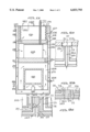
- FIG. 1A is a cross-sectional block diagram illustrating the major components of an embodiment of the present invention and the process flow through the various components
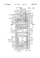
- FIG. 1B is a cross-sectional detailed view of a preferred embodiment of the present invention
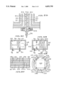
- FIGS. 2A, 2B, 2C, and 2D are cross-sectional views of injector nozzle designs useful in the present invention.
- FIGS. 3A and 3B are cross-sectional views of alternate embodiments of the reformer chamber of the present invention.
- FIG. 4A is a cross-sectional view of one embodiment of the fuel cell stack and FIG. 4B is an elevational view of the fuel cell along line IVB--IVB of FIG. 1B.
- FIG. 1A a cross-sectional block diagram illustrating the arrangement of major components of the integrated power module of the present invention, together with the flow path of the process air, the process fuel, and the product gas stream through the major components.
- the integrated power module comprises a housing 110, in which a reformer 116, a fuel cell 118 and a combustor 120 are integrated into a single insulated assembly.
- a reformer 116, a fuel cell 118 and a combustor 120 are integrated into a single insulated assembly.
- inlet air 112 enters through inlet tube 113 at one end of the housing 110, which housing may be of any desired shape, but is preferably cylindrical in shape for improved efficiency, lower cost, and simpler fabrication.
- the inlet air 112 moves along an outer, annular volume 114 which is in heat exchange relationship with a barrier in the form of one or more compression springs 124.
- the compression spring or springs 124 surround the combustor 120 and are cooled by the inlet air 112.
- the spring force of the compression spring(s) 124 is partially preserved by the cooling.
- the compression spring(s) 124 act between an end (preferably, the upper end) of the housing 110 and a compression plate set 133 and exert a mechanical force on the fuel cell 118.
- the compression plate set 133 comprises individual plates 130, 131, and 132, which are described in more detail in connection with FIG. 1B.
- the inlet air 112 traveling along the annular volume 114 also effects cooling of the fuel cell 118 through flexible barrier wall 126.
- the fuel cell 118 is positioned below the combustor 120.
- a portion of the inlet air 112 is diverted through orifice 128 to provide oxygen to the cathode manifold of the fuel cell 118.
- the orifice 128 can be positioned at any suitable position between the top and bottom of annular volume 114 and may be of any appropriate shape so as to permit introduction and distribution of inlet air 112 into the fuel cell 118 at the appropriate flow rate and inlet temperature.
- the remaining inlet air 112 which flows through the annular volume 114 and below fuel cell 118 will continuously absorb heat from (i.e., be preheated by) the product gas of reformer 116 through heat exchange wall 172.
- the inlet air 112 is preheated to at least 1000° F., and, most preferably, is heated to between 1000° F. and 1800° F. (or higher) to enhance efficiency.
- the inlet fuel 156 is supplied to the fuel injector 160 through a conduit 158 located at any suitable position on the housing 110.
- the inlet fuel may comprise any combustible fuel or fuel/steam mixture.
- the conduit 158 is inserted in annular volume 114 so that the inlet fuel 156 is preheated through contact with either heat exchange wall 172 (which is in thermal contact with reformer product gas) or the now-preheated inlet air 112, or both.
- the inlet fuel 156 is preferably preheated to between 500° F. and 1000° F.
- Other embodiments of conduit 158 are feasible, including a separate shell surrounding annular volume 114 or other means of preheating the inlet fuel 156 through contact with heat exchange wall 172 or preheated air in annular volume 114.
- the preheated inlet air 112 and inlet fuel 156 are introduced to the reformer 116 through a nozzle 169, which comprises a fuel injector 160 and an air injector 22, which are described in greater detail below.
- the inlet air 112 and the inlet fuel 156 become mixed upon injection into the reformer 116.
- nozzle designs capable of providing air/fuel intermixing will be apparent to those skilled in the art. Examples of suitable nozzle configurations are discussed in greater detail in conjunction with FIGS. 2A, 2B, 2C, and 2D.
- the fuel and the gas can be mixed prior to introduction into the reformer, such that the fuel injector and the air injector may be the same (e.g., the nozzle may comprise a single injector for both fuel and gas).
- partial oxidation combustion at a fuel-rich level i.e., air/fuel stoichiometric ratio less than about 0.8
- the air/fuel stoichiometric ratio is preferably between about 0.1 and 0.7 and most preferably is between about 0.2 and 0.4.
- the air/fuel mixture is ignited (e.g., by way of a spark plug) and, typically, reforming temperatures in the 2300-3000° F. range are achieved. Reformer product gases then pass out of the reformer 116 and into passage 168 and thereby heat the heat exchange wall 172, which is in heat exchange relationship with annular volume 114.
- the velocity of the gas in passage 168 is preferably maintained high to enhance heat transfer.
- Water and/or steam may be introduced through input 166 and injected into the reformer product gas in passage 168; input 166 may be placed at any suitable position.
- Input 166 may be in thermal contact with heat exchange wall 172 to facilitate evaporation of water in input 166 prior to injection into passage 168. The water vapor thereby quenches the temperature of the reformer product gas stream.
- the temperature of the reformer product gas is lowered to approximately 1300° F. based on fuel cell requirements and product gas stability.
- the partially-cooled reformer product gas stream flows from passage 168 into the anode manifold of the fuel cell through channel 190 located in current collector wall 31, which is positioned between the fuel cell 118 and the reformer 116.
- the fuel cell is operated under stoichiometrically-balanced conditions, so that fuel is reacted with oxygen electrochemically to yield electricity with high efficiency, without unwanted side reactions that create pollution.
- the fuel cell 118 generates direct current which may be drawn off for external use through terminals 10 and 12, which may be placed at any of various positions on the module as appropriate. The voltage and current output is dependent on the fuel cell area, number of cells, and performance.
- the anode exhaust gas exiting the fuel cell 118 passes through exit passage 134 into combustor 120 after undergoing some temperature quenching by virtue of contact with the flexible heat transfer barrier wall 126, which is in thermal contact with the relatively cooler inlet air 112.
- the temperature of the anode exhaust gas is approximately 1500° F., but is dependent on the fuel cell type and performance, and the extent of heat transfer through flexible barrier wall 126 and water injected at input 166.
- the cathode exhaust gas from the fuel cell 118 is directed to the combustor 120 through conduit 129 (shown in FIG. 4B).
- the combustor 120 is preferably operated at a fuel-lean level (i.e., air/fuel stoichiometric ratio above about 1.1; most preferably, above about 1.4).
- the combustor preferably includes a heat recovery device, such as a heat transfer coil 142, to deliver the heat energy recovered from the process and/or generated by combustion to a downstream user or appliance.
- the exhaust gas 144 from the module passes out of the system through exhaust duct 141 (shown in FIG. 1B).
- the housing 110 is thermally insulated to minimize heat loss and to provide external thermal protection for users. Any of a variety of insulating materials can be used, including but not limited to fiberboards, foams, and/or blanks which are selected for their insulation properties and temperature compatibility.
- the housing 110 also includes a cover flange 111 which optionally can be removed for direct access to the combustor 120 and compression spring(s) 124. Withdrawal of the combustor 120 and compression spring(s) 124 through the cover flange 111 permits access to and withdrawal of the fuel cell 118 and reformer 116. Accessibility to the individual components of the integrated power module is useful for maintenance, inspection, and repair of the components, if necessary.
- compression springs 124 are composed of materials which when heated expand in such a way as to increase the compressive force.
- compression spring(s) 124 provide mechanical force between the underside of the cover flange 111 and compression plate 130, the topmost plate of the compression plate set 133 (shown in FIG. 1A), which plate set comprises plates 130, 131, and 132.
- the flexible barrier wall 126 which can resemble a bellows, surrounds the fuel cell 118 and extends downward from the underside or the periphery of the compression plate set 133 to sealingly engage the current collector wall 31, located above the reformer 116.
- a ring seal or weld is used to provide a gas-tight interface seal between the lower end of the flexible barrier wall 126 and the outer periphery of compression plate 130.
- a ring seal or weld provides a gas-tight seal between current collector wall 31 and (i) flexible barrier wall 126, and (ii) heat exchange wall 172.
- the compression spring(s) 124 and the flexible barrier wall 126 permit thermal expansion and contraction of the fuel cell 118 during operation of the module.
- An electrical insulation plate 131 is positioned between compression plate 130 and current collector plate 132.
- current collector plate 132 is positive (cathode side), but the stack polarity can be reversed, if desired.
- Positive terminal 10 which is in electrical contact with current collector plate 132, provides a user connection to the electrical current produced by the fuel cell.
- the combustor 120 is provided with an exhaust duct 141 attached to the cover flange 111 to direct exhaust gas 144 out of the module.
- the exhaust duct 141 can be moved with the cover flange 111 when the cover flange 111 is removed from the housing 110.
- the bottom of exhaust duct 141 engages or interfaces with a perforated surface element 14, which serves as the base for and defines the physical dimensions of the combustor 120.
- Surface element 14 can be catalyzed to enhance spontaneous ignition or the combustion chamber 120 can be equipped with a spark ignition source (not shown).
- a removable heat transfer coil 142 located in the exhaust duct 141 is provided to recover heat for downstream or external use.
- the reformer 116 in FIG. 1B is located proximate to the bottom of the integrated power module and is insulated thermally from a bottom seal plate 300, which is supported against the base 162 at the bottom of the module assembly.
- a spark plug 174 extends into the reformer 116 through bottom seal plate 300 and the base 162 to provide ignition during start-up of the reforming combustion.
- the housing 110 may optionally be provided with valved tubes 164 and 176, which will serve to allow bleeding off of air from annular volume 114 or addition of additional air to annular volume 114. These bleed tubes will allow adjustment of the air flow which may be required to control the amount of oxygen delivered to the reformer 116, temperature of the preheated air 112, and/or the level of cooling provided to the reformer product gas and the fuel cell 118. These will be utilized to control the temperature and mass flow of the incoming air to provide the proper mixture at air injector 22. Appropriate sensors may be employed within the annular volume 114 to control air valves 178 and 179 provided in the valved tubes 176 and 164, respectively. Additionally, the housing 110 may be provided with an ancillary input 166 to supply steam or methane or a mixture of these to the passage 168. Thus, the constituents of the gas products can be optimized prior to introduction to the fuel cell 118.
- inlet process air 112 is introduced through inlet tube 113 into annular volume 114, which is created by the space between the inside wall of the housing 110 and (i) the compression spring(s) 124, (ii) the flexible barrier wall 126, and (iii) the heat exchange wall 172.
- the relatively cool inlet air 112 serves to cool the compression spring(s) 124.
- a portion of the inlet air 112 is diverted through orifice 128 to provide oxygen to the fuel cell 118.
- the diverted inlet air 112 ultimately flows through the fuel cell 118, in which oxygen from the inlet air 112 is consumed.
- the temperature of the preheated air entering orifice 128 will be approximately 1000-1300° F., but the temperature will be fuel cell type dependent.
- the placement of orifice 128 can be at any appropriate position to achieve the desired temperature.
- An extension tube down along heat exchange wall 172 can be used to effect increased temperatures.
- the diverted, now oxygen-depleted air stream exits the fuel cell 118 and enters cathode outlet manifold 238 (shown in FIG. 4B), eventually passing through conduit 129 (shown in FIG. 4B) and through insulation plate 131 and compression plate 130.
- the depleted air finally enters pre-combustion zone 16 and passes through port(s) 140 into the combustor 120.
- inlet air 112 will pass in heat exchange relationship with heat exchange wall 172 to take up heat from and thereby cool the product gases in annular volume 168.
- Inlet air 112 is preheated as a result of movement along the annular volume 114 and enters the reformer 116 through air injector 22 at a temperature of approximately 1000-1600° F., or even higher.
- inlet fuel 156 enters the module through conduit 158 and is preheated by heat exchange surfaces 159, which are in thermal contact with heat exchange wall 172.
- Preheated inlet fuel 156 is injected into reformer 116 through fuel injector 160.
- preheated inlet air 112 is injected into reformer 116 through air injector 22.
- the inlet air and fuel begin to mix upon injection into reformer 116, and are further mixed by impingement upon the rear wall 23 (top wall of reformer 116 in FIG. 1B), which faces the injectors and whose plane is transverse to the direction of the injected air and fuel.
- FIG. 1B illustrates the process flow path 42 of the air/fuel mixture within the reformer 116.
- Flow ring 170 promotes increased recirculation of the fuel/air mixture within the reformer 116 to enhance combustion and mixing.
- reformer product gases exit through passage 168 which extends the length of the reformer 116 and enters the anode manifold of the fuel cell 118 through conduit 190.
- the reformer product gases may be temperature-quenched with water, steam, methane, or other fluid or gas from input 166 prior to introduction into the fuel cell 118.
- catalyst can be disposed in passage 168 and a steam/fuel mixture can be introduced through input 166, thereby promoting an endothermic steam reforming-type reaction that achieves the desired quenching effect.
- reformer product gas carbon monoxide (CO) is converted into carbon dioxide (CO 2 ) and hydrogen (H 2 ) via a shift reaction.
- Water produced by the fuel cell 118 is vaporized and exits with the depleted fuel stream through exit passage 134 located in insulation plate 131 and compression plate 130.
- the depleted fuel then enters the fuel distribution zone 18 and enters the combustor 120 through perforated surface element 14.
- the fuel cell 118 is equipped with terminals 10 and 12. to supply current to an external device. Electrical energy from the fuel cell 118 is collected in current collector wall 31 and flows through conductive flexible barrier wall 126 into compression plate 130, where it subsequently passes into compression spring(s) 124 and into ground terminal 12 located on cover flange 111. Ground terminal 12 can be located at any other appropriate location on the housing 110 which is in electrical contact with current collector wall 31. The electrical energy then flows to a customer's load. Electrons from the customer load enter the positive terminal 10 and flow to the current collector plate 132, where they are transferred back into the fuel cell 118. Insulation layer 175 provides isolation of the positive terminal 10 from the grounded cover flange 111 and compression plate 130. Insulation plate 131 provides electrical isolation between current collector plate 132, compression plate 130, and flexible barrier wall 126.
- the anode exhaust gas from the fuel cell 118 will be passed to combustor 120 through exit passage 134 at a temperature of typically 1500° F. to 1800° F., but this again will depend on the fuel cell type, performance, and the extent of heat transfer through flexible barrier wall 126.
- the cathode exhaust gas will exit the fuel cell 118 and be passed also to combustor 120, but through a conduit 129 (shown in FIG. 4B), again at approximately the same temperature.
- depleted air from port(s) 140 and depleted fuel from perforated surface element 14 react and combust to liberate heat, which can be recovered by a downstream user or appliance through a heat transfer coil 142.
- the thermal energy recovered in this manner can be used to heat water that is then circulated through a residence or workplace to provide either hot water or heat, as needed.
- exhaust gas 144 exits the integrated power module through exhaust duct 141.
- the module is a liquid-fueled system
- steam or a small amount of air may be introduced via tube 157 so that it becomes premixed with the inlet fuel 156, thereby enhancing the reforming process and preventing particulate formation within the reformer 116.
- additional heat can be generated by enhancing combustion within the combustor 120 by adding air through conduit 138 to mix with the depleted air from conduit 129, and/or adding fuel through conduit 136 to mix with the depleted air from exit passage 134.
- increased control over characteristics such as the preheating temperature, process cooling, humidity and process stoichiometric composition/ratios can be achieved through various features or modifications.
- features or modifications include: (i) passing additional air through inlet port 113 and/or withdrawing a portion of the inlet air 112 through air valve 178 and/or air valve 179 to enhance the cooling effect on the fuel cell 118 (this procedure also results in better control of the preheating temperatures for air entering the fuel cell through orifice 128); (ii) passing additional air into the module through air valve 178 to enhance the cooling effect of reformer product gases exiting in passage 168 or to better control the preheating temperature of the air entering the reformer 116; (iii) adding or removing air via air valve 179 to better control the preheating temperature of reformer air and the reformer stoichiometric ratios; and (iv) withdrawing air from air valves 178 and 179 and reinjecting the air into the module through conduit 138 to enhance heat recovery
- the performance of the integrated power module may be optimized by controlling one or more parameters by directing through the one or more valves, conduits, or inlets at least one process enhancer such as but not limited to an oxygen-containing gas, a combustible fuel, water (or steam), carbon dioxide, or air.
- the parameters which can be controlled include the inlet gas, the inlet fuel, the injected fuel, the injected gas, the reformer product gas, the fuel cell inlet gas, the anode exhaust gas, the cathode exhaust gas, the combustor inlet gas, and the combustor exhaust gas.
- the reformer port 20 at the entrance to the reformer 116 is defined by flow ring 170, which may preferably have a thickness of from one-half to three inches in the direction of flow from the end of the injectors 160 and 22.
- the fuel injector 160 comprises the inner volume of the coaxial nozzle
- the air injector 22 comprises the outer annular volume of the coaxial nozzle.
- the inlet fuel may comprise any suitable liquid or gaseous fuel, including but not limited to natural gas, ethanol, methanol, gasoline, kerosene, methane, and mixtures thereof with steam.
- the two injectors 22 and 160 are preferably coterminous at nozzle end 27. With such an arrangement, the flow from nozzle end 27 will collapse on itself and enhance inlet air/fuel mixing prior to combustion.
- the nozzle end 27 of the fuel injector 160 and the air injector 22 is preferably located in a plane that is coplanar or lower relative to the reformer port 20 as shown in FIG. 2A. The positioning of the nozzle end 27 may be adjusted to achieve different reaction characteristics, if desired.
- the flow of reformer product gases is indicated by arrows.
- the reformer port 20 defined by flow ring 170 is of sufficient size to permit unimpeded injection of the fuel and air.
- the nozzle is constructed from concentric tubes 23 and 24, together with a central rod 25.
- air is fed through air injector 22, while fuel is fed through fuel injector 160; however, alternate combinations are feasible.
- the presence of the central rod 25 will enhance the gas mixing at the nozzle end 27.
- the central rod 25 is replaced by a plug 25, provided with a fuel passage 33 centrally therein.
- a deflector 29 is located in line with the axis of the fuel passage 33 and defines diverging fuel outlets 37.
- the deflector 29 can be supported by struts (not shown) extending across the fuel outlets 37.
- a steam/fuel mixture is preferably supplied through injector 161 and air through air injector 22, although these supplies can be interchanged.
- This configuration with deflector 29 and with the appropriate dimensioning of the diameters of the tubes 23 and 24, and with the appropriate pressure for the steam, creates a suction on the inlet fuel passage as the steam flows past fuel outlets 37, thereby enhancing mixing and promoting vaporization at the exit end of the nozzle.
- Deflector 29 can also be constructed from a capped tube with holes providing fuel outlet 37. Holes can also be added in tube 24 to allow air and fuel premixing prior to injection into reformer 116.
- the central rod 25 is made of a tube 400 surrounding a spark igniter 402, which replaces spark plug 174 of FIG. 1B.
- Spark igniter 402 is made from a conductive rod 404 and a non-conductive insulation sleeve 406. Seal ring 408 is used as a pressure seal.
- FIG. 3A there is shown an alternate embodiment of a reactor chamber 54, the interior 56 of which serves as a combustion zone and which is provided with a helical tube 62 which receives a fuel gas through an inlet 58 and an oxygen-containing gas through an inlet 60.
- the fuel and oxygen-containing gases are heated during their passage through the helical tube 62 to provide an intimate mixture, which is then injected into the chamber 56 through outlet 64.
- the gases are further mixed by directly impinging on the rear wall 66 as shown.
- a sparking device 74 is provided to initiate ignition.
- the reaction products will then in turn heat the contents of the helical tube 62 before exiting through the outlet 68.
- FIG. 3A a modification of the arrangement of FIG. 3A is shown where the fuel and air flows are maintained separate as heating of both flows takes place in separate helical tubes 62a and 62b .
- a flow ring 70 is positioned approximately coplanar with outlet 64 to enhance recirculation of the air/fuel mixture within the reformer.
- the functional heat exchange walls 172 and 159 in FIG. 1B are replaced by the walls of components 58, 60, 62, 62a, and 62b.
- the function of conduit 190 in FIG. 1B is replaced by outlet 68.
- the structures of the present invention are not limited in their applications by the scale of the parts although there may be a practical commercial upper limit for the fuel cells.
- FIGS. 4A and 4B there are shown schematically two views of a fuel cell stack that can be usefully employed with the present invention. It will be understood, of course, that other electrochemical converters can also be employed so long as these devices are capable of making use of the hydrogen generated by reformer 116.
- FIGS. 4A and 4B While stacked rectangular plates are illustrated in FIGS. 4A and 4B, with external manifold areas defined by the intersection of the stacked corners with the inside surface of the flexible barrier wall 126, it will be readily appreciated by those skilled in this technology that circular planar cells with internal manifolds or tubular arrays of cells could be fully employed with modifications to the placement of interface passages 190, 134, 128 and 129. In the illustrated form, corner seals 127 are required to separate the gas flows through the cell.
- a cathode plate series 180 and cathode gas passage 180a is interleaved with anode plate series 182 and anode gas passage 182a, with the anode plates and cathode plates separated by suitable electrolytic layers 184 and a separator plate 302. Due to the elevated temperature of the reaction gases, and the high hydrogen content on the anode plates and high oxygen content on the cathode plates, the following reactions will take place with a solid oxide fuel cell: ##EQU1##
- the electrolyte which is ion uses an electrolyte which is preferably a solid oxide or a molten carbonate, but other electrolyte layers are feasible that are electrically conducting and/or conduct positive or negative ions (i.e., are ionically conducting).
- electrolyte which is preferably a solid oxide or a molten carbonate, but other electrolyte layers are feasible that are electrically conducting and/or conduct positive or negative ions (i.e., are ionically conducting).
- fuel cells operate at a temperature of 1000° to 1800° F. (600-1000° C.). At these operating temperatures, water that is generated will be quickly evaporated and moved with the gas flowing out of the fuel cell.
- Any suitable porous metal oxides, conductive ceramics, or metal can, of course, be employed as the electrodes.
- the fuel cell exhaust anode and cathode gases can be fed to the combustor 120 and combusted.
- combustion will occur with low emissions, in particular, low thermal NO x .
- Steam may be provided in the reformer product gas flow to the anodes of the fuel cell stack to facilitate the reactions producing carbon dioxide, hydrogen and heat. This will eliminate carbon monoxide in the fuel cell anode passages and thereby minimize objectionable pollutants.
- the anode off-gases will pass through exit passage 134 and can be mixed with additional methane or natural gas fuel through conduit 136 before being fed to the combustor 120. This is useful particularly at start-up to be supplied through heat transfer coil 142 or when additional heat is needed by the user. Additional air can be supplied through conduit 138 and port(s) 140 to assist in complete combustion.
- the cathode off-gases are fed through a cathode outlet manifold 238 (as shown in FIG. 4B), located in compression plate 130, into prechamber 16 and then to combustor 120.
- the current collector plate 132 will be connected on one face thereof to a terminal 10 which is insulated by a ceramic collar 175, which extends through the cover flange 111. Above the current collector plate 132 is a ceramic insulation plate 131 which includes the anode off-gas exit passage 134. A compression plate 130 is set atop insulation plate 131.
- the fuel cell 118 is preferably surrounded by a conductive stainless steel flexible barrier wall 126, which is impervious to air or gases and which is yieldable to accommodate expansion and contraction of the fuel cell 118 during operation of the module. Electrical isolation is achieved between flexible barrier wall 126 and the fuel cell plates by the corner seals 127.
- the flexible barrier wall 126 will be provided with the oppositely-located orifice 128 (to receive incoming air from the air inlet 112) and conduit 129 (to allow exhaust of cathode off-gases from within the fuel cell).
- reaction gas products from the partial oxidation reformer can also be employed in connection with a shift reactor to modify the gas products for discharge to the atmosphere or for other reactions.
- a shift reactor may be substituted for the fuel cell stack 118.
- a shift reactor/hydrogen purification electrochemical reaction device replaces the fuel cell 118.
- the overall function of the system is to generate and purify hydrogen gas for use external to the system.
- orifice 128 is connected to input 166 which provides steam to the cathode gas passages 180a (see FIG. 4A).
- the steam pressure in the cathode gas passages 180a is maintained greater than the process gas pressure in anode gas passages 182a to promote any cross-leakage to be steam and/or hydrogen from passages 180a back into anode gas passages 182a, and not the other direction.
- Orifice 128 is not connected to inlet air 112.
- the fuel cell hardware is operated as a hydrogen concentrator, which may require modifying the materials of construction of the cathode plates 180. Such modification would be apparent to one skilled in the art.
- Current from an external source or power supply is used to force electron flow through the electrochemical device. For example, the following reaction takes place with a solid oxide electrolyte cell: ##EQU2##
- cathode outlet manifold 238 is connected to conduit 129, but conduit 129 is not connected to combustion prechamber 16.
- Conduit 129 is connected to the outside of housing 110 to provide purified and humidified hydrogen to some other use or appliance.
- air is provided through conduit 138 to combustor 120 downstream of the electrochemical reaction device to facilitate combustion of any remaining hydrogen or carbon monoxide that exhausts the shift reactor/purification electrochemical device through passage 134.
- a small amount of inlet air 112 can be combined with steam from input 166 prior to entering orifice 128.
- This mixture passes into cathode gas passages 180a, where the oxygen reacts on the cathode surfaces generating potentials that drive the hydrogen concentration process discussed above.
- the external electrical connections are used to extract or supplement energy needed by the electrochemical device.
- the device 118 is constructed of metal and/or ceramic diffusion membranes that are porous to hydrogen but not to other gases in the mixed gas stream, such as nitrogen, carbon dioxide, and carbon monoxide, among others.
- These diffusion membranes consist of two sides (i.e., a mixed gas side and a purified product gas side), and can be supported or unsupported by porous ceramic structures. Because the diffusion membrane is porous to hydrogen gas, but not the other components of the mixed gas stream, only hydrogen gas is able to diffuse through the membrane from the mixed gas side to the purified product gas side.
- the membranes would replace electrolytic layers 184 and separator plate 302 of the fuel cell, and cathode plates 180 and anode plates 182 would be eliminated.
- a surface coating can be added to the membrane surface in anode gas passage 182a.
- the partial pressure of the hydrogen gas in the mixed gas stream in the anode gas passage 182a drives the movement of hydrogen through the membrane and into the cathode gas passage 180a.
- Purified hydrogen flows through conduit 129 and out of the housing 110.
- Steam from input 166 flows through orifice 128 and into cathode gas passage 180a.
- the pressure of the steam in the cathode gas passage 180a is maintained greater than the pressure of the mixed gas stream in anode gas passage 182a. This steam has two critical functions.
- the first function is to ensure any cross-leakage that may occur is from cathode gas passage 180a into anode gas passage 182a, thereby maintaining product gas purity in passage 180a.
- the second function is to decrease the hydrogen partial pressure in cathode gas passage 180a with water vapor that is easily separated and removed downstream by use of a condenser. With counter-flow directions of the mixed gas stream in anode gas passage 182a and steam/purified hydrogen in cathode gas passage 180a, a positive hydrogen partial pressure driving force can be maintained even with extremely high recovery factors (for example, most if not all the hydrogen is moved from the mixed gas stream in anode gas passage 182a to the purified hydrogen stream in cathode gas passage 180a).
- the present invention provides several embodiments that have a wide range of applications, as scaling of the configurations can be readily accomplished by those skilled in the art to provide the necessary heat, electrical energy, and/or purified hydrogen output for a particular application.
- Various modifications and equivalent substitutes may be incorporated into the invention as described above without varying from the spirit of the invention, as will also be apparent to those skilled in this technology.
- the term "air” is used herein, for convenience sake, to refer to any oxygen-containing gas suitable for use in the integrated power module.
- the Examples presented herein are intended for illustration purposes only and are not intended to act as a limitation on the scope of the following claims.
Landscapes
- Engineering & Computer Science (AREA)
- Chemical & Material Sciences (AREA)
- Chemical Kinetics & Catalysis (AREA)
- Sustainable Development (AREA)
- Sustainable Energy (AREA)
- Manufacturing & Machinery (AREA)
- Life Sciences & Earth Sciences (AREA)
- Electrochemistry (AREA)
- General Chemical & Material Sciences (AREA)
- Combustion & Propulsion (AREA)
- Mechanical Engineering (AREA)
- General Engineering & Computer Science (AREA)
- Fuel Cell (AREA)
- Hydrogen, Water And Hydrids (AREA)
- Ignition Installations For Internal Combustion Engines (AREA)
Priority Applications (10)
| Application Number | Priority Date | Filing Date | Title |
|---|---|---|---|
| US09/032,625 US6033793A (en) | 1996-11-01 | 1998-02-27 | Integrated power module |
| KR1020007009492A KR20010041370A (ko) | 1998-02-27 | 1999-02-25 | 통합형 파워 모듈 |
| EP99936142A EP1060533A1 (fr) | 1998-02-27 | 1999-02-25 | Module d'alimentation integre |
| CA002320761A CA2320761A1 (fr) | 1998-02-27 | 1999-02-25 | Module d'alimentation integre |
| AU33114/99A AU3311499A (en) | 1998-02-27 | 1999-02-25 | Integrated power module |
| PCT/US1999/004123 WO1999044252A1 (fr) | 1998-02-27 | 1999-02-25 | Module d'alimentation integre |
| JP2000533917A JP2002505510A (ja) | 1998-02-27 | 1999-02-25 | 一体化された動力モジュール |
| CN99803388A CN1292157A (zh) | 1998-02-27 | 1999-02-25 | 集成能源组件 |
| IL13809699A IL138096A0 (en) | 1998-02-27 | 1999-02-25 | Integrated power module |
| US09/804,601 US20020006535A1 (en) | 1996-11-01 | 2001-03-12 | Integrated power module |
Applications Claiming Priority (2)
| Application Number | Priority Date | Filing Date | Title |
|---|---|---|---|
| US08/742,383 US5944510A (en) | 1996-11-01 | 1996-11-01 | Dynamic fluid injector |
| US09/032,625 US6033793A (en) | 1996-11-01 | 1998-02-27 | Integrated power module |
Related Parent Applications (1)
| Application Number | Title | Priority Date | Filing Date |
|---|---|---|---|
| US08/742,383 Continuation-In-Part US5944510A (en) | 1996-11-01 | 1996-11-01 | Dynamic fluid injector |
Related Child Applications (1)
| Application Number | Title | Priority Date | Filing Date |
|---|---|---|---|
| US51272700A Continuation | 1996-11-01 | 2000-02-24 |
Publications (1)
| Publication Number | Publication Date |
|---|---|
| US6033793A true US6033793A (en) | 2000-03-07 |
Family
ID=21865936
Family Applications (1)
| Application Number | Title | Priority Date | Filing Date |
|---|---|---|---|
| US09/032,625 Expired - Fee Related US6033793A (en) | 1996-11-01 | 1998-02-27 | Integrated power module |
Country Status (9)
| Country | Link |
|---|---|
| US (1) | US6033793A (fr) |
| EP (1) | EP1060533A1 (fr) |
| JP (1) | JP2002505510A (fr) |
| KR (1) | KR20010041370A (fr) |
| CN (1) | CN1292157A (fr) |
| AU (1) | AU3311499A (fr) |
| CA (1) | CA2320761A1 (fr) |
| IL (1) | IL138096A0 (fr) |
| WO (1) | WO1999044252A1 (fr) |
Cited By (43)
| Publication number | Priority date | Publication date | Assignee | Title |
|---|---|---|---|---|
| US6350394B1 (en) | 1996-12-23 | 2002-02-26 | Egt Developments, Llc | Method and apparatus for total energy fuel conversion systems |
| US20020051898A1 (en) * | 2000-09-28 | 2002-05-02 | Moulthrop Lawrence C. | Regenerative electrochemical cell system and method for use thereof |
| WO2002045838A1 (fr) * | 2000-12-05 | 2002-06-13 | Texaco Development Corporation | Processeur de combustible compact pour production de gaz riche en hydrogene |
| EP1231659A2 (fr) * | 2001-02-13 | 2002-08-14 | Delphi Technologies, Inc. | Méthode et dispositif pour contrôler la température dans les zones différentes d'une unité de puissance auxiliaire de piles à combustible à oxydes solides |
| US6436561B1 (en) * | 1999-07-21 | 2002-08-20 | General Motors Corporation | Methanol tailgas combustor control method |
| US6440594B1 (en) * | 1999-06-17 | 2002-08-27 | California Institute Of Technology | Aerosol feed direct methanol fuel cell |
| US20020172846A1 (en) * | 2001-05-09 | 2002-11-21 | Hagan Mark R. | Cogeneration of power and heat by an integrated fuel cell power system |
| US6531238B1 (en) | 2000-09-26 | 2003-03-11 | Reliant Energy Power Systems, Inc. | Mass transport for ternary reaction optimization in a proton exchange membrane fuel cell assembly and stack assembly |
| WO2003022417A2 (fr) * | 2001-06-27 | 2003-03-20 | Nu Element, Inc. | Architecture de microreacteur modulaire et procede destine a des dispositifs de traitement de fluide |
| US20030138688A1 (en) * | 2001-12-27 | 2003-07-24 | Nobuki Hattori | Fuel cell power generation system |
| US6641948B1 (en) | 1999-11-17 | 2003-11-04 | Neah Power Systems Inc | Fuel cells having silicon substrates and/or sol-gel derived support structures |
| US20030234123A1 (en) * | 2002-06-24 | 2003-12-25 | Schumann David R. | Solid-oxide fuel cell system having a fuel combustor to pre-heat reformer on start-up |
| US20040048120A1 (en) * | 2000-05-01 | 2004-03-11 | Haltiner Karl Jacob | Temperature zones in a solid oxide fuel cell auxiliary power unit |
| US20040081868A1 (en) * | 2002-10-23 | 2004-04-29 | Edlund David J. | Distributed fuel cell network |
| US6739289B2 (en) | 2002-04-26 | 2004-05-25 | Caterpillar Inc | Method and apparatus for providing a hydrogen enriched fuel to combustion prechamber |
| US20040166397A1 (en) * | 2002-11-08 | 2004-08-26 | Valdez Thomas I. | Cathode structure for direct methanol fuel cell |
| US20040175665A1 (en) * | 2001-03-30 | 2004-09-09 | Goebel Steven G. | Apparatus for mixing fuel and an oxidant |
| US20040234834A1 (en) * | 2002-11-25 | 2004-11-25 | Narayanan Sekharipuram R. | Water free proton conducting membranes based on poly-4-vinylpyridinebisulfate for fuel cells |
| US20050132650A1 (en) * | 2000-06-27 | 2005-06-23 | Delphi Technologies, Inc. | Fast light-off catalytic reformer |
| US20050227129A1 (en) * | 2002-04-09 | 2005-10-13 | Masatoshi Iio | Fuel cell power plant warm up |
| EP1614964A2 (fr) | 2004-07-09 | 2006-01-11 | J. Eberspächer GmbH Co. KG | Brûleur |
| US20060051261A1 (en) * | 2002-12-31 | 2006-03-09 | Xiaoyang Rong | Fuel conversion reactor |
| US20060147771A1 (en) * | 2005-01-04 | 2006-07-06 | Ion America Corporation | Fuel cell system with independent reformer temperature control |
| US20060199060A1 (en) * | 2005-03-04 | 2006-09-07 | Michio Horiuchi | Power generating system using fuel cell |
| US20060228290A1 (en) * | 2005-04-06 | 2006-10-12 | Cabot Corporation | Method to produce hydrogen or synthesis gas |
| KR100700184B1 (ko) * | 2000-12-29 | 2007-03-27 | 주식회사 엘지이아이 | 연료전지를 이용한 세탁기 |
| GB2436396A (en) * | 2006-03-24 | 2007-09-26 | Ceres Power Ltd | Fuel Cells Stack System Assembly |
| US20080008917A1 (en) * | 2004-12-22 | 2008-01-10 | Hiroki Homma | Fuel Cell System |
| WO2008016216A1 (fr) * | 2006-08-02 | 2008-02-07 | Fuelcell Power, Inc. | Système de pile à combustible et procédé de commande de refroidissement associé |
| US20080180918A1 (en) * | 2007-01-25 | 2008-07-31 | Bruce Edwin Baker | Apparatus for positioning electronic component modules within an equipment chassis |
| WO2008110292A1 (fr) * | 2007-03-12 | 2008-09-18 | Mtu Onsite Energy Gmbh | Dispositif d'étanchéité pour un agencement de piles à combustible |
| US20090035617A1 (en) * | 2004-02-19 | 2009-02-05 | Toyota Jidosha Kabushiki Kaisha | Fuel cell system and method for controlling the same |
| US20090197141A1 (en) * | 2006-10-17 | 2009-08-06 | Canon Kabushiki Kaisha | Exhaust fuel diluting mechanism and fuel cell system with the exhaust fuel diluting mechanism |
| US20090214905A1 (en) * | 2007-01-08 | 2009-08-27 | California Institute Of Technology | Direct methanol fuel cell operable with neat methanol |
| US20110008700A1 (en) * | 2009-07-08 | 2011-01-13 | Fuelcell Energy, Inc. | Fluid diverter for a fuel cell system |
| WO2015073790A1 (fr) * | 2013-11-15 | 2015-05-21 | Delphi Technologies, Inc. | Élément chauffant ayant un assemblage pile à combustible et une chambre de combustion, et procédé de fonctionnement |
| US20150140461A1 (en) * | 2013-11-15 | 2015-05-21 | Delphi Technologies, Inc. | Method of operating a heater |
| US9627700B2 (en) | 2013-11-06 | 2017-04-18 | Watt Fuel Cell Corp. | Liquid fuel CPOX reformer and fuel cell systems, and methods of producing electricity |
| US9624104B2 (en) | 2013-11-06 | 2017-04-18 | Watt Fuel Cell Corp. | Liquid fuel CPOX reformers and methods of CPOX reforming |
| US9627699B2 (en) | 2013-11-06 | 2017-04-18 | Watt Fuel Cell Corp. | Gaseous fuel CPOX reformers and methods of CPOX reforming |
| US9627701B2 (en) | 2013-11-06 | 2017-04-18 | Watt Fuel Cell Corp. | Integrated gaseous fuel CPOX reformer and fuel cell systems, and methods of producing electricity |
| US10106406B2 (en) | 2013-11-06 | 2018-10-23 | Watt Fuel Cell Corp. | Chemical reactor with manifold for management of a flow of gaseous reaction medium thereto |
| US10676354B2 (en) | 2013-11-06 | 2020-06-09 | Watt Fuel Cell Corp. | Reformer with perovskite as structural component thereof |
Families Citing this family (27)
| Publication number | Priority date | Publication date | Assignee | Title |
|---|---|---|---|---|
| EP0977295A1 (fr) * | 1998-07-31 | 2000-02-02 | Sulzer Hexis AG | Installation de piles à combustible fonctionnant à haute température |
| US5985474A (en) * | 1998-08-26 | 1999-11-16 | Plug Power, L.L.C. | Integrated full processor, furnace, and fuel cell system for providing heat and electrical power to a building |
| DE19930872A1 (de) * | 1999-07-05 | 2001-01-18 | Siemens Ag | Brennstoffzellenanlage mit integrierter Gasreinigung und Verfahren zur Reinigung des Reformergases |
| US6329091B1 (en) | 2000-04-14 | 2001-12-11 | Ford Global Technologies, Inc. | Fuel reformer system for a fuel cell |
| EP1231658A3 (fr) * | 2001-02-13 | 2007-11-07 | Delphi Technologies, Inc. | Dispositif de combustion dans une intallation de pile à combustible pour la récupération d'énergie perdue |
| JP4322107B2 (ja) | 2003-12-17 | 2009-08-26 | 本田技研工業株式会社 | 燃料電池システム |
| KR100599685B1 (ko) * | 2004-06-30 | 2006-07-13 | 삼성에스디아이 주식회사 | 연료 전지 시스템의 개질기 및 이를 채용한 연료 전지시스템 |
| KR100853977B1 (ko) | 2004-12-22 | 2008-08-25 | 혼다 기켄 고교 가부시키가이샤 | 연료 전지 시스템 |
| JP4654021B2 (ja) | 2004-12-22 | 2011-03-16 | 本田技研工業株式会社 | 多管式熱交換装置及びその製造方法 |
| JP4598508B2 (ja) * | 2004-12-22 | 2010-12-15 | 本田技研工業株式会社 | 燃料電池システム |
| CN101207210B (zh) * | 2006-12-21 | 2010-04-21 | 大同股份有限公司 | 低启动电力的燃料电池系统 |
| JP5219441B2 (ja) * | 2007-09-13 | 2013-06-26 | Jx日鉱日石エネルギー株式会社 | 燃料電池システム |
| JP5231897B2 (ja) * | 2008-08-22 | 2013-07-10 | トヨタ自動車株式会社 | 燃料電池モジュール |
| JP5645375B2 (ja) * | 2009-07-17 | 2014-12-24 | 三菱重工業株式会社 | コンバインド発電システム |
| ITCO20100037A1 (it) * | 2010-07-26 | 2012-01-26 | Giacomini Spa | "sistema di produzione di energia da idrogeno, in particolare per abitazioni" |
| JP2011029201A (ja) * | 2010-10-04 | 2011-02-10 | Kyocera Corp | 燃料電池及び燃料電池の運転方法 |
| US9119946B2 (en) * | 2013-01-23 | 2015-09-01 | Carefusion 2200, Inc. | Antiseptic applicator |
| AT513913B1 (de) * | 2013-02-04 | 2016-12-15 | Avl List Gmbh | Brennstoffzellensystem, welches mit Kohlenwasserstoffen betreibbar ist |
| AT15137U1 (de) * | 2013-02-04 | 2017-01-15 | Avl List Gmbh | Brennstoffzellensystem, welches mit Kohlenwasserstoffen betreibbar ist |
| AT513912B1 (de) | 2013-02-04 | 2016-08-15 | Avl List Gmbh | Energieerzeugungseinheit mit einem Hochtemperatur-Brennstoffzellenstack und einer Verdampfungseinheit |
| WO2014155928A1 (fr) | 2013-03-25 | 2014-10-02 | 住友精密工業株式会社 | Pile à combustible |
| GB2536905B (en) | 2015-03-30 | 2020-01-08 | Edwards Ltd | Radiant burner |
| JP6470639B2 (ja) * | 2015-06-10 | 2019-02-13 | 東京瓦斯株式会社 | 燃料電池モジュール |
| JP6893308B2 (ja) * | 2016-04-26 | 2021-06-23 | パナソニックIpマネジメント株式会社 | 燃料電池装置 |
| KR102155641B1 (ko) * | 2017-09-14 | 2020-09-15 | 블룸 에너지 코퍼레이션 | 스파크 이그나이터를 사용한 고체 산화물 연료 전지 시스템 기동을 위한 내부 광 오프 메커니즘 |
| CN112349926A (zh) * | 2020-09-29 | 2021-02-09 | 中国电子科技集团公司第十八研究所 | 一种可快速启动的车载燃料电池系统 |
| CN113193211B (zh) * | 2021-04-20 | 2023-02-10 | 内蒙古民族大学 | 一种氢能装置内置燃烧供热结构 |
Citations (15)
| Publication number | Priority date | Publication date | Assignee | Title |
|---|---|---|---|---|
| US3207953A (en) * | 1962-11-07 | 1965-09-21 | Hunter | Incandescent ceramic electrical igniter |
| CA842127A (en) * | 1970-05-19 | Von Wiesenthal Peter | Process and apparatus for high-temperature conversions | |
| US3616334A (en) * | 1968-07-05 | 1971-10-26 | Gen Electric | Electrically and chemically coupled power generator and hydrogen generator |
| US4374184A (en) * | 1981-09-29 | 1983-02-15 | Westinghouse Electric Corp. | Fuel cell generator and method of operating same |
| US4729931A (en) * | 1986-11-03 | 1988-03-08 | Westinghouse Electric Corp. | Reforming of fuel inside fuel cell generator |
| US4983471A (en) * | 1989-12-28 | 1991-01-08 | Westinghouse Electric Corp. | Electrochemical cell apparatus having axially distributed entry of a fuel-spent fuel mixture transverse to the cell lengths |
| US5047299A (en) * | 1990-07-25 | 1991-09-10 | Westinghouse Electric Corp. | Electrochemical cell apparatus having an integrated reformer-mixer nozzle-mixer diffuser |
| US5143800A (en) * | 1990-07-25 | 1992-09-01 | Westinghouse Electric Corp. | Electrochemical cell apparatus having combusted exhaust gas heat exchange and valving to control the reformable feed fuel composition |
| US5207185A (en) * | 1992-03-27 | 1993-05-04 | Leonard Greiner | Emissions reduction system for internal combustion engines |
| US5299536A (en) * | 1992-03-27 | 1994-04-05 | David Moard | Apparatus and method for decreasing nitrogen oxide emissions from internal combustion power sources |
| US5437123A (en) * | 1993-11-08 | 1995-08-01 | Hydrogen Burner Techn Inc | Underoxidized burner utilizing improved injectors |
| US5498487A (en) * | 1994-08-11 | 1996-03-12 | Westinghouse Electric Corporation | Oxygen sensor for monitoring gas mixtures containing hydrocarbons |
| US5546701A (en) * | 1994-09-20 | 1996-08-20 | Hydrogen Burner Technology, Inc. | Underoxidized burner utilizing improved injectors |
| US5664943A (en) * | 1994-07-13 | 1997-09-09 | Abb Research Ltd. | Method and device for operating a combined burner for liquid and gaseous fuels |
| US5711882A (en) * | 1995-09-29 | 1998-01-27 | Membrane Technology And Research, Inc. | Gas separation membrane module and process |
Family Cites Families (1)
| Publication number | Priority date | Publication date | Assignee | Title |
|---|---|---|---|---|
| US3516807A (en) * | 1966-04-06 | 1970-06-23 | Texas Instruments Inc | Apparatus for producing hydrogen gas by the partial oxidation of a carbonaceous fuel containing hydrogen |
-
1998
- 1998-02-27 US US09/032,625 patent/US6033793A/en not_active Expired - Fee Related
-
1999
- 1999-02-25 KR KR1020007009492A patent/KR20010041370A/ko not_active Application Discontinuation
- 1999-02-25 AU AU33114/99A patent/AU3311499A/en not_active Abandoned
- 1999-02-25 IL IL13809699A patent/IL138096A0/xx unknown
- 1999-02-25 CA CA002320761A patent/CA2320761A1/fr not_active Abandoned
- 1999-02-25 JP JP2000533917A patent/JP2002505510A/ja not_active Withdrawn
- 1999-02-25 EP EP99936142A patent/EP1060533A1/fr not_active Withdrawn
- 1999-02-25 CN CN99803388A patent/CN1292157A/zh active Pending
- 1999-02-25 WO PCT/US1999/004123 patent/WO1999044252A1/fr not_active Application Discontinuation
Patent Citations (17)
| Publication number | Priority date | Publication date | Assignee | Title |
|---|---|---|---|---|
| CA842127A (en) * | 1970-05-19 | Von Wiesenthal Peter | Process and apparatus for high-temperature conversions | |
| US3207953A (en) * | 1962-11-07 | 1965-09-21 | Hunter | Incandescent ceramic electrical igniter |
| US3616334A (en) * | 1968-07-05 | 1971-10-26 | Gen Electric | Electrically and chemically coupled power generator and hydrogen generator |
| US4374184A (en) * | 1981-09-29 | 1983-02-15 | Westinghouse Electric Corp. | Fuel cell generator and method of operating same |
| US4729931A (en) * | 1986-11-03 | 1988-03-08 | Westinghouse Electric Corp. | Reforming of fuel inside fuel cell generator |
| US4983471A (en) * | 1989-12-28 | 1991-01-08 | Westinghouse Electric Corp. | Electrochemical cell apparatus having axially distributed entry of a fuel-spent fuel mixture transverse to the cell lengths |
| US5047299A (en) * | 1990-07-25 | 1991-09-10 | Westinghouse Electric Corp. | Electrochemical cell apparatus having an integrated reformer-mixer nozzle-mixer diffuser |
| US5143800A (en) * | 1990-07-25 | 1992-09-01 | Westinghouse Electric Corp. | Electrochemical cell apparatus having combusted exhaust gas heat exchange and valving to control the reformable feed fuel composition |
| US5207185A (en) * | 1992-03-27 | 1993-05-04 | Leonard Greiner | Emissions reduction system for internal combustion engines |
| US5299536A (en) * | 1992-03-27 | 1994-04-05 | David Moard | Apparatus and method for decreasing nitrogen oxide emissions from internal combustion power sources |
| US5437123A (en) * | 1993-11-08 | 1995-08-01 | Hydrogen Burner Techn Inc | Underoxidized burner utilizing improved injectors |
| US5441546A (en) * | 1993-11-08 | 1995-08-15 | Moard; David | Apparatus and method for decreasing nitrogen oxide emissions from internal combustion power sources |
| US5529484A (en) * | 1993-11-08 | 1996-06-25 | Moard; David M. | Apparatus and method for decreasing nitrogen oxide emissions from internal combustion power sources |
| US5664943A (en) * | 1994-07-13 | 1997-09-09 | Abb Research Ltd. | Method and device for operating a combined burner for liquid and gaseous fuels |
| US5498487A (en) * | 1994-08-11 | 1996-03-12 | Westinghouse Electric Corporation | Oxygen sensor for monitoring gas mixtures containing hydrocarbons |
| US5546701A (en) * | 1994-09-20 | 1996-08-20 | Hydrogen Burner Technology, Inc. | Underoxidized burner utilizing improved injectors |
| US5711882A (en) * | 1995-09-29 | 1998-01-27 | Membrane Technology And Research, Inc. | Gas separation membrane module and process |
Cited By (94)
| Publication number | Priority date | Publication date | Assignee | Title |
|---|---|---|---|---|
| US6734331B2 (en) | 1996-12-23 | 2004-05-11 | Egt Developments, Llc | Process for producing olefins and diolefins |
| US6350394B1 (en) | 1996-12-23 | 2002-02-26 | Egt Developments, Llc | Method and apparatus for total energy fuel conversion systems |
| US6440594B1 (en) * | 1999-06-17 | 2002-08-27 | California Institute Of Technology | Aerosol feed direct methanol fuel cell |
| US6436561B1 (en) * | 1999-07-21 | 2002-08-20 | General Motors Corporation | Methanol tailgas combustor control method |
| US6641948B1 (en) | 1999-11-17 | 2003-11-04 | Neah Power Systems Inc | Fuel cells having silicon substrates and/or sol-gel derived support structures |
| US20040048120A1 (en) * | 2000-05-01 | 2004-03-11 | Haltiner Karl Jacob | Temperature zones in a solid oxide fuel cell auxiliary power unit |
| US7037613B2 (en) | 2000-05-01 | 2006-05-02 | Delphi Technologies, Inc. | Temperature zones in a solid oxide fuel cell auxiliary power unit |
| US20060127713A1 (en) * | 2000-05-01 | 2006-06-15 | Delphi Technologies, Inc. | Temperature zones in a solid oxide fuel cell auxiliary power unit |
| US20070269694A1 (en) * | 2000-05-01 | 2007-11-22 | Delphi Technologies, Inc. | Temperature zones in a solid oxide fuel cell auxiliary power unit |
| US7279243B2 (en) | 2000-05-01 | 2007-10-09 | Delphi Technologies, Inc. | Temperature zones in a solid oxide fuel cell auxiliary power unit |
| US20050132650A1 (en) * | 2000-06-27 | 2005-06-23 | Delphi Technologies, Inc. | Fast light-off catalytic reformer |
| US6531238B1 (en) | 2000-09-26 | 2003-03-11 | Reliant Energy Power Systems, Inc. | Mass transport for ternary reaction optimization in a proton exchange membrane fuel cell assembly and stack assembly |
| US6582842B1 (en) | 2000-09-26 | 2003-06-24 | Reliant Energy Power Systems, Inc. | Enhancement of proton exchange membrane fuel cell system by use of radial placement and integrated structural support system |
| US6887601B2 (en) | 2000-09-28 | 2005-05-03 | Proton Energy Systems, Inc. | Regenerative electrochemical cell system and method for use thereof |
| US20050129996A1 (en) * | 2000-09-28 | 2005-06-16 | Moulthrop Lawrence C.Jr. | Regenerative electrochemical cell system and method for use thereof |
| US7241522B2 (en) | 2000-09-28 | 2007-07-10 | Proton Energy Systems, Inc. | Regenerative electrochemical cell system and method for use thereof |
| US20020051898A1 (en) * | 2000-09-28 | 2002-05-02 | Moulthrop Lawrence C. | Regenerative electrochemical cell system and method for use thereof |
| US20070186475A1 (en) * | 2000-12-05 | 2007-08-16 | Texaco Inc. | Fuel processor for producing a hydrogen rich gas |
| US20020094310A1 (en) * | 2000-12-05 | 2002-07-18 | Krause Curtis L. | Compact fuel processor for producing a hydrogen rich gas |
| US7135154B2 (en) | 2000-12-05 | 2006-11-14 | Texaco Inc. | Reactor module for use in a compact fuel processor |
| US20060254141A1 (en) * | 2000-12-05 | 2006-11-16 | Texaco Inc. | Compact fuel processor for producing a hydrogen rich gas |
| US7226490B2 (en) | 2000-12-05 | 2007-06-05 | Texaco, Inc. | Fuel processor for producing a hydrogen rich gas |
| US7544346B2 (en) | 2000-12-05 | 2009-06-09 | Texaco Inc. | Compact fuel processor for producing a hydrogen rich gas |
| WO2002045838A1 (fr) * | 2000-12-05 | 2002-06-13 | Texaco Development Corporation | Processeur de combustible compact pour production de gaz riche en hydrogene |
| US20020083646A1 (en) * | 2000-12-05 | 2002-07-04 | Deshpande Vijay A. | Fuel processor for producing a hydrogen rich gas |
| US20020090326A1 (en) * | 2000-12-05 | 2002-07-11 | Deshpande Vijay A. | Reactor module for use in a compact fuel processor |
| US20020090334A1 (en) * | 2000-12-05 | 2002-07-11 | Stevens James F. | Method for reducing the carbon monoxide content of a hydrogen rich gas |
| US7455817B2 (en) | 2000-12-05 | 2008-11-25 | Texaco Inc. | Compact fuel processor for producing a hydrogen rich gas |
| US20020098129A1 (en) * | 2000-12-05 | 2002-07-25 | Paul Martin | Apparatus and method for heating catalyst for start-up of a compact fuel processor |
| KR100700184B1 (ko) * | 2000-12-29 | 2007-03-27 | 주식회사 엘지이아이 | 연료전지를 이용한 세탁기 |
| EP1231659A2 (fr) * | 2001-02-13 | 2002-08-14 | Delphi Technologies, Inc. | Méthode et dispositif pour contrôler la température dans les zones différentes d'une unité de puissance auxiliaire de piles à combustible à oxydes solides |
| EP1231659A3 (fr) * | 2001-02-13 | 2004-07-07 | Delphi Technologies, Inc. | Méthode et dispositif pour contrôler la température dans les zones différentes d'une unité de puissance auxiliaire de piles à combustible à oxydes solides |
| US20040175665A1 (en) * | 2001-03-30 | 2004-09-09 | Goebel Steven G. | Apparatus for mixing fuel and an oxidant |
| US7384702B2 (en) * | 2001-03-30 | 2008-06-10 | General Motors Corporation | Apparatus for mixing fuel and an oxidant |
| US20020172846A1 (en) * | 2001-05-09 | 2002-11-21 | Hagan Mark R. | Cogeneration of power and heat by an integrated fuel cell power system |
| US20050175870A1 (en) * | 2001-05-09 | 2005-08-11 | Hagan Mark R. | Cogeneration of power and heat by an integrated fuel cell power system |
| US6861169B2 (en) | 2001-05-09 | 2005-03-01 | Nuvera Fuel Cells, Inc. | Cogeneration of power and heat by an integrated fuel cell power system |
| US20070280862A1 (en) * | 2001-06-27 | 2007-12-06 | Nu Element, Inc. | Modular Micro-Reactor Architecture And Method For Fluid Processing Devices |
| CN100464835C (zh) * | 2001-06-27 | 2009-03-04 | Nu元件公司 | 用于液体处理装置的模块化微反应器结构及方法 |
| WO2003022417A3 (fr) * | 2001-06-27 | 2003-05-08 | Nu Element Inc | Architecture de microreacteur modulaire et procede destine a des dispositifs de traitement de fluide |
| WO2003022417A2 (fr) * | 2001-06-27 | 2003-03-20 | Nu Element, Inc. | Architecture de microreacteur modulaire et procede destine a des dispositifs de traitement de fluide |
| US7494731B2 (en) * | 2001-12-27 | 2009-02-24 | Toyota Jidosha Kabushiki Kaisha | Fuel cell power generation system |
| US20030138688A1 (en) * | 2001-12-27 | 2003-07-24 | Nobuki Hattori | Fuel cell power generation system |
| US20050227129A1 (en) * | 2002-04-09 | 2005-10-13 | Masatoshi Iio | Fuel cell power plant warm up |
| US7476098B2 (en) * | 2002-04-09 | 2009-01-13 | Nissan Motor Co., Ltd. | Fuel cell power plant warm up |
| US6739289B2 (en) | 2002-04-26 | 2004-05-25 | Caterpillar Inc | Method and apparatus for providing a hydrogen enriched fuel to combustion prechamber |
| US7410016B2 (en) * | 2002-06-24 | 2008-08-12 | Delphi Technologies,Inc. | Solid-oxide fuel cell system having a fuel combustor to pre-heat reformer on start-up |
| US20030234123A1 (en) * | 2002-06-24 | 2003-12-25 | Schumann David R. | Solid-oxide fuel cell system having a fuel combustor to pre-heat reformer on start-up |
| US20040081868A1 (en) * | 2002-10-23 | 2004-04-29 | Edlund David J. | Distributed fuel cell network |
| US20040166397A1 (en) * | 2002-11-08 | 2004-08-26 | Valdez Thomas I. | Cathode structure for direct methanol fuel cell |
| US20040229108A1 (en) * | 2002-11-08 | 2004-11-18 | Valdez Thomas I. | Anode structure for direct methanol fuel cell |
| US20040234834A1 (en) * | 2002-11-25 | 2004-11-25 | Narayanan Sekharipuram R. | Water free proton conducting membranes based on poly-4-vinylpyridinebisulfate for fuel cells |
| US20060051261A1 (en) * | 2002-12-31 | 2006-03-09 | Xiaoyang Rong | Fuel conversion reactor |
| US7220392B2 (en) | 2002-12-31 | 2007-05-22 | Dana Canada Corporation | Fuel conversion reactor |
| US7172737B2 (en) | 2002-12-31 | 2007-02-06 | Dana Canada Corporation | Fuel conversion reactor |
| US20090035617A1 (en) * | 2004-02-19 | 2009-02-05 | Toyota Jidosha Kabushiki Kaisha | Fuel cell system and method for controlling the same |
| US8263273B2 (en) | 2004-02-19 | 2012-09-11 | Toyota Jidosha Kabushiki Kaisha | Fuel cell system and method for controlling the same |
| EP1614964A2 (fr) | 2004-07-09 | 2006-01-11 | J. Eberspächer GmbH Co. KG | Brûleur |
| EP1614964A3 (fr) * | 2004-07-09 | 2006-10-11 | J. Eberspächer GmbH & Co. KG | Brûleur |
| US20080008917A1 (en) * | 2004-12-22 | 2008-01-10 | Hiroki Homma | Fuel Cell System |
| US8197985B2 (en) * | 2004-12-22 | 2012-06-12 | Honda Motor Co., Ltd. | Fuel cell system with load applying mechanism |
| US20060147771A1 (en) * | 2005-01-04 | 2006-07-06 | Ion America Corporation | Fuel cell system with independent reformer temperature control |
| US20060199060A1 (en) * | 2005-03-04 | 2006-09-07 | Michio Horiuchi | Power generating system using fuel cell |
| US20060228290A1 (en) * | 2005-04-06 | 2006-10-12 | Cabot Corporation | Method to produce hydrogen or synthesis gas |
| US7666383B2 (en) | 2005-04-06 | 2010-02-23 | Cabot Corporation | Method to produce hydrogen or synthesis gas and carbon black |
| GB2436396A (en) * | 2006-03-24 | 2007-09-26 | Ceres Power Ltd | Fuel Cells Stack System Assembly |
| WO2008016216A1 (fr) * | 2006-08-02 | 2008-02-07 | Fuelcell Power, Inc. | Système de pile à combustible et procédé de commande de refroidissement associé |
| CN101356674B (zh) * | 2006-08-02 | 2011-09-28 | 燃料电池能量公司 | 燃料电池系统及其冷却控制方法 |
| US8026009B2 (en) * | 2006-10-17 | 2011-09-27 | Canon Kabushiki Kaisha | Exhaust fuel diluting mechanism and fuel cell system with the exhaust fuel diluting mechanism |
| US20090197141A1 (en) * | 2006-10-17 | 2009-08-06 | Canon Kabushiki Kaisha | Exhaust fuel diluting mechanism and fuel cell system with the exhaust fuel diluting mechanism |
| US20090214905A1 (en) * | 2007-01-08 | 2009-08-27 | California Institute Of Technology | Direct methanol fuel cell operable with neat methanol |
| US7660108B2 (en) | 2007-01-25 | 2010-02-09 | International Business Machines Corporation | Apparatus for positioning electronic component modules within an equipment chassis |
| US20080180918A1 (en) * | 2007-01-25 | 2008-07-31 | Bruce Edwin Baker | Apparatus for positioning electronic component modules within an equipment chassis |
| US8460837B2 (en) | 2007-03-12 | 2013-06-11 | Uwe Burmeister | Sealing device for a fuel cell arrangement |
| WO2008110292A1 (fr) * | 2007-03-12 | 2008-09-18 | Mtu Onsite Energy Gmbh | Dispositif d'étanchéité pour un agencement de piles à combustible |
| US20110008700A1 (en) * | 2009-07-08 | 2011-01-13 | Fuelcell Energy, Inc. | Fluid diverter for a fuel cell system |
| US10414650B2 (en) | 2013-11-06 | 2019-09-17 | Watt Fuel Cell Corp. | Multi-tubular chemical reactor with igniter for initiation of gas phase exothermic reactions |
| US10647572B2 (en) | 2013-11-06 | 2020-05-12 | Watt Fuel Cell Corp. | Liquid fuel reformer including a vaporizer and method of reforming liquid reformable fuel |
| US9878908B2 (en) | 2013-11-06 | 2018-01-30 | Watt Agent, Llc | Liquid fuel reformer including a vaporizer and method of reforming liquid reformable fuel |
| US10106406B2 (en) | 2013-11-06 | 2018-10-23 | Watt Fuel Cell Corp. | Chemical reactor with manifold for management of a flow of gaseous reaction medium thereto |
| US9627701B2 (en) | 2013-11-06 | 2017-04-18 | Watt Fuel Cell Corp. | Integrated gaseous fuel CPOX reformer and fuel cell systems, and methods of producing electricity |
| US9627700B2 (en) | 2013-11-06 | 2017-04-18 | Watt Fuel Cell Corp. | Liquid fuel CPOX reformer and fuel cell systems, and methods of producing electricity |
| US9624104B2 (en) | 2013-11-06 | 2017-04-18 | Watt Fuel Cell Corp. | Liquid fuel CPOX reformers and methods of CPOX reforming |
| US9627699B2 (en) | 2013-11-06 | 2017-04-18 | Watt Fuel Cell Corp. | Gaseous fuel CPOX reformers and methods of CPOX reforming |
| US11254568B2 (en) | 2013-11-06 | 2022-02-22 | Watt Fuel Cell Corp. | Liquid fuel CPOX reformer and fuel cell systems, and methods of producing electricity |
| US10858247B2 (en) | 2013-11-06 | 2020-12-08 | Watt Fuel Cell Corp. | Multi-tubular chemical reactor with igniter for initiation of gas phase exothermic reactions |
| US10717648B2 (en) | 2013-11-06 | 2020-07-21 | Watt Fuel Cell Corp. | Liquid fuel CPOX reformer and fuel cell systems, and methods of producing electricity |
| US10364150B2 (en) | 2013-11-06 | 2019-07-30 | Watt Fuel Cell Corp. | Duel utilization liquid and gaseous fuel reformer and method of reforming |
| US10676354B2 (en) | 2013-11-06 | 2020-06-09 | Watt Fuel Cell Corp. | Reformer with perovskite as structural component thereof |
| US20150140463A1 (en) * | 2013-11-15 | 2015-05-21 | Delphi Technologies, Inc. | Heater with a fuel cell stack assembly and a combustor and method of operating |
| WO2015073790A1 (fr) * | 2013-11-15 | 2015-05-21 | Delphi Technologies, Inc. | Élément chauffant ayant un assemblage pile à combustible et une chambre de combustion, et procédé de fonctionnement |
| US9379394B2 (en) * | 2013-11-15 | 2016-06-28 | Delphi Technologies, Inc. | Heater with a fuel cell stack assembly and a combustor and method of operating |
| US20150140461A1 (en) * | 2013-11-15 | 2015-05-21 | Delphi Technologies, Inc. | Method of operating a heater |
| US9531020B2 (en) * | 2013-11-15 | 2016-12-27 | Delphi Technologies, Inc. | Method of operating a heater |
Also Published As
| Publication number | Publication date |
|---|---|
| KR20010041370A (ko) | 2001-05-15 |
| JP2002505510A (ja) | 2002-02-19 |
| CA2320761A1 (fr) | 1999-09-02 |
| WO1999044252A1 (fr) | 1999-09-02 |
| CN1292157A (zh) | 2001-04-18 |
| IL138096A0 (en) | 2001-10-31 |
| EP1060533A1 (fr) | 2000-12-20 |
| AU3311499A (en) | 1999-09-15 |
Similar Documents
| Publication | Publication Date | Title |
|---|---|---|
| US6033793A (en) | Integrated power module | |
| US20020006535A1 (en) | Integrated power module | |
| US6124053A (en) | Fuel cell with internal combustion chamber | |
| US6720099B1 (en) | Fuel cell waste energy recovery combustor | |
| WO2002069430A9 (fr) | Ameliorations du reformage interne pour piles a combustible | |
| US6790546B2 (en) | Method of heating and humidifying at least one of a fuel stream and an oxidant stream for a fuel cell | |
| JP2004207241A (ja) | 空気及び燃料の流れを再循環させる燃料電池一体型ハイブリッド発電装置 | |
| JPH04332476A (ja) | 改質器、混合ノズル、混合拡散器を一体化した電気化学的セル装置 | |
| CN1518780A (zh) | 燃料电池堆、燃料电池系统及其运作方法 | |
| JP2004204849A (ja) | 冷却タービン一体型燃料電池ハイブリッド発電装置 | |
| CN103311560A (zh) | 固体氧化物燃料电池发电系统及其电池堆 | |
| US6706429B1 (en) | Catalytic humidifier and heater, primarily for humidification of the oxidant stream for a fuel cell | |
| CA2016536A1 (fr) | Systeme de production d'energie electrique utilisant une pile a combustible du type a carbonate fondu | |
| WO2006045893A1 (fr) | Ensemble d'ecoulement pour empilements de piles a combustible | |
| KR20050056228A (ko) | 연료 전지 시스템 및 그 방법 | |
| EP3022791A1 (fr) | Module de pile à combustible | |
| US6492048B1 (en) | Segregated exhaust fuel cell generator | |
| US6942940B2 (en) | System for generating electricity | |
| KR100356681B1 (ko) | 연료전지 발전시스템의 승온장치 | |
| JP4128803B2 (ja) | 燃料電池システム | |
| JP2508781B2 (ja) | 燃料電池発電装置 | |
| JP6650812B2 (ja) | 起動用燃焼器、及び当該起動用燃焼器を用いる燃料電池システム | |
| Irving et al. | Novel catalytic fuel reforming with advanced membrane technology | |
| MXPA00003279A (en) | Integrated solid oxide fuel cell and reformer |
Legal Events
| Date | Code | Title | Description |
|---|---|---|---|
| AS | Assignment |
Owner name: HYDROGEN BURNER TECHNOLOGY, CALIFORNIA Free format text: ASSIGNMENT OF ASSIGNORS INTEREST;ASSIGNORS:WOODS, RICHARD;GREINER, LEONARD;MOARD, DAVID;REEL/FRAME:009033/0250 Effective date: 19980218 |
|
| AS | Assignment |
Owner name: SOFINOV, SOCIETE FINANCIERE D'INNOVATION, QUEBEC Free format text: SECURITY AGREEMENT;ASSIGNOR:HYDROGEN BURNER TECHNOLOGY, INC.;REEL/FRAME:012066/0621 Effective date: 20010515 |
|
| AS | Assignment |
Owner name: SOFINOV, SOCIETE FINANCIERE D'INNOVATION, CANADA Free format text: ASSIGNMENT BY DEFAULT;ASSIGNOR:HYDROGEN BURNER TECHNOLOGY, INC.;REEL/FRAME:012607/0463 Effective date: 20020206 |
|
| FEPP | Fee payment procedure |
Free format text: PAT HOLDER NO LONGER CLAIMS SMALL ENTITY STATUS, ENTITY STATUS SET TO UNDISCOUNTED (ORIGINAL EVENT CODE: STOL); ENTITY STATUS OF PATENT OWNER: LARGE ENTITY |
|
| FPAY | Fee payment |
Year of fee payment: 4 |
|
| FEPP | Fee payment procedure |
Free format text: PAYOR NUMBER ASSIGNED (ORIGINAL EVENT CODE: ASPN); ENTITY STATUS OF PATENT OWNER: LARGE ENTITY |
|
| AS | Assignment |
Owner name: HYRADIX, INC., ILLINOIS Free format text: ASSIGNMENT OF ASSIGNORS INTEREST;ASSIGNOR:CAPITAL TECHNOLOGIES CDPQ INC.; FKA: SOFINOV, SOCIETE FINANCIERE D'INNOVATION;REEL/FRAME:015361/0069 Effective date: 20040503 |
|
| REMI | Maintenance fee reminder mailed | ||
| LAPS | Lapse for failure to pay maintenance fees | ||
| STCH | Information on status: patent discontinuation |
Free format text: PATENT EXPIRED DUE TO NONPAYMENT OF MAINTENANCE FEES UNDER 37 CFR 1.362 |
|
| FP | Lapsed due to failure to pay maintenance fee |
Effective date: 20080307 |