US10364150B2 - Duel utilization liquid and gaseous fuel reformer and method of reforming - Google Patents
Duel utilization liquid and gaseous fuel reformer and method of reforming Download PDFInfo
- Publication number
- US10364150B2 US10364150B2 US15/034,000 US201415034000A US10364150B2 US 10364150 B2 US10364150 B2 US 10364150B2 US 201415034000 A US201415034000 A US 201415034000A US 10364150 B2 US10364150 B2 US 10364150B2
- Authority
- US
- United States
- Prior art keywords
- fuel
- gaseous
- reformer
- inlet
- liquid
- Prior art date
- Legal status (The legal status is an assumption and is not a legal conclusion. Google has not performed a legal analysis and makes no representation as to the accuracy of the status listed.)
- Active
Links
Images


Classifications
-
- C—CHEMISTRY; METALLURGY
- C01—INORGANIC CHEMISTRY
- C01B—NON-METALLIC ELEMENTS; COMPOUNDS THEREOF; METALLOIDS OR COMPOUNDS THEREOF NOT COVERED BY SUBCLASS C01C
- C01B3/00—Hydrogen; Gaseous mixtures containing hydrogen; Separation of hydrogen from mixtures containing it; Purification of hydrogen
- C01B3/02—Production of hydrogen or of gaseous mixtures containing a substantial proportion of hydrogen
- C01B3/32—Production of hydrogen or of gaseous mixtures containing a substantial proportion of hydrogen by reaction of gaseous or liquid organic compounds with gasifying agents, e.g. water, carbon dioxide, air
- C01B3/34—Production of hydrogen or of gaseous mixtures containing a substantial proportion of hydrogen by reaction of gaseous or liquid organic compounds with gasifying agents, e.g. water, carbon dioxide, air by reaction of hydrocarbons with gasifying agents
- C01B3/38—Production of hydrogen or of gaseous mixtures containing a substantial proportion of hydrogen by reaction of gaseous or liquid organic compounds with gasifying agents, e.g. water, carbon dioxide, air by reaction of hydrocarbons with gasifying agents using catalysts
- C01B3/386—Catalytic partial combustion
-
- H—ELECTRICITY
- H01—ELECTRIC ELEMENTS
- H01M—PROCESSES OR MEANS, e.g. BATTERIES, FOR THE DIRECT CONVERSION OF CHEMICAL ENERGY INTO ELECTRICAL ENERGY
- H01M8/00—Fuel cells; Manufacture thereof
- H01M8/04—Auxiliary arrangements, e.g. for control of pressure or for circulation of fluids
- H01M8/04007—Auxiliary arrangements, e.g. for control of pressure or for circulation of fluids related to heat exchange
- H01M8/04029—Heat exchange using liquids
-
- B—PERFORMING OPERATIONS; TRANSPORTING
- B01—PHYSICAL OR CHEMICAL PROCESSES OR APPARATUS IN GENERAL
- B01J—CHEMICAL OR PHYSICAL PROCESSES, e.g. CATALYSIS OR COLLOID CHEMISTRY; THEIR RELEVANT APPARATUS
- B01J10/00—Chemical processes in general for reacting liquid with gaseous media other than in the presence of solid particles, or apparatus specially adapted therefor
- B01J10/007—Chemical processes in general for reacting liquid with gaseous media other than in the presence of solid particles, or apparatus specially adapted therefor in the presence of catalytically active bodies, e.g. porous plates
-
- B—PERFORMING OPERATIONS; TRANSPORTING
- B01—PHYSICAL OR CHEMICAL PROCESSES OR APPARATUS IN GENERAL
- B01J—CHEMICAL OR PHYSICAL PROCESSES, e.g. CATALYSIS OR COLLOID CHEMISTRY; THEIR RELEVANT APPARATUS
- B01J12/00—Chemical processes in general for reacting gaseous media with gaseous media; Apparatus specially adapted therefor
- B01J12/005—Chemical processes in general for reacting gaseous media with gaseous media; Apparatus specially adapted therefor carried out at high temperatures, e.g. by pyrolysis
-
- B—PERFORMING OPERATIONS; TRANSPORTING
- B01—PHYSICAL OR CHEMICAL PROCESSES OR APPARATUS IN GENERAL
- B01J—CHEMICAL OR PHYSICAL PROCESSES, e.g. CATALYSIS OR COLLOID CHEMISTRY; THEIR RELEVANT APPARATUS
- B01J12/00—Chemical processes in general for reacting gaseous media with gaseous media; Apparatus specially adapted therefor
- B01J12/007—Chemical processes in general for reacting gaseous media with gaseous media; Apparatus specially adapted therefor in the presence of catalytically active bodies, e.g. porous plates
-
- B—PERFORMING OPERATIONS; TRANSPORTING
- B01—PHYSICAL OR CHEMICAL PROCESSES OR APPARATUS IN GENERAL
- B01J—CHEMICAL OR PHYSICAL PROCESSES, e.g. CATALYSIS OR COLLOID CHEMISTRY; THEIR RELEVANT APPARATUS
- B01J19/00—Chemical, physical or physico-chemical processes in general; Their relevant apparatus
- B01J19/0006—Controlling or regulating processes
- B01J19/0013—Controlling the temperature of the process
-
- B—PERFORMING OPERATIONS; TRANSPORTING
- B01—PHYSICAL OR CHEMICAL PROCESSES OR APPARATUS IN GENERAL
- B01J—CHEMICAL OR PHYSICAL PROCESSES, e.g. CATALYSIS OR COLLOID CHEMISTRY; THEIR RELEVANT APPARATUS
- B01J19/00—Chemical, physical or physico-chemical processes in general; Their relevant apparatus
- B01J19/0093—Microreactors, e.g. miniaturised or microfabricated reactors
-
- B—PERFORMING OPERATIONS; TRANSPORTING
- B01—PHYSICAL OR CHEMICAL PROCESSES OR APPARATUS IN GENERAL
- B01J—CHEMICAL OR PHYSICAL PROCESSES, e.g. CATALYSIS OR COLLOID CHEMISTRY; THEIR RELEVANT APPARATUS
- B01J19/00—Chemical, physical or physico-chemical processes in general; Their relevant apparatus
- B01J19/24—Stationary reactors without moving elements inside
- B01J19/2415—Tubular reactors
- B01J19/2425—Tubular reactors in parallel
-
- B—PERFORMING OPERATIONS; TRANSPORTING
- B01—PHYSICAL OR CHEMICAL PROCESSES OR APPARATUS IN GENERAL
- B01J—CHEMICAL OR PHYSICAL PROCESSES, e.g. CATALYSIS OR COLLOID CHEMISTRY; THEIR RELEVANT APPARATUS
- B01J19/00—Chemical, physical or physico-chemical processes in general; Their relevant apparatus
- B01J19/24—Stationary reactors without moving elements inside
- B01J19/2445—Stationary reactors without moving elements inside placed in parallel
-
- B—PERFORMING OPERATIONS; TRANSPORTING
- B01—PHYSICAL OR CHEMICAL PROCESSES OR APPARATUS IN GENERAL
- B01J—CHEMICAL OR PHYSICAL PROCESSES, e.g. CATALYSIS OR COLLOID CHEMISTRY; THEIR RELEVANT APPARATUS
- B01J4/00—Feed or outlet devices; Feed or outlet control devices
- B01J4/001—Feed or outlet devices as such, e.g. feeding tubes
- B01J4/002—Nozzle-type elements
-
- B—PERFORMING OPERATIONS; TRANSPORTING
- B01—PHYSICAL OR CHEMICAL PROCESSES OR APPARATUS IN GENERAL
- B01J—CHEMICAL OR PHYSICAL PROCESSES, e.g. CATALYSIS OR COLLOID CHEMISTRY; THEIR RELEVANT APPARATUS
- B01J4/00—Feed or outlet devices; Feed or outlet control devices
- B01J4/001—Feed or outlet devices as such, e.g. feeding tubes
- B01J4/005—Feed or outlet devices as such, e.g. feeding tubes provided with baffles
-
- B—PERFORMING OPERATIONS; TRANSPORTING
- B01—PHYSICAL OR CHEMICAL PROCESSES OR APPARATUS IN GENERAL
- B01J—CHEMICAL OR PHYSICAL PROCESSES, e.g. CATALYSIS OR COLLOID CHEMISTRY; THEIR RELEVANT APPARATUS
- B01J7/00—Apparatus for generating gases
-
- B—PERFORMING OPERATIONS; TRANSPORTING
- B01—PHYSICAL OR CHEMICAL PROCESSES OR APPARATUS IN GENERAL
- B01J—CHEMICAL OR PHYSICAL PROCESSES, e.g. CATALYSIS OR COLLOID CHEMISTRY; THEIR RELEVANT APPARATUS
- B01J8/00—Chemical or physical processes in general, conducted in the presence of fluids and solid particles; Apparatus for such processes
- B01J8/02—Chemical or physical processes in general, conducted in the presence of fluids and solid particles; Apparatus for such processes with stationary particles, e.g. in fixed beds
- B01J8/0285—Heating or cooling the reactor
-
- B—PERFORMING OPERATIONS; TRANSPORTING
- B01—PHYSICAL OR CHEMICAL PROCESSES OR APPARATUS IN GENERAL
- B01J—CHEMICAL OR PHYSICAL PROCESSES, e.g. CATALYSIS OR COLLOID CHEMISTRY; THEIR RELEVANT APPARATUS
- B01J8/00—Chemical or physical processes in general, conducted in the presence of fluids and solid particles; Apparatus for such processes
- B01J8/02—Chemical or physical processes in general, conducted in the presence of fluids and solid particles; Apparatus for such processes with stationary particles, e.g. in fixed beds
- B01J8/06—Chemical or physical processes in general, conducted in the presence of fluids and solid particles; Apparatus for such processes with stationary particles, e.g. in fixed beds in tube reactors; the solid particles being arranged in tubes
- B01J8/065—Feeding reactive fluids
-
- B—PERFORMING OPERATIONS; TRANSPORTING
- B01—PHYSICAL OR CHEMICAL PROCESSES OR APPARATUS IN GENERAL
- B01J—CHEMICAL OR PHYSICAL PROCESSES, e.g. CATALYSIS OR COLLOID CHEMISTRY; THEIR RELEVANT APPARATUS
- B01J8/00—Chemical or physical processes in general, conducted in the presence of fluids and solid particles; Apparatus for such processes
- B01J8/02—Chemical or physical processes in general, conducted in the presence of fluids and solid particles; Apparatus for such processes with stationary particles, e.g. in fixed beds
- B01J8/06—Chemical or physical processes in general, conducted in the presence of fluids and solid particles; Apparatus for such processes with stationary particles, e.g. in fixed beds in tube reactors; the solid particles being arranged in tubes
- B01J8/067—Heating or cooling the reactor
-
- B—PERFORMING OPERATIONS; TRANSPORTING
- B01—PHYSICAL OR CHEMICAL PROCESSES OR APPARATUS IN GENERAL
- B01J—CHEMICAL OR PHYSICAL PROCESSES, e.g. CATALYSIS OR COLLOID CHEMISTRY; THEIR RELEVANT APPARATUS
- B01J8/00—Chemical or physical processes in general, conducted in the presence of fluids and solid particles; Apparatus for such processes
- B01J8/18—Chemical or physical processes in general, conducted in the presence of fluids and solid particles; Apparatus for such processes with fluidised particles
- B01J8/1836—Heating and cooling the reactor
-
- B—PERFORMING OPERATIONS; TRANSPORTING
- B01—PHYSICAL OR CHEMICAL PROCESSES OR APPARATUS IN GENERAL
- B01J—CHEMICAL OR PHYSICAL PROCESSES, e.g. CATALYSIS OR COLLOID CHEMISTRY; THEIR RELEVANT APPARATUS
- B01J8/00—Chemical or physical processes in general, conducted in the presence of fluids and solid particles; Apparatus for such processes
- B01J8/18—Chemical or physical processes in general, conducted in the presence of fluids and solid particles; Apparatus for such processes with fluidised particles
- B01J8/24—Chemical or physical processes in general, conducted in the presence of fluids and solid particles; Apparatus for such processes with fluidised particles according to "fluidised-bed" technique
-
- H—ELECTRICITY
- H01—ELECTRIC ELEMENTS
- H01M—PROCESSES OR MEANS, e.g. BATTERIES, FOR THE DIRECT CONVERSION OF CHEMICAL ENERGY INTO ELECTRICAL ENERGY
- H01M8/00—Fuel cells; Manufacture thereof
- H01M8/04—Auxiliary arrangements, e.g. for control of pressure or for circulation of fluids
- H01M8/04082—Arrangements for control of reactant parameters, e.g. pressure or concentration
- H01M8/04089—Arrangements for control of reactant parameters, e.g. pressure or concentration of gaseous reactants
-
- H—ELECTRICITY
- H01—ELECTRIC ELEMENTS
- H01M—PROCESSES OR MEANS, e.g. BATTERIES, FOR THE DIRECT CONVERSION OF CHEMICAL ENERGY INTO ELECTRICAL ENERGY
- H01M8/00—Fuel cells; Manufacture thereof
- H01M8/04—Auxiliary arrangements, e.g. for control of pressure or for circulation of fluids
- H01M8/04082—Arrangements for control of reactant parameters, e.g. pressure or concentration
- H01M8/04186—Arrangements for control of reactant parameters, e.g. pressure or concentration of liquid-charged or electrolyte-charged reactants
-
- H—ELECTRICITY
- H01—ELECTRIC ELEMENTS
- H01M—PROCESSES OR MEANS, e.g. BATTERIES, FOR THE DIRECT CONVERSION OF CHEMICAL ENERGY INTO ELECTRICAL ENERGY
- H01M8/00—Fuel cells; Manufacture thereof
- H01M8/04—Auxiliary arrangements, e.g. for control of pressure or for circulation of fluids
- H01M8/04298—Processes for controlling fuel cells or fuel cell systems
-
- H—ELECTRICITY
- H01—ELECTRIC ELEMENTS
- H01M—PROCESSES OR MEANS, e.g. BATTERIES, FOR THE DIRECT CONVERSION OF CHEMICAL ENERGY INTO ELECTRICAL ENERGY
- H01M8/00—Fuel cells; Manufacture thereof
- H01M8/06—Combination of fuel cells with means for production of reactants or for treatment of residues
- H01M8/0606—Combination of fuel cells with means for production of reactants or for treatment of residues with means for production of gaseous reactants
- H01M8/0612—Combination of fuel cells with means for production of reactants or for treatment of residues with means for production of gaseous reactants from carbon-containing material
- H01M8/0618—Reforming processes, e.g. autothermal, partial oxidation or steam reforming
-
- B—PERFORMING OPERATIONS; TRANSPORTING
- B01—PHYSICAL OR CHEMICAL PROCESSES OR APPARATUS IN GENERAL
- B01J—CHEMICAL OR PHYSICAL PROCESSES, e.g. CATALYSIS OR COLLOID CHEMISTRY; THEIR RELEVANT APPARATUS
- B01J2208/00—Processes carried out in the presence of solid particles; Reactors therefor
- B01J2208/00008—Controlling the process
- B01J2208/00017—Controlling the temperature
- B01J2208/00389—Controlling the temperature using electric heating or cooling elements
-
- B—PERFORMING OPERATIONS; TRANSPORTING
- B01—PHYSICAL OR CHEMICAL PROCESSES OR APPARATUS IN GENERAL
- B01J—CHEMICAL OR PHYSICAL PROCESSES, e.g. CATALYSIS OR COLLOID CHEMISTRY; THEIR RELEVANT APPARATUS
- B01J2208/00—Processes carried out in the presence of solid particles; Reactors therefor
- B01J2208/00796—Details of the reactor or of the particulate material
- B01J2208/00893—Feeding means for the reactants
- B01J2208/00902—Nozzle-type feeding elements
-
- B—PERFORMING OPERATIONS; TRANSPORTING
- B01—PHYSICAL OR CHEMICAL PROCESSES OR APPARATUS IN GENERAL
- B01J—CHEMICAL OR PHYSICAL PROCESSES, e.g. CATALYSIS OR COLLOID CHEMISTRY; THEIR RELEVANT APPARATUS
- B01J2208/00—Processes carried out in the presence of solid particles; Reactors therefor
- B01J2208/00796—Details of the reactor or of the particulate material
- B01J2208/00893—Feeding means for the reactants
- B01J2208/00911—Sparger-type feeding elements
-
- B—PERFORMING OPERATIONS; TRANSPORTING
- B01—PHYSICAL OR CHEMICAL PROCESSES OR APPARATUS IN GENERAL
- B01J—CHEMICAL OR PHYSICAL PROCESSES, e.g. CATALYSIS OR COLLOID CHEMISTRY; THEIR RELEVANT APPARATUS
- B01J2219/00—Chemical, physical or physico-chemical processes in general; Their relevant apparatus
- B01J2219/00002—Chemical plants
- B01J2219/00004—Scale aspects
- B01J2219/00006—Large-scale industrial plants
-
- B—PERFORMING OPERATIONS; TRANSPORTING
- B01—PHYSICAL OR CHEMICAL PROCESSES OR APPARATUS IN GENERAL
- B01J—CHEMICAL OR PHYSICAL PROCESSES, e.g. CATALYSIS OR COLLOID CHEMISTRY; THEIR RELEVANT APPARATUS
- B01J2219/00—Chemical, physical or physico-chemical processes in general; Their relevant apparatus
- B01J2219/00049—Controlling or regulating processes
- B01J2219/00051—Controlling the temperature
- B01J2219/00054—Controlling or regulating the heat exchange system
- B01J2219/00056—Controlling or regulating the heat exchange system involving measured parameters
- B01J2219/00058—Temperature measurement
- B01J2219/00063—Temperature measurement of the reactants
-
- B—PERFORMING OPERATIONS; TRANSPORTING
- B01—PHYSICAL OR CHEMICAL PROCESSES OR APPARATUS IN GENERAL
- B01J—CHEMICAL OR PHYSICAL PROCESSES, e.g. CATALYSIS OR COLLOID CHEMISTRY; THEIR RELEVANT APPARATUS
- B01J2219/00—Chemical, physical or physico-chemical processes in general; Their relevant apparatus
- B01J2219/00049—Controlling or regulating processes
- B01J2219/00051—Controlling the temperature
- B01J2219/00054—Controlling or regulating the heat exchange system
- B01J2219/00056—Controlling or regulating the heat exchange system involving measured parameters
- B01J2219/00069—Flow rate measurement
-
- B—PERFORMING OPERATIONS; TRANSPORTING
- B01—PHYSICAL OR CHEMICAL PROCESSES OR APPARATUS IN GENERAL
- B01J—CHEMICAL OR PHYSICAL PROCESSES, e.g. CATALYSIS OR COLLOID CHEMISTRY; THEIR RELEVANT APPARATUS
- B01J2219/00—Chemical, physical or physico-chemical processes in general; Their relevant apparatus
- B01J2219/00049—Controlling or regulating processes
- B01J2219/00051—Controlling the temperature
- B01J2219/00074—Controlling the temperature by indirect heating or cooling employing heat exchange fluids
- B01J2219/00117—Controlling the temperature by indirect heating or cooling employing heat exchange fluids with two or more reactions in heat exchange with each other, such as an endothermic reaction in heat exchange with an exothermic reaction
-
- B—PERFORMING OPERATIONS; TRANSPORTING
- B01—PHYSICAL OR CHEMICAL PROCESSES OR APPARATUS IN GENERAL
- B01J—CHEMICAL OR PHYSICAL PROCESSES, e.g. CATALYSIS OR COLLOID CHEMISTRY; THEIR RELEVANT APPARATUS
- B01J2219/00—Chemical, physical or physico-chemical processes in general; Their relevant apparatus
- B01J2219/00049—Controlling or regulating processes
- B01J2219/00051—Controlling the temperature
- B01J2219/00132—Controlling the temperature using electric heating or cooling elements
- B01J2219/00135—Electric resistance heaters
-
- B—PERFORMING OPERATIONS; TRANSPORTING
- B01—PHYSICAL OR CHEMICAL PROCESSES OR APPARATUS IN GENERAL
- B01J—CHEMICAL OR PHYSICAL PROCESSES, e.g. CATALYSIS OR COLLOID CHEMISTRY; THEIR RELEVANT APPARATUS
- B01J2219/00—Chemical, physical or physico-chemical processes in general; Their relevant apparatus
- B01J2219/00049—Controlling or regulating processes
- B01J2219/00051—Controlling the temperature
- B01J2219/0015—Controlling the temperature by thermal insulation means
- B01J2219/00155—Controlling the temperature by thermal insulation means using insulating materials or refractories
-
- B—PERFORMING OPERATIONS; TRANSPORTING
- B01—PHYSICAL OR CHEMICAL PROCESSES OR APPARATUS IN GENERAL
- B01J—CHEMICAL OR PHYSICAL PROCESSES, e.g. CATALYSIS OR COLLOID CHEMISTRY; THEIR RELEVANT APPARATUS
- B01J2219/00—Chemical, physical or physico-chemical processes in general; Their relevant apparatus
- B01J2219/00049—Controlling or regulating processes
- B01J2219/00051—Controlling the temperature
- B01J2219/00157—Controlling the temperature by means of a burner
-
- B—PERFORMING OPERATIONS; TRANSPORTING
- B01—PHYSICAL OR CHEMICAL PROCESSES OR APPARATUS IN GENERAL
- B01J—CHEMICAL OR PHYSICAL PROCESSES, e.g. CATALYSIS OR COLLOID CHEMISTRY; THEIR RELEVANT APPARATUS
- B01J2219/00—Chemical, physical or physico-chemical processes in general; Their relevant apparatus
- B01J2219/00049—Controlling or regulating processes
- B01J2219/00051—Controlling the temperature
- B01J2219/00159—Controlling the temperature controlling multiple zones along the direction of flow, e.g. pre-heating and after-cooling
-
- B—PERFORMING OPERATIONS; TRANSPORTING
- B01—PHYSICAL OR CHEMICAL PROCESSES OR APPARATUS IN GENERAL
- B01J—CHEMICAL OR PHYSICAL PROCESSES, e.g. CATALYSIS OR COLLOID CHEMISTRY; THEIR RELEVANT APPARATUS
- B01J2219/00—Chemical, physical or physico-chemical processes in general; Their relevant apparatus
- B01J2219/00049—Controlling or regulating processes
- B01J2219/00191—Control algorithm
- B01J2219/00193—Sensing a parameter
- B01J2219/00195—Sensing a parameter of the reaction system
- B01J2219/002—Sensing a parameter of the reaction system inside the reactor
-
- B—PERFORMING OPERATIONS; TRANSPORTING
- B01—PHYSICAL OR CHEMICAL PROCESSES OR APPARATUS IN GENERAL
- B01J—CHEMICAL OR PHYSICAL PROCESSES, e.g. CATALYSIS OR COLLOID CHEMISTRY; THEIR RELEVANT APPARATUS
- B01J2219/00—Chemical, physical or physico-chemical processes in general; Their relevant apparatus
- B01J2219/00049—Controlling or regulating processes
- B01J2219/00191—Control algorithm
- B01J2219/00211—Control algorithm comparing a sensed parameter with a pre-set value
- B01J2219/00213—Fixed parameter value
-
- B—PERFORMING OPERATIONS; TRANSPORTING
- B01—PHYSICAL OR CHEMICAL PROCESSES OR APPARATUS IN GENERAL
- B01J—CHEMICAL OR PHYSICAL PROCESSES, e.g. CATALYSIS OR COLLOID CHEMISTRY; THEIR RELEVANT APPARATUS
- B01J2219/00—Chemical, physical or physico-chemical processes in general; Their relevant apparatus
- B01J2219/00049—Controlling or regulating processes
- B01J2219/00191—Control algorithm
- B01J2219/00222—Control algorithm taking actions
- B01J2219/00227—Control algorithm taking actions modifying the operating conditions
- B01J2219/00229—Control algorithm taking actions modifying the operating conditions of the reaction system
- B01J2219/00234—Control algorithm taking actions modifying the operating conditions of the reaction system inside the reactor
-
- B—PERFORMING OPERATIONS; TRANSPORTING
- B01—PHYSICAL OR CHEMICAL PROCESSES OR APPARATUS IN GENERAL
- B01J—CHEMICAL OR PHYSICAL PROCESSES, e.g. CATALYSIS OR COLLOID CHEMISTRY; THEIR RELEVANT APPARATUS
- B01J2219/00—Chemical, physical or physico-chemical processes in general; Their relevant apparatus
- B01J2219/00274—Sequential or parallel reactions; Apparatus and devices for combinatorial chemistry or for making arrays; Chemical library technology
- B01J2219/00583—Features relative to the processes being carried out
- B01J2219/00585—Parallel processes
-
- C—CHEMISTRY; METALLURGY
- C01—INORGANIC CHEMISTRY
- C01B—NON-METALLIC ELEMENTS; COMPOUNDS THEREOF; METALLOIDS OR COMPOUNDS THEREOF NOT COVERED BY SUBCLASS C01C
- C01B2203/00—Integrated processes for the production of hydrogen or synthesis gas
- C01B2203/02—Processes for making hydrogen or synthesis gas
- C01B2203/0205—Processes for making hydrogen or synthesis gas containing a reforming step
- C01B2203/0227—Processes for making hydrogen or synthesis gas containing a reforming step containing a catalytic reforming step
- C01B2203/0233—Processes for making hydrogen or synthesis gas containing a reforming step containing a catalytic reforming step the reforming step being a steam reforming step
-
- C—CHEMISTRY; METALLURGY
- C01—INORGANIC CHEMISTRY
- C01B—NON-METALLIC ELEMENTS; COMPOUNDS THEREOF; METALLOIDS OR COMPOUNDS THEREOF NOT COVERED BY SUBCLASS C01C
- C01B2203/00—Integrated processes for the production of hydrogen or synthesis gas
- C01B2203/02—Processes for making hydrogen or synthesis gas
- C01B2203/0205—Processes for making hydrogen or synthesis gas containing a reforming step
- C01B2203/0227—Processes for making hydrogen or synthesis gas containing a reforming step containing a catalytic reforming step
- C01B2203/0244—Processes for making hydrogen or synthesis gas containing a reforming step containing a catalytic reforming step the reforming step being an autothermal reforming step, e.g. secondary reforming processes
-
- C—CHEMISTRY; METALLURGY
- C01—INORGANIC CHEMISTRY
- C01B—NON-METALLIC ELEMENTS; COMPOUNDS THEREOF; METALLOIDS OR COMPOUNDS THEREOF NOT COVERED BY SUBCLASS C01C
- C01B2203/00—Integrated processes for the production of hydrogen or synthesis gas
- C01B2203/02—Processes for making hydrogen or synthesis gas
- C01B2203/025—Processes for making hydrogen or synthesis gas containing a partial oxidation step
- C01B2203/0261—Processes for making hydrogen or synthesis gas containing a partial oxidation step containing a catalytic partial oxidation step [CPO]
-
- C—CHEMISTRY; METALLURGY
- C01—INORGANIC CHEMISTRY
- C01B—NON-METALLIC ELEMENTS; COMPOUNDS THEREOF; METALLOIDS OR COMPOUNDS THEREOF NOT COVERED BY SUBCLASS C01C
- C01B2203/00—Integrated processes for the production of hydrogen or synthesis gas
- C01B2203/08—Methods of heating or cooling
- C01B2203/0805—Methods of heating the process for making hydrogen or synthesis gas
- C01B2203/0838—Methods of heating the process for making hydrogen or synthesis gas by heat exchange with exothermic reactions, other than by combustion of fuel
- C01B2203/0844—Methods of heating the process for making hydrogen or synthesis gas by heat exchange with exothermic reactions, other than by combustion of fuel the non-combustive exothermic reaction being another reforming reaction as defined in groups C01B2203/02 - C01B2203/0294
-
- C—CHEMISTRY; METALLURGY
- C01—INORGANIC CHEMISTRY
- C01B—NON-METALLIC ELEMENTS; COMPOUNDS THEREOF; METALLOIDS OR COMPOUNDS THEREOF NOT COVERED BY SUBCLASS C01C
- C01B2203/00—Integrated processes for the production of hydrogen or synthesis gas
- C01B2203/08—Methods of heating or cooling
- C01B2203/0805—Methods of heating the process for making hydrogen or synthesis gas
- C01B2203/085—Methods of heating the process for making hydrogen or synthesis gas by electric heating
-
- C—CHEMISTRY; METALLURGY
- C01—INORGANIC CHEMISTRY
- C01B—NON-METALLIC ELEMENTS; COMPOUNDS THEREOF; METALLOIDS OR COMPOUNDS THEREOF NOT COVERED BY SUBCLASS C01C
- C01B2203/00—Integrated processes for the production of hydrogen or synthesis gas
- C01B2203/12—Feeding the process for making hydrogen or synthesis gas
- C01B2203/1205—Composition of the feed
- C01B2203/1211—Organic compounds or organic mixtures used in the process for making hydrogen or synthesis gas
- C01B2203/1217—Alcohols
- C01B2203/1223—Methanol
-
- C—CHEMISTRY; METALLURGY
- C01—INORGANIC CHEMISTRY
- C01B—NON-METALLIC ELEMENTS; COMPOUNDS THEREOF; METALLOIDS OR COMPOUNDS THEREOF NOT COVERED BY SUBCLASS C01C
- C01B2203/00—Integrated processes for the production of hydrogen or synthesis gas
- C01B2203/12—Feeding the process for making hydrogen or synthesis gas
- C01B2203/1205—Composition of the feed
- C01B2203/1211—Organic compounds or organic mixtures used in the process for making hydrogen or synthesis gas
- C01B2203/1217—Alcohols
- C01B2203/1229—Ethanol
-
- C—CHEMISTRY; METALLURGY
- C01—INORGANIC CHEMISTRY
- C01B—NON-METALLIC ELEMENTS; COMPOUNDS THEREOF; METALLOIDS OR COMPOUNDS THEREOF NOT COVERED BY SUBCLASS C01C
- C01B2203/00—Integrated processes for the production of hydrogen or synthesis gas
- C01B2203/12—Feeding the process for making hydrogen or synthesis gas
- C01B2203/1205—Composition of the feed
- C01B2203/1211—Organic compounds or organic mixtures used in the process for making hydrogen or synthesis gas
- C01B2203/1235—Hydrocarbons
- C01B2203/1241—Natural gas or methane
-
- C—CHEMISTRY; METALLURGY
- C01—INORGANIC CHEMISTRY
- C01B—NON-METALLIC ELEMENTS; COMPOUNDS THEREOF; METALLOIDS OR COMPOUNDS THEREOF NOT COVERED BY SUBCLASS C01C
- C01B2203/00—Integrated processes for the production of hydrogen or synthesis gas
- C01B2203/12—Feeding the process for making hydrogen or synthesis gas
- C01B2203/1205—Composition of the feed
- C01B2203/1211—Organic compounds or organic mixtures used in the process for making hydrogen or synthesis gas
- C01B2203/1235—Hydrocarbons
- C01B2203/1247—Higher hydrocarbons
-
- C—CHEMISTRY; METALLURGY
- C01—INORGANIC CHEMISTRY
- C01B—NON-METALLIC ELEMENTS; COMPOUNDS THEREOF; METALLOIDS OR COMPOUNDS THEREOF NOT COVERED BY SUBCLASS C01C
- C01B2203/00—Integrated processes for the production of hydrogen or synthesis gas
- C01B2203/12—Feeding the process for making hydrogen or synthesis gas
- C01B2203/1276—Mixing of different feed components
-
- C—CHEMISTRY; METALLURGY
- C01—INORGANIC CHEMISTRY
- C01B—NON-METALLIC ELEMENTS; COMPOUNDS THEREOF; METALLOIDS OR COMPOUNDS THEREOF NOT COVERED BY SUBCLASS C01C
- C01B2203/00—Integrated processes for the production of hydrogen or synthesis gas
- C01B2203/14—Details of the flowsheet
- C01B2203/141—At least two reforming, decomposition or partial oxidation steps in parallel
-
- Y—GENERAL TAGGING OF NEW TECHNOLOGICAL DEVELOPMENTS; GENERAL TAGGING OF CROSS-SECTIONAL TECHNOLOGIES SPANNING OVER SEVERAL SECTIONS OF THE IPC; TECHNICAL SUBJECTS COVERED BY FORMER USPC CROSS-REFERENCE ART COLLECTIONS [XRACs] AND DIGESTS
- Y02—TECHNOLOGIES OR APPLICATIONS FOR MITIGATION OR ADAPTATION AGAINST CLIMATE CHANGE
- Y02E—REDUCTION OF GREENHOUSE GAS [GHG] EMISSIONS, RELATED TO ENERGY GENERATION, TRANSMISSION OR DISTRIBUTION
- Y02E60/00—Enabling technologies; Technologies with a potential or indirect contribution to GHG emissions mitigation
- Y02E60/30—Hydrogen technology
- Y02E60/50—Fuel cells
Definitions
- the present teachings relate to reformers and methods of reforming of liquid and gaseous reformable fuels to produce hydrogen-rich reformates.
- synthesis gas a product commonly referred to as “synthesis gas” or “syngas”
- synthesis gas a product commonly referred to as “synthesis gas” or “syngas”
- synthesis gas a product commonly referred to as “synthesis gas” or “syngas”
- synthesis gas a product commonly referred to as “synthesis gas” or “syngas”
- CPOX catalytic partial oxidation
- fuel cells i.e., devices for the electrochemical conversion of electrochemically oxidizable fuels such hydrogen, mixtures of hydrogen and carbon monoxide, and the like, to electricity, to play a greatly expanded role for general applications including main power units (MPUs) and auxiliary power units (APUs).
- Fuel cells also can be used for specialized applications, for example, as on-board electrical generating devices for electric vehicles, backup power sources for residential-use devices, main power sources for leisure-use, outdoor and other power-consuming devices in out-of-grid locations, and lighter weight, higher power density, ambient temperature-independent replacements for portable battery packs.
- reformers are designed and constructed to process either gaseous or liquid reformable fuel but not both.
- a reformer that was capable of selectively processing one of these types of fuel and at some point, switching over to the processing of the other type of fuel would have considerable advantages over reformers that are capable of processing only one of these types of fuel.
- a dual utilization liquid and gas reformer would be able to switch from processing one type of fuel to the other in response to a change in circumstances such as the altered economics of operating the reformer with one or the other fuel or the relative availability of the fuels at a particular time and/or in a particular place.
- a dual utilization liquid and gaseous fuel CPOX reformer which comprises:
- a method for reforming within a dual utilization liquid and gaseous fuel reformer comprising a first, or liquid fuel, gas phase reforming reaction zone, a second, or gaseous fuel, gas phase reforming reaction zone, or a common, or liquid and gaseous fuel reforming reaction zone, the method comprising:
- the dual utilization liquid and gaseous fuel reformer and reforming methods of this disclosure given their capability for the selective reforming of liquid and gaseous fuels, are able to effectively and efficiently respond to circumstances that would tent to temporarily favor the reforming of one of these types of fuel over the other.
- This capability for flexible and selective reforming of liquid and gaseous fuels, whichever fuel may have the advantage in view of current circumstances, can be especially advantageous where the reformer may be expected to operate in different locations as, for example, the case with a mobile or portable reformer in contrast to a fixed-site reformer.
- Another major operational advantage of the reformers and reforming methods herein can be their capability for achieving a cold start, i.e., a start with little or no heat available from a previous reforming operation, with gaseous fuel which requires no preheating procedure and after only a relatively brief period of reforming of gaseous fuel during which hot reformate heats up the vaporizer and CPOX reaction zone, discontinuing reforming of the gaseous fuel and quickly transitioning to a steady-state mode of reforming of liquid fuel.
- heat of exotherm recovered from the initial reforming of gaseous fuel can be efficiently utilized by the reformer upon switching over to reforming of liquid fuel to vaporize the fuel and preheat the reaction zone.
- the reformer herein allows the subsequent reforming of liquid fuel to dispense with a cold-start mode of operation and immediately enter into a steady-state mode of operation.
- FIGS. 1A and 1B are schematic block diagrams of two embodiment of dual utilization liquid and gaseous fuel reformer, specifically, a CPOX reformer, in accordance with the present teachings and an exemplary control system for managing their operation.
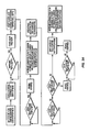
- FIGS. 2A and 2B are flowcharts of exemplary control routines executed by a controller such as that illustrated in the embodiments of dual utilization liquid and gaseous fuel reformers of FIGS. 1A and 1B for managing the operation of the reformers for reforming liquid fuel ( FIG. 2A ) and gaseous fuel ( FIG. 2B ).
- FIGS. 3A and 3B are flowcharts of exemplary control routines executed by a controller such as that illustrated in the embodiments of dual utilization liquid and gaseous fuel reformers of FIGS. 1A and 1B for managing the operation of the reformers when transitioned from reforming liquid fuel to reforming gaseous fuel ( FIG. 3A ) and when transitioning from reforming gaseous fuel to reforming liquid fuel ( FIG. 3B ).
- FIG. 4A is a longitudinal cross section view of an embodiment of dual utilization gaseous and liquid fuel reformer in accordance with the present teachings.
- FIG. 4B illustrates a modification of the reformer of FIG. 4A in accordance with the present teachings whereby the modified reactor comprises a single reactor having a common reaction zone for the reforming of both liquid and gaseous fuels.
- FIG. 5 is longitudinal cross section view of another embodiment of CPOX reformer in accordance with the present teachings featuring the use of heat recovered from an eternal heat source in the operation of the reformer.
- FIGS. 6A and 6B present graphical data showing the relationship between the molar ratios of oxygen to carbon of liquid fuel (diesel) and gaseous fuel (propane) reforming reaction mixtures within the respective liquid fuel and gaseous fuel reforming reaction zone(s) of the dual utilization gaseous and liquid, fuel CPOX reformer of the present teachings at varying percentages of maximum fuel conversion capacity when the reformer is operating in a steady-state mode.
- the reformers and methods of the present teachings should be understood to be suitable to carry out steam reforming and auto thermal reforming, for example, within the same structure and components and/or with the same general methods as described herein. That is, the reformers and methods of the present teachings can deliver the appropriate liquid reactants, for example, liquid reformable fuel and/or liquid water, from a liquid reformable fuel reservoir to a vaporizer to create a vaporized liquid reformable fuel and steam, respectively, and the appropriate gaseous reactants, for example, at least one of an oxygen-containing gas, a gaseous reformable fuel and steam, from their respective sources to a desired component of a fuel cell unit or system.
- various liquid reactants can be delivered through the liquid delivery part of the system and various gaseous reactants can be delivered through the gas delivery part of the system.
- recycled heat from one or more of a reformer, a fuel cell stack and an afterburner of a fuel cell unit or system can be used to vaporize the water to create steam, which can be present in the delivery system and/or introduced into the delivery system from an independent source.
- compositions are described as having, including or comprising specific components, or where methods are described as having, including, or comprising specific method steps, it is contemplated that such compositions also consist essentially of, or consist of, the recited components and that such methods also consist essentially of, or consist of the recited method steps.
- an element or component can be any one of the recited elements or components, or the element or component can be selected from a group consisting of two or more of the recited elements or components.
- elements and/or features of a composition, an apparatus, or a method described herein can be combined in a variety of ways without departing from the focus and scope of the present teachings whether explicit or implicit therein. For example, where reference is made to a particular structure, that structure can be used in various embodiments of the apparatus and/or method of the present teachings.
- values are disclosed in groups or in ranges. It is specifically intended that a range of numerical values disclosed herein include each and every value within the range and any subrange thereof.
- a numerical value within the range of 0 to 40 is specifically intended to individually disclose 0, 1, 2, 3, 4, 5, 6, 7, 8, 9, 10, 11, 12, 13, 14, 15, 16, 17, 18, 19, 20, 21, 22, 23, 24, 25, 26, 27, 28, 29, 30, 31, 32, 33, 34, 35, 36, 37, 38, 39 and 40, and any subrange thereof, for example, from 0 to 20, from 10 to 30, from 20 to 40, etc.
- a “reformable fuel” refers to a liquid reformable fuel and/or a gaseous reformable fuel.
- ceramic in addition to its art-recognized meaning, shall be understood herein to include glasses, glass-ceramics and cermets (i.e., ceramic-metal composites).
- gas permeable as it applies to a wall of a CPOX reactor unit herein shall be understood to mean a wall structure that is permeable to gaseous CPOX reaction mixtures and gaseous product reformate including, without limitation, the vaporized liquid reformable fuel component of the gaseous CPOX reaction mixture and the hydrogen component of the product reformate.
- liquid reformable fuel shall be understood to include reformable carbon- and hydrogen-containing fuels that are a liquid at standard temperature and pressure (STP) conditions, for example, methanol, ethanol, naphtha, distillate, gasoline, kerosene, jet fuel, diesel, biodiesel, and the like, that when subjected to reforming undergo conversion to hydrogen-rich reformates.
- STP standard temperature and pressure
- liquid reformable fuel shall be further understood to include such fuels whether they are in the liquid state or in the gaseous state, i.e., a vapor.
- gaseous reforming reaction mixture refers to a mixture including a gaseous liquid reformable fuel (e.g., a vaporized liquid reformable fuel), a gaseous reformable fuel or combinations thereof, and an oxygen-containing gas (e.g., air) and/or water (e.g., in the form of steam).
- a gaseous reforming reaction mixture can be subjected to a reforming reaction to create a hydrogen-rich product (“reformate”), which also can contain carbon monoxide.
- reformate hydrogen-rich product
- the gaseous reforming reaction mixture can be referred to a “gaseous CPOX reforming reaction mixture,” which includes a reformable fuel and an oxygen-containing gas.
- the gaseous reforming reaction mixture can be referred to as a “gaseous steam reforming reaction mixture,” which includes a reformable fuel and steam.
- a gaseous steam reforming reaction mixture which includes a reformable fuel and steam.
- an autothermal reforming reaction is to be carried out, the gaseous reforming reaction mixture can be referred to as a “gaseous AT reforming reaction mixture,” which includes a reformable fuel, an oxygen-containing gas and steam.
- gaseous reformable fuel shall be understood to include reformable carbon- and hydrogen-containing fuels that are a gas at STP conditions, for example, methane, ethane, propane, butane, isobutane, ethylene, propylene, butylene, isobutylene, dimethyl ether, their mixtures, such as natural gas and liquefied natural gas (LNG), which are mainly methane, and petroleum gas and liquefied petroleum gas (LPG), which are mainly propane or butane but include all mixtures made up primarily of propane and butane, ammonia, and the like, that when subjected to reforming undergo conversion to hydrogen-rich reformates.
- LNG natural gas and liquefied natural gas
- LPG petroleum gas and liquefied petroleum gas
- reforming reaction shall be understood to include the exothermic and/or endothermic reaction(s) that occur during the conversion of a gaseous reaction medium to a hydrogen-rich reformate.
- the expression “reforming reaction” herein therefore includes, for example, CPOX, autothermal and steam reforming.
- CPOX reaction shall be understood to include the reaction(s) that occur during catalytic partial oxidation reforming or conversion of a reformable fuel to a hydrogen-rich reformate.
- gaseous CPOX reaction mixture refers to a mixture of gaseous reformable fuel or vaporized liquid reformable fuel and an oxygen-containing gas, for example, air.
- open gaseous flow passageway refers to a conduit or channel for the passage of gas therethrough where a solid, including a porous solid or material, is not present across the entire cross-sectional plane of the conduit or channel, i.e., a conduit of channel free of solids, including porous solids.
- CPOX catalyst including a porous catalyst such as a monolith
- Such a structure is distinct from passageways that are packed with a porous catalyst.
- An open gaseous flow passageway can also be present in a CPOX reactor unit which can be defined as a tube which defines a hollow bore, or a cylindrical substrate defining a hollow bore therethrough along its longitudinal axis.
- the hollow bore can be considered an open gaseous flow passageway.
- an open gaseous flow passageway usually can extend along a longitudinal axis of a CPOX reactor unit
- a tortuous conduit or channel is also contemplated by the present teachings and can be capable of having an open gaseous flow passageway provided that the tortuous conduit or channel is free of solids across a cross-sectional plane of the CPOX reactor unit. It should also be understood that the cross-sectional dimension(s) of an open gaseous flow passageway can vary along its longitudinal axis or along the tortuous conduit or channel.
- cold start-up mode of reforming shall be understood herein to refer to a start-up mode of operation of the reformer wherein there is little or no heat recoverable from a previous reforming operation.
- a reformer at essentially ambient temperature requires a cold start-up mode of operation before it can enter into a steady-state mode of reforming.
- hot start-up mode of operation of reforming shall be understood herein to refer to a start-up mode of operation of the reformer wherein residual heat recovered from a previous exothermic reforming operation is effectively utilized to facilitate transitioning from the processing of liquid fuel to the processing of gaseous fuel and, conversely, transitioning from the processing of gaseous fuel to the processing of liquid fuel.
- the dual utilization liquid and gaseous fuel reformer and method of reforming herein are capable of processing either a liquid or gaseous fuel and after a shut-down period during which heat of exotherm produced by reforming has largely dissipated, for example, to such an extent that the reactor has reached ambient or near-ambient air temperature, and thereafter switching over to operating on the other type of fuel.
- the reformer and method of reforming herein are also capable of initially processing liquid fuel and thereafter transitioning to processing gaseous fuel, in this way utilizing heat of exotherm recovered from the conversion of liquid fuel to reformate, possibly augmented by additional heat supplied, for example, by an electrical resistance heater unit, to initiate the conversion of gaseous fuel.
- the reactor and method of reforming herein are also capable of initially processing gaseous fuel and thereafter transitioning to processing liquid fuel, this time utilizing heat of exotherm recovered from the conversion of gaseous fuel, with or without additional heat, to vaporize the liquid fuel and heat the reforming reaction zone prior to conducting the conversion of the liquid fuel to reformate.
- a vaporizer for vaporizing liquid reformable fuel is in fluid flow communication with the inlet of the reforming reaction zone wherein conversation of the liquid fuel to reformate is made to take place.
- the vaporizer can be operated to eliminate or reduce the risk of heating the fuel to a temperature at or above its flash point and/or causing appreciable pyrolysis of fuel.
- an igniter for initiating the reaction within a reforming reaction zone is in thermal communication with a reforming reaction zone.
- the dual utilization liquid and gaseous fuel reformer herein can comprise a single reaction zone, or in other embodiments, a plurality, or array, of spaced-apart tubular reforming reactor units, each reactor unit having its own reforming reaction zone.
- a hydrogen barrier can be attached to the external surface of at least the wall section of such tubular reforming reactor unit corresponding to its reforming reaction zone in order to prevent or inhibit the loss of hydrogen therefrom.
- the dual utilization liquid and gaseous fuel reformer of the present teachings can include a conduit for managing the flow of gas(es) to its reforming reaction zone(s).
- the conduit can include an inlet for the admission of oxygen-containing gas, an inlet for the admission of liquid fuel, vaporized liquid fuel or both, an inlet for the admission of gaseous fuel or mixture of oxygen-containing gas and gaseous fuel, and an outlet for gaseous reforming reaction mixture.
- the conduit is advantageously U-shaped for a more compact reformer configuration.
- the reformer herein can have a split routing system for directing the flow of the oxygen-containing gas component of the gaseous reforming reaction mixture where one portion of the oxygen-containing gas can be combined with vaporized liquid in order to provide a relatively fuel-rich gaseous reaction mixture which is resistant to flashing and another portion of the oxygen-containing gas can be combined with the fuel-rich reaction mixture such as to provide a gaseous reforming reaction mixture that comes within a preset molar ratio of oxygen to carbon for a desired CPOX reforming reaction.
- a manifold, or plenum, in fluid communication with the inlets of reforming reactor units comprising the aforedescribed plurality, or array, of such units can be configured to provide a more uniform distribution of gaseous reforming reaction mixture thereto, for example, at a substantially uniform composition, at a substantially uniform temperature and/or at a substantially uniform rate.
- the manifold can have a housing or enclosure that defines a manifold chamber.
- the manifold or manifold chamber can include a gas distributor, for example, a gas distributor disposed within the manifold chamber, for more evenly distributing gaseous reforming reaction mixture to the inlets of the reforming reactor units.
- the manifold housing, or manifold enclosure can be fabricated from a relatively low cost, readily moldable thermoplastic or thermosetting resin and/or can feature “cold seal” connections between its outlets and the inlets of the CPOX reactor units.
- the reformer of the present teachings includes a first heating zone and first heater thermally linked thereto operable during a start-up mode of operation of the reformer to heat oxygen-containing gas introduced into the conduit within an initial range of elevated temperature.
- the reformer also includes a second heating zone and internal or external source of heat thermally linked thereto operable during a steady-state mode of operation of the reformer to heat oxygen-containing gas to within an initial range of elevated temperature.
- the reformer of the present teachings can also include a third heating zone and second heater thermally linked thereto operable during start-up and steady-state modes of operation of the reformer to heat oxygen-containing gas to within a further elevated range of elevated temperature.
- the reformer of the present teachings can include a mixer, for example, a static mixer, disposed within a mixing zone, in order to more uniformly mix oxygen-containing gas and vaporized liquid reformable fuel.
- a mixer for example, a static mixer, disposed within a mixing zone, in order to more uniformly mix oxygen-containing gas and vaporized liquid reformable fuel.
- the reformer of the present teachings can include a reformate processing unit or device, for example, a carbon monoxide removal device to reduce the carbon monoxide content of the product reformate.
- a reformate processing unit or device can include a water gas shift converter, a preferential oxidation reactor, and/or a hydrogen-selective membrane for separating reformate into a hydrogen stream and a carbon monoxide-containing stream.
- the reformer of the present teachings can include one or more outlets for hydrogen-rich reformate directly connected to inlet(s) of another device, for example, a fuel cell.
- a reformer of the present teachings can include thermal insulation for reducing heat loss from the reforming reaction zone(s) and/or other heat-radiating components of the reformer.
- the reformer of the present teachings can include a gaseous stream driver for driving gaseous flow to, within and/or through the reformer.
- the gaseous stream driver can be a single centrifugal blower unit or a blower system comprising a series of interconnected blower units.
- a blower or blower unit in a series can include a casing having an axial inlet and a radial outlet, an impeller disposed within the casing for drawing in a gas, for example, an oxygen-containing gas such as air, in the axial inlet and expelling the gas through the radial outlet; and a motor for driving the impeller.
- the blower can draw in a gas at a first pressure and expel the gas at a second, for example, higher, pressure.
- a blower can also include a duct connecting the radial outlet of at least one blower unit in the series with the axial inlet of at least one other blower unit in the series.
- a reformer of the present teachings can include a liquid fuel pump.
- suitable liquid fuel pumps include metering pumps, rotary pumps, impeller pumps, diaphragm pumps, peristaltic pumps, positive displacement pumps, gear pumps, piezoelectric pumps, electrokinetic pumps, electroosmotic pumps, capillary pumps and the like.
- a reformer of the present teachings can include one or more sensor assemblies for monitoring and controlling reformer operation.
- sensor assemblies include flow meters, thermocouples, thermistors and resistance temperature detectors.
- a reformer of the present teachings also can include a controller for automating the operation of the reformer in its start-up, steady-state and/or shut-down modes.
- the controller can include a plurality of sensor assemblies such as those aforementioned in communication therewith.
- FIGS. 1A and 1B illustrate embodiments of the dual utilization liquid and gaseous fuel CPOX reformer in accordance with the present teachings.
- dual utilization liquid and gaseous fuel CPOX reformer 100 includes centrifugal blower 102 for introducing oxygen-containing gas, exemplified here and in the other embodiments of the present teachings by air, into conduit 103 , and for driving this and other gaseous streams (inclusive of vaporized fuel-air mixture(s) and hydrogen-rich reformates) through the various passageways, including the open gaseous flow passageways of tubular CPOX reactor units 109 of the reformer.
- Conduit 103 can include flow meter 104 and thermocouple 105 . These and similar devices can be placed at various locations within CPOX reformer 100 in order to measure, monitor and control the operation of the reformer as more fully explained below in connection with controller 126 .
- start-up mode of operation of CPOX reformer 100 in which a first gaseous CPOX reaction mixture (i.e., oxygen-containing gas and vaporized liquid fuel) is made to undergo conversion to hydrogen-rich reformate, air at ambient temperature, introduced by blower 102 into conduit 103 , passes through first heating zone 106 , where the air is initially heated by first heater 107 , for example, of the electrical resistance type, to within a preset, or targeted, first range of elevated temperature at a given rate of flow.
- a first gaseous CPOX reaction mixture i.e., oxygen-containing gas and vaporized liquid fuel
- the initially heated air then passes through heat transfer zone 108 which in the steady-state mode of operation of CPOX reformer 100 is heated by heat of exotherm recovered from the CPOX reaction occurring within CPOX reaction zones 110 of tubular CPOX reactor units 109 .
- the thermal output of first heater 107 can be reduced or its operation discontinued since the incoming air will have already been heated by passage through heat transfer zone 108 to within, or approaching, its first range of elevated temperature.
- the air which has initially been heated passes through second heating zone 111 where it is further heated by second heater 112 , which can also be of the electrical resistance type, to within a second range of elevated temperature.
- Second heater 112 operates to top-off the temperature of the previously heated air thereby satisfying several operational requirements of CPOX reformer 100 when processing liquid fuel, namely, assisting in the regulation and fine-tuning of the thermal requirements of the reformer on a rapid response and as-needed basis, providing sufficient heat for the subsequent vaporization of liquid reformable fuel introduced further downstream into conduit 103 and providing heated gaseous CPOX reaction mixture.
- Liquid reformable fuel exemplified here and in other embodiments of the present teachings by diesel, is continuously introduced from storage via pump 113 through fuel fine 114 , equipped with optional flow meter 115 and optional flow control valve 116 , and into conduit 103 where the fuel is vaporized by vaporizer system 117 utilizing heat provided by heated air flowing from second heating zone 111 .
- the vaporized, i.e., gaseous, fuel combines with the stream of heated air in mixing zone 118 of conduit 103 .
- a mixer for example, a static mixer such as in-line mixer 119 , and/or vortex-creating helical grooves formed within the internal surface of conduit 103 , or an externally powered mixer (not shown), are disposed within mixing zone 118 of conduit 103 in order to provide a more uniform vaporized liquid fuel-air gaseous CPOX reaction mixture than would otherwise be the case.
- the heated vaporized liquid fuel-air CPOX reaction mixture enters manifold, or plenum, 120 which functions to distribute the reaction mixture more evenly and, for example, at a more uniform temperature, into tubular CPOX reactor units 109 . While the conduit and the manifold will ordinarily be surrounded by thermal insulation (e.g., insulation 410 of CPOX reformer 400 illustrated in FIG. 4A ), the CPOX reaction mixture can still undergo a drop in temperature due to heat loss through the walls of the manifold, which typically has a greater volume, and hence a greater wall surface area, than that of a comparable length of conduit 103 . Another factor that can cause a drop in the temperature of the CPOX reaction mixture within manifold 120 is the reduction in pressure and velocity which the reaction mixture undergoes as it exits conduit 103 and enters the larger space of manifold 120 .
- a manifold can be provided with means for maintaining the temperature of the gaseous CPOX reaction mixture above the condensation threshold of its vaporized fuel component.
- heater 121 of the electrical resistance type, and thermocouple or thermistor probe 122 for purposes of temperature control are disposed within manifold 120 in order to accomplish this objective.
- a reformer can be provided with thermally conductive structure(s), (e.g., thermally conductive elements 434 of the CPOX reformer illustrated in FIG. 4A ) for transferring heat of exotherm recovered from the CPOX reaction occurring within CPOX reaction zones 110 of tubular CPOX reactor units 109 to such locations within the manifold where the potential for condensation of fuel vapor can be greatest, for example, wall surfaces in the vicinity of the fuel-air outlets and/or other sites such as corners and other recesses of the manifold that could cause localized condensation of vaporized fuel.
- thermally conductive structure(s) e.g., thermally conductive elements 434 of the CPOX reformer illustrated in FIG. 4A
- the heated CPOX reaction mixture is introduced into tubular CPOX reactor units 109 .
- igniter 123 initiates the CPOX reaction of the gaseous CPOX reaction mixture within CPOX reaction zones 110 of tubular CPOX reactor units 109 thereby commencing the production of hydrogen-rich reformats.
- steady-state CPOX reaction temperatures e.g., 250° C. to 1,100° C.
- Thermocouples 124 and 125 are provided to monitor the temperatures of, respectively, the vaporization operation occurring within conduit 103 and the CPOX reaction occurring within CPOX reactor units 109 , the temperature measurements being relayed as monitored parameters to reformer control system 126 .
- air introduced by blower 102 into conduit 103 combines with gaseous reformable fuel, exemplified here and in the other embodiments of the present teachings by propane, introduced into conduit 103 at a relatively low pressure from gaseous fuel storage tank 131 through gaseous fuel line 132 equipped with optional thermocouple 133 , flow meter 134 and flow control valve 135 .
- the propane-air mixture then enters first heating zone 106 where it is heated to gaseous fuel CPOX reaction temperature by first heater 107 , effectively functioning as an igniter for the CPOX reaction mixture, thereby commencing the production of hydrogen-rich reformate.
- First heating zone 106 may be disposed proximate to gaseous fuel CPOX reaction zone 138 (as shown) or be partly or completely coincident therewith. Gaseous fuel CPOX reaction zone 138 is shown as coincident with heat transfer zone 108 .
- CPOX reactor 100 When CPOX reactor 100 is operated in such manner as to transition from a steady-state mode of liquid fuel CPOX reforming to a “hot” start-up mode of gaseous fuel CPOX reforming, residual heat recovered from CPOX reaction zones 110 of tubular CPOX reactor units 109 , with or without the input of additional heat, is transferred to heat transfer zone 108 , and therefore CPOX reaction zone 138 , where such heat serves to ignite the air-propane mixture commencing the production of hydrogen rich reformate.
- CPOX reactor 100 when CPOX reactor 100 is operated in such manner as to transition from a steady state mode of gaseous fuel CPOX reforming to a “hot” start-up mode of liquid fuel CPOX reforming, residual heat recovered from CPOX reaction zone 138 , with or without the input of additional heat, is transferred to air introduced into conduit 103 , the heated air then being utilized to vaporize liquid fuel as previously explained in connection with liquid fuel CPOX operation of the reactor, and to preheat CPOX reaction zones 110 of CPOX reactor units 109 .
- heat transfer zone 108 of CPOX reactor 100 is provided to transfer heat recovered from CPOX reaction taking place within CPOX reaction zones 110 to gas(es) flowing through zone 108
- CPOX reaction zones 110 of tubular CPOX reactor units 109 function as a single, shared or common CPOX reaction zone selectively operable to process liquid or gaseous CPOX fuel.
- CPOX reactor 150 illustrated in FIG. 1B is essentially identical to CPOX reactor 100 shown in FIG. 1A except that in the former, gaseous fuel line 132 connects to inlet 160 of duct 161 connecting centrifugal blower units 162 and 163 of centrifugal blower system 164 whereas in the latter, gaseous fuel line 132 connects to inlet 103 at mixing zone 136 occupied by static mixer 137 .
- air drawn into blower unit 162 on being expelled therefrom combines with gaseous fuel introduced through inlet 160 info duct 161 , the gaseous fuel-air stream then entering blower unit 163 where it is expelled therefrom as a well-mixed uniform CPOX reaction medium.
- This arrangement advantageously dispenses with mixing zone 136 and static mixer 137 of CPOX reactor 100 of FIG. 1A while providing perhaps an even more uniform reaction mixture, one formed without an accompanying increase in back pressure.
- product effluent or hydrogen-rich reformate from liquid CPOX reformer 100 can be introduced into one or more conventional or otherwise known carbon monoxide removal devices 128 for the reduction of its carbon monoxide (CO) content, for example, where the product effluent is to be introduced as fuel to a fuel cell stack utilizing a catalyst that is particularly susceptible to poisoning by CO, for example, a polymer electrolyte membrane fuel cell.
- the product effluent can be introduced into a water gas shift (WGS) converter wherein CO is converted to carbon dioxide (CO 2 ) while at the same time producing additional hydrogen, or the product effluent can be introduced into a reactor wherein CO is made to undergo preferential oxidation (PROX) to CO 2 .
- WGS water gas shift
- PROX preferential oxidation
- CO reduction can also be carried out employing a combination of these processes, for example, WGS followed by PROX and vice versa.
- Units/devices of this kind can also be combined with one or more other CG-reduction units such as the aforementioned WGS converter and/or PROX reactor.
- Reformer 100 can also include a source of electrical current, for example, rechargeable lithium-ion battery system 127 , to provide power for its electrically driven components such as blower 102 , flow meters 104 and 115 , heaters 107 , 112 and 121 , liquid fuel pump 113 , flow control valves 116 and 135 , igniter 123 , and thermocouples 105 , 122 , 124 , 125 and 133 , and, if desired, to store surplus electricity for later use.
- a source of electrical current for example, rechargeable lithium-ion battery system 127 , to provide power for its electrically driven components such as blower 102 , flow meters 104 and 115 , heaters 107 , 112 and 121 , liquid fuel pump 113 , flow control valves 116 and 135 , igniter 123 , and thermocouples 105 , 122 , 124 , 125 and 133 , and, if desired, to store surplus electricity for later use.
- Controller 126 is provided for controlling the operations of a liquid fuel CPOX reformer 100 in its start-up, steady-state and shut-down modes, when operation.
- the controller can be software operating on a processor. However, it is within the scope of the present teachings to employ a controller that is implemented with one or more digital or analog circuits, or combinations thereof.
- Controller 126 further includes a plurality of sensor assemblies, for example, flow meters 104 and 115 , thermocouples 105 , 122 , 124 , 125 and 133 , and the like, in communication with the controller and adapted to monitor selected operating parameters of CPOX reformer 100 .
- sensor assemblies for example, flow meters 104 and 115 , thermocouples 105 , 122 , 124 , 125 and 133 , and the like, in communication with the controller and adapted to monitor selected operating parameters of CPOX reformer 100 .
- controller 126 can manage the operations of the CPOX reformer in accordance with the present teachings. More specifically, controller 126 can communicate with a control signal-receiving portion of the desired section or component of CPOX reformer 100 by sending command signals thereto directing a particular action.
- controller 126 can, for example, send control signals to liquid fuel pump 113 and/or liquid fuel flow control valve 116 , to control the flow of liquid fuel through fuel line 114 to conduit 103 , to centrifugal blower 102 to control the flow of air into conduit 103 and drive the flow of heated gaseous CPOX reaction mixture within and through CPOX reformer units 109 , to first and second heater units 107 and 112 to control their thermal output, to manifold heater 121 to control its thermal output, to igniter 123 to control its on-off states, and to battery/battery recharger system 127 to manage its functions.
- controller 126 can send control signals to gaseous fuel flow control valve 136 to control the flow of gaseous fuel through line 132 , to centrifugal blower 102 to control the flow of air into conduit 103 , to first and second heater units 107 and 112 and manifold heater 121 to control their on-off states (the off state when reformer 100 is processing gaseous fuel) and igniter 123 to control its on-off state.
- the sensor assemblies, control signal-receiving devices and communication pathways herein can be of any suitable construction such as those known in the art.
- the sensor assemblies can include any suitable sensor devices for the operating parameters being monitored. For example, fuel flow rates can be monitored with any suitable flow meter, pressures can be monitored with any suitable pressure-sensing or pressure-regulating device, and the like.
- the sensor assemblies can also, but do not necessarily, include a transducer in communication with the controller.
- the communication pathways will ordinarily be wired electrical signals but any other suitable form of communication path way can also be employed.
- communication pathways are schematically illustrated as single- or double-headed arrows.
- An arrow terminating at controller 126 schematically represents an input signal such as the value of a measured flow rate or measured temperature.
- An arrow extending from controller 126 schematically represents a control signal sent to direct a responsive action from the component at which the arrow terminates.
- Dual-headed pathways schematically represent that controller 126 not only sends command signals to corresponding components of CPOX reformer 100 to provide a determined responsive action, but also receives operating inputs from CPOX reformer 100 and various components thereof mechanical units such as fuel pump 113 and carbon monoxide removal device 128 .
- FIGS. 2A and 2B present flow charts of exemplary control routines that can be executed by a controller such as controller 126 of FIGS. 1A and 1B to automate the operations of dual utilization liquid and gaseous fuel CPOX reformer in accordance with the present teachings when, respectively, processing liquid fuel and gaseous fuel in accordance with the present teachings.
- FIGS. 3A and 3B present flow charts of exemplary control routines than can be executed by a controller such as controller 126 of FIGS. 1A and 1B to automate the operations of a CPOX reactor herein when, respectively, made to transition from processing liquid fuel to gaseous fuel ( FIG. 3A ) and transition from processing gaseous fuel to liquid fuel ( FIG. 3B ).
- the flow charts can be executed by a controller at a fixed interval, for example, every 10 milliseconds or so.
- the control logic illustrated in FIGS. 2A, 2B, 3A and 3B perform several functions including the management of gaseous flows, healing and fuel vaporization in the case of liquid fuel reforming and reforming reaction temperatures in start-up and steady-state modes of operation and management of the procedure for the shut-down mode of reformer operation.
- air as an oxygen-containing gas is introduced at ambient temperature and at a preset mass flow rate via centrifugal blower system 402 through inlet 403 of main conduit 404 , which includes a generally U-shaped conduit section favoring compactness.
- the ambient temperature air is initially heated in the start-up mode operation of the reformer to within a preset range of elevated temperature by passage through first heating zone 405 supplied with heat from first heater unit 406 .
- First heater unit 406 and second heater unit 413 downstream therefrom can be of a conventional or otherwise known electrical resistance type rated, for example, at from 10 to 80 watts or even greater depending upon the designed range of liquid fuel processing capacity of the reformer. Such heaters are capable of raising the temperature of ambient air introduced into main conduit 404 to a desired level for a relatively wide range of CPOX reformer configurations and operating capacities.
- first heater unit 406 can be shut off, the air introduced into main conduit 404 then being initially heated within heat transfer zone 407 by heal of exotherm recovered from CPOX reaction zones 409 of elongate tubular gas-permeable CPOX reactor units 408 . In this manner, the temperature of the air introduced into conduit 404 can be increased from ambient to within some preset elevated range of temperature with the particular temperature being influenced by a variety of design, i.e., structural and operational, factors as those skilled in the art will readily recognize.
- Thermal insulation 410 for example, of the microporous or alumina-based refractory type, surrounds most of main conduit 404 and those portions of CPOX reactor units 408 corresponding to their CPOX reaction zones 409 in order to reduce thermal losses from these components.
- main conduit 404 As the heated air flows downstream within main conduit 404 , it can be split, or divided, into two streams with one stream continuing to course through main conduit 404 and the other stream being diverted into branch conduit 411 from which it exits to re-enter main conduit 404 at merger zone 421 there to merge with vaporized fuel-air mixing passing from first mixing zone 420 (having a first static mixer and/or a helically-grooved, internal wall surface disposed therein).
- first mixing zone 420 having a first static mixer and/or a helically-grooved, internal wall surface disposed therein).
- the merged gases then enter second mixing zone 422 (similarly having a second static mixture and/or a helically-grooved internal wall surface disposed therein) to provide a gaseous CPOX reaction mixture of fairly uniform composition for introduction through outlet 425 into gas distributor 427 of manifold 426 , the structure and operation of which are more fully described herein.
- the amount of vaporized liquid fuel component contained in the fuel-air mixture that starts to form as just-vaporized fuel and heated air begin to combine can be kept high in proportion to the oxygen content of the air component thus eliminating or reducing the possibility that some region(s) of this non-uniform initial fuel-air mixture will contain a concentration of oxygen that is sufficiently high to support ignition with consequent coke formation.
- the somewhat more uniform fuel-air mixture can then merge with the second heated air stream exiting branch conduit 411 at merger zone 421 thereby satisfying the preset O to C molar ratio of the desired CPOX reaction mixture.
- This fuel-air mixture can then flow through the second static mixer disposed within second mixing zone 422 to provide a more compositionally uniform gaseous CPOX reaction mixture just prior to the mixture entering gas distributor 427 of manifold 426 .
- second heating zone 412 To raise the temperature of the air that had been initially heated by passage through first heating zone 405 and/or heat transfer zone 407 , as the initially heated air continues to flow downstream in main conduit 404 , it is routed through second heating zone 412 supplied with heat from second heater unit 413 . Because second heater unit 413 need only increase the temperature of the initially heated air by a relatively small extent, it can function as an incremental heater capable of making the typically small adjustments in air temperature that are conducive to precise and rapid thermal management of the reformer both with regard to the functioning of its fuel vaporization system, described herein, and its tubular CPOX reactor units 408 .
- a liquid reformable fuel such as any of those mentioned above, and exemplified in this and the other embodiments of the present teachings by diesel fuel, is introduced via fuel line 414 terminating within main conduit 404 in liquid fuel spreader device 415 , for example, wick 416 or spray device (not shown).
- any conventional or otherwise known pump device 418 for introducing liquid fuel to CPOX reformer 400 for example, a metering pump, rotary pump, impeller pump, diaphragm pump, peristaltic pump, positive displacement pump such as a gerotor, gear pump, piezoelectric pump, electrokinetic pump, electroosmotic pump, capillary pump, and the like, can be utilized for this purpose.
- the pressurized liquid fuel can be spread within main conduit 404 by a wick or as a fine spray or otherwise in droplet form by any of such conventional or otherwise known spray devices as fuel injectors, pressurized nozzles, atomizers (including those of the ultrasonic type), nebulizers, and the like.
- First and second heater unit 406 and 413 and fuel spreader device 415 can function in unison to vaporize liquid fuel introduced into main conduit 404 and together constitute the principal components of the fuel vaporizer system of reformer 400 .
- a pump or equivalent device can deliver the fuel on an intermittent or pulsed flow basis or substantially continuous flow.
- a pump or equivalent device can make rapid adjustments in fuel flow rate in response to changing CPOX reformer operating requirements.
- CPOX reformer 400 can use any source of heat for driving vaporization of the liquid fuel during the start-up mode of operation, for example, a heater of the electrical resistance type (as in the case of heaters 406 and 413 ), especially where vaporization of the fuel is made to take place outside main conduit 404
- the embodiment of liquid CPOX reformer illustrated in FIG. 4A employs heater 413 to not only incrementally raise the temperature of the initially heated ambient temperature air but to heat the liquid fuel prior to its introduction into main conduit 404 and to provide sufficient heat for vaporizing the fuel once it enters the conduit.
- This optional provision for healing liquid fuel prior to its introduction into main conduit 404 can make it possible to vaporize a given amount of liquid reformable fuel faster, or a greater amount of liquid fuel within a given time period, than the same vaporizer system operating upon reformable fuel which is at ambient temperature at the time it enters conduit 404 .
- fuel line 414 traverses the wall of main conduit 404 with section 419 of the fuel line being extended in length to prolong the residence time of fuel flowing therein where the fuel line passes through, or is proximate to, second heating zone 412 of main conduit 404 .
- An extended fuel line section can assume a variety of configurations for this purpose, for example, a coiled or helical winding (as shown) or a series of lengthwise folds, disposed on, or proximate to, the exterior surface of main conduit 404 corresponding to second heating zone 412 or any similar such configuration disposed within the interior of the conduit at or near second heating zone 412 .
- extended fuel line section 419 must be in effective heat transfer proximity to second heating zone 412 so as to receive an amount of heat sufficient to raise the temperature of the fuel therein to within some preset range of temperature.
- a portion of the thermal output of heater 413 within second heating zone 412 of main conduit 404 in addition to further heating air flowing within this zone, will transfer to fuel, for example, diesel fuel, flowing within the distal section 419 of fuel line 414 , which distal section of fuel line 414 can be lengthened or extended as shown by section 419 , thereby raising its temperature to within the preset range.
- fuel for example, diesel fuel
- which distal section of fuel line 414 can be lengthened or extended as shown by section 419 , thereby raising its temperature to within the preset range.
- Whichever range of temperature values is chosen for the liquid fuel within the fuel line, it should not exceed the boiling point of the fuel (from 150° C. to 350° C. in the case of diesel) if vapor lock and consequent shut-down of reformer 400 are to be avoided.
- liquid fuel vaporizer In the liquid fuel vaporizer described herein, there is little or no opportunity for the liquid fuel to come into direct contact with a heated surface, for example, that of an electrical resistance heater element, that would pose a risk of raising the temperature of the diesel fuel to or above its flash point, to cause spattering of the fuel rather than its vaporization and/or cause pyrolysis of the fuel resulting in coke formation.
- a heated surface for example, that of an electrical resistance heater element
- the temperature of the diesel fuel can be readily and reliably maintained at a level below its flash point and without significant incidents of spattering or coking.
- Liquid fuel spreader 415 is disposed within main conduit 404 downstream from second heating zone 412 and associated heater 413 and upstream from first mixing zone 420 .
- Thermocouple 423 is disposed within main conduit 404 downstream from the vaporizer in order to monitor the temperature of the vaporized fuel-air mixture beginning to form therein.
- gaseous CPOX reaction mixture exits main conduit 404 through outlet 425 and enters gas distributor 427 of manifold 426 which is configured to provide a more uniform distribution of the reaction mixture to, and within, tubular CPOX reactor units 408 .
- gas distributor 427 of manifold 426 which is configured to provide a more uniform distribution of the reaction mixture to, and within, tubular CPOX reactor units 408 .
- Such an arrangement, or other arrangement within the present teachings can provide a distribution of gaseous CPOX reaction mixture where the difference in flow rate of the gaseous CPOX reaction mixture within any two CPOX reactor units is not greater than about 20 percent, for example, not greater than about 10 percent, or not greater than about 5 percent.
- Manifold 426 includes manifold housing, or enclosure, 428 defining manifold chamber 429 within which heated gaseous CPOX reaction mixture (gas) distributor 427 is connected to outlet 425 of main conduit 404 .
- Heated gaseous CPOX reaction mixture exiting main conduit 404 through outlet 425 enters gas distributor 427 thereafter passing outwardly through apertures (e.g., holes or slots) 430 located at the bottom or lower part of the gas distributor, the gas then flowing around the exterior surface of the distributor to its top or upper part and from there into inlets 431 of tubular CPOX reactor units 408 .
- apertures e.g., holes or slots
- electrical resistance heater 432 and thermocouple 433 can be disposed within manifold chamber 429 , for example, on one or more of its internal surfaces or embedded within one or more of its walls, to provide an active heater system for maintaining the temperature within the chamber above the fuel condensation, temperature.
- a passive heat transfer system comprising thermally conductive elements 434 , for example, fabricated from a good conductor of heat such as copper, thermally linking CPOX reaction zones 409 of tubular CPOX reactor units 408 with manifold chamber 429 can be arranged within reformer 400 to convey heat of exotherm from CPOX reaction zones 409 to regions and/or surfaces within manifold chamber 429 so as to maintain the temperature of the vaporized fuel therein above its condensation temperature.
- such active and/or passive heating systems can serve to make the temperature of the gaseous CPOX reaction mixture more uniform as it is introduced into inlets of CPOX reactor units with consequent benefits for both reformer operation and control.
- one or both manifold heating systems can be operated to provide a gaseous CPOX reaction mixture of consistently uniform temperature throughout a manifold chamber such that there will be not more than about a 10% difference, for example, not more than about a 5% difference, in the temperature of gaseous CPOX reaction mixture entering any two tubular CPOX reactor units.
- Some specific factors that can bear upon the optimization of the design of manifold 426 for accomplishing its function of promoting a more uniform distribution of gaseous CPOX reaction mixture to CPOX reactor units 408 include the configuration of its housing 428 , the volume of its chamber 429 and the dimensions of gas distributor 427 including the number, design and placement of its apertures 430 . Such factors in turn depend on such reformer design and operational factors as the target flow rates of gaseous CPOX reaction mixture within a conduit, the number and arrangement of CPOX reactor units 408 , the shape and dimensions of inlets 431 of CPOX reactor units 408 , and similar considerations.
- a manifold of optimal fuel-air distribution performance for a particular liquid fuel CPOX reformer in accordance with the present teachings can be readily constructed by those skilled in the art employing routine testing methods.
- heated gaseous CPOX reaction mixture enters inlets 431 of CPOX reactor units 408 and into CPOX reaction zones 409 where the reaction mixture undergoes a gas phase CPOX reaction to produce a hydrogen-rich, carbon monoxide-containing reformate.
- one or more igniters 435 initiates CPOX. After CPOX becomes self-sustaining, for example, when the temperature of the reaction zone reaches from about 250° C. to about 1100° C., the igniter(s) can be shut off as external ignition is no longer required to maintain the now self-sustaining CPOX reaction.
- dual utilization liquid and gaseous fuel reformer 400 includes structural components that enable it to selectively process gaseous reformable fuels, a capability that optimizes fuel management where both types of reformable fuel are available, for example, but not necessarily at the same time, or for facilitating a subsequent hot start-up mode of operation with liquid fuel.
- This, a relatively brief period of gaseous fuel CPOX reforming can prepare the CPOX reactor for transitioning to a hot start-up mode of liquid fuel CPOX reforming and a quick entry into the steady-state mode of liquid fuel CPOX reforming.
- reformer 400 includes gaseous reformable fuel line 441 and gaseous fuel inlet 442 through which a gaseous fuel such as methane or natural gas or propane is introduced into main conduit 404 at a location therein which is downstream from centrifugal blower system 402 and inlet 403 and upstream from static mixer 436 disposed within mixing zone 437 .
- the gaseous fuel combines with the previously introduced ambient temperature air by passing through mixing zone 437 , the resulting gaseous fuel-air mixture then passing through first heating zone 405 where it is heated to CPOX reaction temperature and then into CPOX reactor zone 443 (essentially coincident with heat transfer zone 407 ).
- Gas-permeable CPOX catalyst-containing support 444 for example, a close-fitting sleeve, insert, lining or coating provided as a porous refractory metal and/or ceramic material, is disposed within CPOX reactor zone 443 of main conduit 404 and extends for at least part of the length, or the full length, of heat transfer zone 407 .
- the fuel-air mixture heated within first heating zone 405 during a start-up mode of operation to a temperature sufficient to initiate CPOX, or to a CPOX-initiating temperature within heat transfer zone 407 during a steady-state mode of operation, undergoes CPOX upon contact with CPOX catalyst-containing support 444 to provide hydrogen-rich reformats.
- gas-permeable CPOX catalyst-containing support 444 within heat transfer zone 407 of main conduit 404 allows CPOX reforming of gaseous fuel to proceed therein under the milder temperature conditions that are typical of the more efficient CPOX conversion of gaseous fuels (e.g., from about 600° C. to about 850° C.) in contrast to the higher temperature regimes of the less efficient CPOX conversion of liquid reformable fuels such as diesel (e.g., from about 650° C. to 1,100° C.).
- Conducting gaseous fuel CPOX reforming-within CPOX catalyst-containing support 444 at the aforementioned lower temperatures has the considerable advantage of reducing the risk of cracking of the fuel and consequent coke formation on the surfaces of the (main) conduit and CPOX reactor units. Such events would be more likely to occur and lead to CPOX reformer failure were the gaseous fuel to be added directly to a CPOX reaction zone with or following the introduction of vaporized fuel-air mixtures therein. Therefore, the CPOX reformers herein, transitioning from the sole processing of gaseous fuel and back again following a period of liquid reformable fuel CPOX conversion can be readily and smoothly accomplished without risk to the integrity of the CPOX reformer and its proper functioning.
- An open gaseous flow passageway can allow for the substantially unimpeded flow of gaseous CPOX reaction mixture and hydrogen-containing reformate therein, a structural feature of CPOX reactor units of the present teachings that contributes to the low back pressure which is characteristic of the operation of liquid fuel CPOX reformers of the present teachings.
- back pressures of not more than about 3 inches of water (0.0075 bar), for example, not more than about 2 inches of water, or not more than about 1 inch of water, are readily achievable.
- a hydrogen barrier is advantageously attached to an outer surface of the wall for at least that portion of its length corresponding to CPOX reaction zone 409 .
- Materials capable of functioning as effective hydrogen barriers must be thermally stable at the high temperatures typical of CPOX reactions and sufficiently dense so as to prevent or deter permeation or diffusion of reformate gases, particularly hydrogen, beyond the external surface of the all corresponding to CPOX reaction zone 409 .
- a variety of ceramic materials (inclusive of glasses and glass-ceramics) and metals meeting these requirements are known and are therefore suitable for providing the hydrogen barrier.
- Specific materials for the hydrogen barrier include, for example, aluminum, nickel, molybdenum, tin, chromium, alumina, recrystallized alumina, aluminides, alumino-silicates, titania, titanium carbide, titanium nitride, boron nitride, magnesium, oxide, chromium oxide, zirconium phosphate, ceria, zirconia, mulite and the like, admixtures thereof and layered combinations thereof.
- Materials from which the catalytically active wall structure of a CPOX reaction zone of a tubular CPOX reactor unit can be fabricated are those that enable such wall structures to remain stable under the high temperatures and oxidative environments characteristic of CPOX reactions.
- Conventional and otherwise known refractory metals, refractory ceramics, and combinations thereof can be used for the construction of the catalytically active wall structure of a CPOX reaction zone.
- Some of these materials, for example, perovskites can also possess catalytic activity impartial oxidation and therefore can be useful not only for the fabrication of the catatytically active wall structure of a CPOX reaction zone but can also supply part or even all of the CPOX catalyst for such structure.
- CPOX catalysts that can be utilized herein are the metals, metal alloys, metal oxides, mixed metal oxides, perovskites, pyrochlores, their mixtures and combinations, including various ones of which are disclosed, for example, in U.S. Pat. Nos. 5,149,156; 5,447,705; 6,379,586; 6,402,989; 6,458,334; 6,488,907; 6,702,960; 6,726,853; 6,878,667; 7,070,752; 7,090,826; 7,328,691; 7,585,810; 7,888,278; 8,062,800; and, 8,241,600, the entire contents of which are incorporated by reference herein.
- CPOX catalysts While numerous highly active noble metal-containing CPOX catalysts are known and as such can be useful herein, they are generally less often employed than other known types of CPOX catalysts due to their high cost, their tendency to sinter at high temperatures and consequently undergo a reduction in catalytic activity, and their proneness to poisoning by sulfur.
- Perovskite catalysts are a class of CPOX catalyst useful in the present teachings as they are also suitable for the construction of the catalytically active wall structures of a CPOX reactor unit.
- Perovskite catalysts are characterized by the structure ABX 3 where “A” and “B” are cations of very different sizes and “X” is an anion, generally oxygen, that bonds to both cations.
- suitable perovskite CPOX catalysts include LaNiO 3 , LaCoO 3 , LaCrO 3 , LaFeO 3 and LaMnO 3 .
- A-site modification of the perovskites generally affects their thermal stability while B-site modification generally affects their catalytic activity.
- Perovskites can be tailor-modified for particular CPOX reaction conditions by doping at their A and/or B sites. Doping results in the atomic level dispersion of the active dopant within the perovskite lattice thereby inhibiting degradations in their catalytic performance. Perovskites can also exhibit excellent tolerance to sulfur at high temperatures characteristic of CPOX reforming.
- doped perovskites useful as CPOX catalysts include La 1 ⁇ x Ce x FeO 3 , LaCr 1 ⁇ y Ru y O 3 , La 1 ⁇ x Sr x Al 1 ⁇ y Ru y O 3 and La 1 ⁇ x Sr x FeO 3 wherein x and y are numbers ranging, for example, from 0.01 to 0.5, from 0.05 to 0.2, etc., depending on the solubility limit and cost of the dopants.
- the outlets of two or more CPOX reactor units of a multitubular CPOX reformer can be in fluid communication with each other (and with additional outlets of CPOX reactor units) and the hydrogen-rich reformate from the outlets can be combined prior to introduction into a fuel cell.
- the hydrogen-rich reformate effluent from two or more CPOX reactor units can be combined in a manifold or similar device and/or one or more conduits and then introduced into a fuel cell, which can be a multitubular fuel cell or a single fuel cell unit.
- a CPOX reformer of the present teachings can be adapted to various applications depending on its end use, for example, providing hydrogen-rich reformate to a single or multitubular fuel cell unit.
- a multiple centrifugal blower system of this construction possesses the ability to make rapid adjustments in the volume of air introduced into a conduit and/or in the rate of flow of the gaseous fuel-air mixture to CPOX reactor units in response to changes in the demand for product hydrogen-rich reformate that single centrifugal blowers of comparable air flow capacity are incapable of providing, as explained herein, without resorting to blowers of relatively high power consumption.
- CPOX reformer 500 of FIG. 5 differs from CPOX reformer 400 of FIG. 4A primarily in the manner in which the air component and/or liquid reformable fuel component of the gaseous CPOX reaction mixture are heated during the steady-state mode of operation of the reformer.
- CPOX reformer 500 a pressurized flow of ambient temperature air provided by centrifugal blower system 501 is introduced into, and passes through, heat exchanger 502 through which is circulated a flow of heat exchange fluid, for example, hot gases from an external heat-producing source such as the afterburner section of a fuel cell stack (not shown).
- This arrangement differs from the provision for heating air in CPOX reformer 400 of FIG.
- CPOX reformer 500 in which ambient air entering the reformer during the steady-state mode of operation of the reformer passes through heat transfer zone 407 of main conduit 404 , the air being heated within zone 407 by heat recovered from the exotherm of the CPOX reaction occurring within CPOX reaction zones 409 of CPOX reactor units 408 .
- a section of fuel line can be routed through heat exchanger 502 to similarly provide heating of the fuel prior to its vaporization.
- CPOX reformer 500 can operate in essentially the same way as CPOX reformer 400 .
- FIGS. 6A and 6B present graphical data demonstrating the relationship between the oxygen (O) to carbon (C) molar ratio of vaporized diesel fuel-air CPOX reaction mixtures and CPOX reaction temperature.
- O oxygen
- C carbon
- FIGS. 6A and 6B present graphical data demonstrating the relationship between the oxygen (O) to carbon (C) molar ratio of vaporized diesel fuel-air CPOX reaction mixtures and CPOX reaction temperature.
- gaseous CPOX reaction mixtures having higher O to C molar ratios can be utilized during the start-up mode of operation of the reformer.
- the higher operating temperatures associated with fuel-lean CPOX reaction mixtures can facilitate a more rapid increase in CPOX catalyst temperature and reduced time to steady-state operation.
- a fuel-lean ratio tends to help inhibit coke formation before the CPOX catalyst has attained its optimum temperature and become fully activated.
- Reducing the O to C molar ratio lowers the catalyst temperature and can enable more fuel to be processed without losing thermal control of the CPOX reactor units and in turn, the fuel vaporizer unit.
- the opposite action can be taken for the shut-down operation, i.e., fuel flow is reduced at a maintained O to C molar ratio.
- the temperature of the CPOX reaction zone(s) of the reformer begin to approach or fall below a temperature resulting in coke formation, for example, below about 650° C
- the O to C molar ratio can be increased to prevent or minimize coking as the CPOX catalyst deactivates.
- the CPOX reformer can be shut down when the temperature of the CPOX reaction mixture falls below about 500° C.
- the flow of oxygen-containing gas can be continued for up to about 15 to 20 seconds or so after fuel flow has been discontinued.
- a shut-down procedure can allow for vaporization and removal of fuel from the reformer that can be contained within a conduit or a section of fuel line between a fuel control valve and locus of introduction of the fuel into the conduit.
- This control characteristic can be influenced by various reformer components including the particular vaporizer system and controller unit components utilized in a specific reformer design.
- the O to C molar ratio of the fuel-air CPOX reaction mixture can be controlled during the operation to tailor its output thermal conditions, with the understanding that changing the O to C molar ratio can result in changes to the quality and/or composition of the reformate.
- Different CPOX catalysts can affect the operational windows and CPOX temperatures.
- different fuels gaseous or liquid
- steam can be introduced into the reformer so that the reformer may be operated to carry out autothermal and/or steam reforming reaction(s).
- the reformer can be initially operated to perform CPOX conversion of a liquid or gaseous reformable fuel thereby providing heat of exotherm that, with or without additional heat, for example, supplied by an electric heater, can be recovered to produce steam in a steam generator.
- the thus-generated steam can be introduced into the reformer in one or more locations therein.
- One suitable location is the vaporizer where the steam can provide heat to vaporize liquid fuel.
- steam introduced into wick 415 in reformer 400 illustrated in FIG. 4 can provide heat for vaporizing liquid fuel on wick surfaces at the same time helping to eliminate or suppress clogging of such surfaces.
- a reformer in accordance with the present teachings can be connected to a fuel cell stack in which hydrogen-rich reformate from the reformer is converted to electrical current. Operation of the fuel cell stack, and where present an associated afterburner unit, can provide source(s) of waste heat that can be recovered and utilized for the operation of a steam generator, again, with or without additional heat such as that supplied by an electric heater. The steam from the steam generator can then be introduced into the reformer, for example, through wick 415 of reformer 400 of FIG. 4 , to support autothermal or steam reforming.
- the source(s) of waste heat referred to can supply the necessary heat to drive endothermic reaction(s) that are involved in autothermal and steam reforming processes.
- the delivery systems of the present teachings can deliver the appropriate reactants for carrying out reforming reactions including partial oxidation (“POX”) reforming such as catalytic partial oxidation (“CPOX”) reforming, steam reforming, and autothermal (“AT”) reforming.
- POX partial oxidation
- CPOX catalytic partial oxidation
- AT autothermal
- the liquid reactants such as liquid reformable fuels and water can be delivered from and through the “liquid reformable fuel” delivery components, conduits, and assemblies of the delivery system.
- the gaseous reactants such as gaseous reformable fuels, steam, and an oxygen-containing gas such as air can be delivered from and through the “gaseous reformable fuel” delivery components, conduits, and assemblies of the delivery system.
- Certain gaseous reactants such as steam and an oxygen-containing gas can be delivered from and through components and assemblies that are peripheral or secondary to the delivery systems of the present teachings, for example, an oxygen-containing gas can be delivered from a source of oxygen-containing gas that is independently in operable fluid communication with at least one of a vaporizer, a reformer, and a fuel cell stack of a fuel cell unit or system, for example, to mix with a liquid reformable fuel and/or a vaporized liquid reformable fuel prior to reforming.
- a source of oxygen-containing gas that is independently in operable fluid communication with at least one of a vaporizer, a reformer, and a fuel cell stack of a fuel cell unit or system, for example, to mix with a liquid reformable fuel and/or a vaporized liquid reformable fuel prior to reforming.
Landscapes
- Chemical & Material Sciences (AREA)
- Chemical Kinetics & Catalysis (AREA)
- Organic Chemistry (AREA)
- Engineering & Computer Science (AREA)
- Combustion & Propulsion (AREA)
- Sustainable Energy (AREA)
- Manufacturing & Machinery (AREA)
- Sustainable Development (AREA)
- Life Sciences & Earth Sciences (AREA)
- Electrochemistry (AREA)
- General Chemical & Material Sciences (AREA)
- Health & Medical Sciences (AREA)
- General Health & Medical Sciences (AREA)
- Inorganic Chemistry (AREA)
- Hydrogen, Water And Hydrids (AREA)
- Physical Or Chemical Processes And Apparatus (AREA)
- Devices And Processes Conducted In The Presence Of Fluids And Solid Particles (AREA)
- Fuel Cell (AREA)
Abstract
Description
-
- a liquid fuel gas phase reforming reaction zone;
- a gaseous fuel gas phase reforming reaction zone;
- a gas flow conduit comprising an oxygen-containing gas inlet, a liquid fuel inlet, a gaseous fuel inlet or oxygen-containing gas and gaseous fuel reforming reaction mixture inlet, a first heating zone thermally coupled to a first heater, a second heating zone thermally coupled to an internal and/or external source of heat, a liquid fuel vaporizer, and a gaseous reforming reaction mixture outlet in gas-flow communication with the liquid fuel and gaseous fuel reforming reaction zones;
- a gaseous reforming reaction mixture igniter in thermal communication with each of the liquid and gaseous fuel reforming reaction zones; and,
- a hydrogen-rich reformate outlet.
-
- (a) reforming first gaseous reforming reaction mixture comprising oxygen-containing gas and vaporized liquid fuel within the first or common reforming reaction zone to produce hydrogen-rich reformate;
- (b) before or after reforming step (a), reforming second gaseous reforming reaction mixture comprising oxygen-containing gas and gaseous fuel within the second or common reforming reaction zone to produce hydrogen-rich reformate; and,
- (c) transitioning from reforming step (a) to reforming step (b) such that heat recovered from reforming step (a), with or without additional heat, is utilized to initiate reforming step (b), or transitioning from reforming step (b) to reforming step (a) such that heat recovered from reforming step (b), with or without additional heat, is utilized to vaporize liquid fuel and heat the second or common reforming reaction zone before the start of reforming step (a).
Claims (21)
Priority Applications (1)
| Application Number | Priority Date | Filing Date | Title |
|---|---|---|---|
| US15/034,000 US10364150B2 (en) | 2013-11-06 | 2014-11-06 | Duel utilization liquid and gaseous fuel reformer and method of reforming |
Applications Claiming Priority (4)
| Application Number | Priority Date | Filing Date | Title |
|---|---|---|---|
| US201361900510P | 2013-11-06 | 2013-11-06 | |
| US201361900543P | 2013-11-06 | 2013-11-06 | |
| PCT/US2014/064362 WO2015069907A2 (en) | 2013-11-06 | 2014-11-06 | Dual utilization liquid and gaseous fuel reformer and method of reforming |
| US15/034,000 US10364150B2 (en) | 2013-11-06 | 2014-11-06 | Duel utilization liquid and gaseous fuel reformer and method of reforming |
Publications (2)
| Publication Number | Publication Date |
|---|---|
| US20160280540A1 US20160280540A1 (en) | 2016-09-29 |
| US10364150B2 true US10364150B2 (en) | 2019-07-30 |
Family
ID=52003046
Family Applications (4)
| Application Number | Title | Priority Date | Filing Date |
|---|---|---|---|
| US15/033,812 Active 2035-02-27 US10106406B2 (en) | 2013-11-06 | 2014-11-05 | Chemical reactor with manifold for management of a flow of gaseous reaction medium thereto |
| US15/034,000 Active US10364150B2 (en) | 2013-11-06 | 2014-11-06 | Duel utilization liquid and gaseous fuel reformer and method of reforming |
| US15/033,997 Active US10414650B2 (en) | 2013-11-06 | 2014-11-06 | Multi-tubular chemical reactor with igniter for initiation of gas phase exothermic reactions |
| US16/515,608 Active US10858247B2 (en) | 2013-11-06 | 2019-07-18 | Multi-tubular chemical reactor with igniter for initiation of gas phase exothermic reactions |
Family Applications Before (1)
| Application Number | Title | Priority Date | Filing Date |
|---|---|---|---|
| US15/033,812 Active 2035-02-27 US10106406B2 (en) | 2013-11-06 | 2014-11-05 | Chemical reactor with manifold for management of a flow of gaseous reaction medium thereto |
Family Applications After (2)
| Application Number | Title | Priority Date | Filing Date |
|---|---|---|---|
| US15/033,997 Active US10414650B2 (en) | 2013-11-06 | 2014-11-06 | Multi-tubular chemical reactor with igniter for initiation of gas phase exothermic reactions |
| US16/515,608 Active US10858247B2 (en) | 2013-11-06 | 2019-07-18 | Multi-tubular chemical reactor with igniter for initiation of gas phase exothermic reactions |
Country Status (9)
| Country | Link |
|---|---|
| US (4) | US10106406B2 (en) |
| EP (3) | EP3065861A2 (en) |
| JP (3) | JP6357242B2 (en) |
| KR (3) | KR101832864B1 (en) |
| CN (4) | CN105706281B (en) |
| AU (4) | AU2014346844B2 (en) |
| CA (3) | CA2929816C (en) |
| MX (4) | MX387047B (en) |
| WO (3) | WO2015069762A2 (en) |
Cited By (1)
| Publication number | Priority date | Publication date | Assignee | Title |
|---|---|---|---|---|
| US20250116208A1 (en) * | 2023-10-10 | 2025-04-10 | Ge Avio S.R.L. | Lubrication system for a turbine engine |
Families Citing this family (19)
| Publication number | Priority date | Publication date | Assignee | Title |
|---|---|---|---|---|
| CA2975831C (en) * | 2015-03-16 | 2020-04-28 | WATT Fuel Cell Corp | Centrifugal blower system with internal gas mixing and gas phase chemical reactor incorporating same |
| CN108778988B (en) * | 2016-02-04 | 2022-08-19 | 法国德西尼布 | Method for reducing temperature spread in a reformer |
| CN106242978B (en) * | 2016-07-28 | 2018-08-31 | 南京工业大学 | Method for preparing antioxidant 6PPD by using micro-reaction device |
| DE102016122777A1 (en) * | 2016-11-25 | 2018-05-30 | Frima International Ag | Cooking appliance |
| CA3082685A1 (en) * | 2017-11-16 | 2019-05-23 | Societe De Commercialisation Des Produits De La Recherche Appliquee Socpra Sciences Et Genie S.E.C. | Integrated solar micro-reactors for hydrogen synthesis via steam methane reforming |
| US11682777B2 (en) | 2017-12-12 | 2023-06-20 | Kent State University | Multifunctional manifold for electrochemical devices and methods for making the same |
| US11235304B2 (en) | 2018-03-27 | 2022-02-01 | Kaneka Corporation | Flow reactor and manufacturing facility comprising the flow reactor |
| KR102075671B1 (en) * | 2018-04-06 | 2020-02-10 | 서울시립대학교 산학협력단 | Method and apparatus for demethylation |
| KR102550860B1 (en) * | 2018-08-30 | 2023-07-04 | 와트 퓨얼 셀 코퍼레이션 | Containers for reformers and fuel cell systems |
| US12359327B2 (en) * | 2018-10-29 | 2025-07-15 | Battelle Energy Alliance, Llc | Electrochemical cells for hydrogen gas production and electricity generation, and related systems and methods |
| CN118204012A (en) * | 2019-08-29 | 2024-06-18 | 瓦特燃料电池公司 | Multitube chemical reactor with igniter for initiating exothermic gas phase reaction |
| EP3862076A1 (en) | 2020-02-10 | 2021-08-11 | Linde GmbH | Reactor and method for performing a chemical reaction |
| EP3878546A1 (en) | 2020-03-13 | 2021-09-15 | Linde GmbH | Reactor and method for performing a chemical reaction |
| EP3900817A1 (en) | 2020-04-23 | 2021-10-27 | Linde GmbH | Reactor and method for performing a chemical reaction |
| CN113188129B (en) * | 2020-12-25 | 2022-08-05 | 中国科学院广州能源研究所 | Method and device for removing pollutants by organic solid waste pyrolysis coupling chemical chain combustion |
| KR102541322B1 (en) * | 2021-03-29 | 2023-06-12 | (주)바이오프랜즈 | Apparatus for hydrogen prodution |
| WO2023034253A1 (en) | 2021-08-31 | 2023-03-09 | Lummus Technology Llc | Methods and systems for performing oxidative coupling of methane |
| CN115838849B (en) * | 2022-12-08 | 2025-06-27 | 一重集团大连工程技术有限公司 | Method and device for obtaining the minimum boost temperature of CrMo steel hydrogenation reactor |
| US12341226B1 (en) | 2024-08-07 | 2025-06-24 | Watt Fuel Cell Corp. | Integrated CPOX/stream reformer and fuel cell system |
Citations (181)
| Publication number | Priority date | Publication date | Assignee | Title |
|---|---|---|---|---|
| US2945077A (en) | 1955-12-01 | 1960-07-12 | Phillips Petroleum Co | Process and apparatus for pressure and temperature control system |
| US3516284A (en) | 1968-06-19 | 1970-06-23 | Nasa | Leak detector |
| US3560167A (en) | 1968-12-18 | 1971-02-02 | Air Prod & Chem | Upflow catalytic reactor for fluid hydrocarbons |
| GB1314984A (en) | 1969-08-21 | 1973-04-26 | Chemical Construction Corp | Process for recovering and using waste heat in the steam reforming |
| US4588659A (en) | 1984-12-11 | 1986-05-13 | Energy Research Corporation | Fuel vaporizer |
| US4751057A (en) | 1985-07-02 | 1988-06-14 | Shell Oil Company | Catalytic conversion of gas or liquid in a miltitube reactor |
| US4894205A (en) | 1987-09-18 | 1990-01-16 | Shell Oil Company | Multitube reactor |
| US5149156A (en) | 1991-03-16 | 1992-09-22 | Kiekert Gmbh & Co. | Power door-lock actuator with pivoting rocker and connecting gears |
| US5149516A (en) | 1990-10-15 | 1992-09-22 | Mobil Oil Corp. | Partial oxidation of methane over perovskite catalyst |
| US5447705A (en) | 1992-09-28 | 1995-09-05 | Institut Francais Du Petrole | Oxidation catalyst and process for the partial oxidation of methane |
| US5527631A (en) | 1994-02-18 | 1996-06-18 | Westinghouse Electric Corporation | Hydrocarbon reforming catalyst material and configuration of the same |
| US5573737A (en) | 1994-09-27 | 1996-11-12 | The United States Of America As Represented By The United States Department Of Energy | Functionally gradient material for membrane reactors to convert methane gas into value-added products |
| US5596514A (en) | 1994-03-17 | 1997-01-21 | Tridelta Industries, Inc. | Electronic control system for a heating apparatus |
| JPH09502694A (en) | 1993-12-01 | 1997-03-18 | テキサコ・デベロップメント・コーポレーション | Production of hydrogen-rich gas |
| US5648582A (en) | 1993-08-20 | 1997-07-15 | Regents Of The University Of Minnesota | Stable, ultra-low residence time partial oxidation |
| US5690763A (en) | 1993-03-19 | 1997-11-25 | E. I. Du Pont De Nemours And Company | Integrated chemical processing apparatus and processes for the preparation thereof |
| WO1998041394A1 (en) | 1997-03-20 | 1998-09-24 | Exxon Research And Engineering Company | Multi-layer membrane composites and their use in hydrocarbon partial oxidation |
| US6033793A (en) | 1996-11-01 | 2000-03-07 | Hydrogen Burner Technology, Inc. | Integrated power module |
| US6284398B1 (en) | 1997-11-04 | 2001-09-04 | Koji Kiryu | Reformer for a fuel cell |
| US6296814B1 (en) | 1998-11-10 | 2001-10-02 | International Fuel Cells, L.L.C. | Hydrocarbon fuel gas reformer assembly for a fuel cell power plant |
| US6379586B1 (en) | 1998-10-20 | 2002-04-30 | The Boc Group, Inc. | Hydrocarbon partial oxidation process |
| US6383469B1 (en) | 1999-02-23 | 2002-05-07 | Xcellsis Gmbh | Device for utilizing heat which is formed during a catalytic reaction |
| US6383670B1 (en) | 1999-10-06 | 2002-05-07 | Idatech, Llc | System and method for controlling the operation of a fuel processing system |
| US6402989B1 (en) | 1999-07-30 | 2002-06-11 | Conoco Inc. | Catalytic partial oxidation process and promoted nickel based catalysts supported on magnesium oxide |
| US6403049B1 (en) | 1997-09-25 | 2002-06-11 | Johnson Matthey Public Limited Company | Hydrogen purification |
| US6447940B1 (en) | 1999-06-15 | 2002-09-10 | Honda Giken Kogyo Kabushiki Kaisha | Evaporation control method for liquid fuel in fuel cell system |
| US6458334B1 (en) | 2000-03-02 | 2002-10-01 | The Boc Group, Inc. | Catalytic partial oxidation of hydrocarbons |
| US6465118B1 (en) | 2000-01-03 | 2002-10-15 | Idatech, Llc | System and method for recovering thermal energy from a fuel processing system |
| US6488907B1 (en) | 1999-07-30 | 2002-12-03 | Conoco Inc. | Catalytic partial oxidation processes and catalysts with diffusion barrier coating |
| US6488838B1 (en) | 1999-08-17 | 2002-12-03 | Battelle Memorial Institute | Chemical reactor and method for gas phase reactant catalytic reactions |
| US6492050B1 (en) | 1997-10-01 | 2002-12-10 | Acumentrics Corporation | Integrated solid oxide fuel cell and reformer |
| WO2002099917A2 (en) | 2001-06-04 | 2002-12-12 | Acumentrics Corporation | Horizontal solid oxide fuel cell tube systems and methods |
| US6521204B1 (en) | 2000-07-27 | 2003-02-18 | General Motors Corporation | Method for operating a combination partial oxidation and steam reforming fuel processor |
| US20030054215A1 (en) | 2001-09-20 | 2003-03-20 | Honeywell International, Inc. | Compact integrated solid oxide fuel cell system |
| US20030064259A1 (en) | 2001-10-01 | 2003-04-03 | Gittleman Craig S. | Method of delivering fuel and air to a fuel cell system |
| US6565817B1 (en) | 1997-09-04 | 2003-05-20 | Aisin Seiki Kabushiki Kaisha | Reformer for a fuel cell |
| US6576359B2 (en) | 1999-10-15 | 2003-06-10 | General Motors Corporation | Controlled air injection for a fuel cell system |
| US6585940B2 (en) | 1998-06-29 | 2003-07-01 | Ngk Insulators, Ltd. | Reformer |
| JP2003272691A (en) | 2002-03-20 | 2003-09-26 | Toshiba International Fuel Cells Corp | Fuel cell generating device and operating method of fuel cell generating device |
| US20030188486A1 (en) | 2002-04-09 | 2003-10-09 | Nissan Motor Co., Ltd. | Fuel reformer |
| US6641795B2 (en) | 1997-10-28 | 2003-11-04 | Ngk Insulators, Ltd. | Reformer and method for operation thereof |
| US6641625B1 (en) | 1999-05-03 | 2003-11-04 | Nuvera Fuel Cells, Inc. | Integrated hydrocarbon reforming system and controls |
| US20030211373A1 (en) | 2002-03-26 | 2003-11-13 | Matsushita Electric Industrial Co., Ltd. | Fuel cell system |
| US20030211021A1 (en) | 2002-05-08 | 2003-11-13 | Nissan Motor Co., Ltd. | Fuel reforming system |
| US20030218991A1 (en) | 2002-05-24 | 2003-11-27 | Besecker Charles J. | Membrane systems containing an oxygen transport membrane and catalyst |
| US6656623B2 (en) | 2001-02-15 | 2003-12-02 | Siemens Westinghouse Power Corporation | Low-cost atmospheric SOFC power generation system |
| US6667123B2 (en) | 1999-11-08 | 2003-12-23 | General Motors Corporation | Down-sized water-gas-shift reactor |
| US20030235726A1 (en) | 2002-06-24 | 2003-12-25 | Kelly Sean M. | Solid-oxide fuel cell system having an integrated reformer and waste energy recovery system |
| US20030234455A1 (en) | 2002-06-24 | 2003-12-25 | Mieney Harry R. | Non-contacting fuel vaporizer |
| US6673270B1 (en) | 1997-10-14 | 2004-01-06 | Shell Oil Company | Process for the preparation of hydrogen and carbon monoxide |
| US20040009104A1 (en) | 2002-07-12 | 2004-01-15 | Andreas Kaupert | Evaporator arrangement, particularly for production of a hydrocarbon/ mixing material mixture, decomposable for hydrogen recovery in a reformer |
| EP1382382A1 (en) | 2002-07-19 | 2004-01-21 | Conoco Phillips Company | Gas distributor comprising a plurality of channels and its use in a catalytic reactor |
| US6692707B1 (en) | 1999-03-03 | 2004-02-17 | Toyota Jidosha Kabushiki Kaisha | Hydrocarbon fuel reformer |
| US6699609B2 (en) | 2000-10-13 | 2004-03-02 | Honda Giken Kogyo Kabushiki Kaisha | Fuel cell system |
| US6702960B1 (en) | 1998-06-30 | 2004-03-09 | Shell Oil Company | Catalytic partial oxidation with a rhodium-iridium alloy catalyst |
| US20040076562A1 (en) | 2002-10-22 | 2004-04-22 | Manzanec Terry J. | Catalysts, in microchannel apparatus, and reactions using same |
| US6726853B2 (en) | 1999-04-05 | 2004-04-27 | Sekiyushigen Kaihatsu Kabushiki Kaisha | Process for producing synthetic gas employing catalyst for reforming |
| US6749958B2 (en) | 2000-07-10 | 2004-06-15 | Global Thermmelectric Inc. | Integrated module for solid oxide fuel cell systems |
| US20040144030A1 (en) | 2003-01-23 | 2004-07-29 | Smaling Rudolf M. | Torch ignited partial oxidation fuel reformer and method of operating the same |
| US6770106B1 (en) | 1999-12-28 | 2004-08-03 | Daikin Industries, Ltd | Partial oxidation reformer |
| US6783742B2 (en) | 1998-01-14 | 2004-08-31 | Nuvera Fuel Cells | Reactor for producing hydrogen from hydrocarbon fuels |
| US6790431B2 (en) | 2002-07-16 | 2004-09-14 | Conocophillips Company | Reactor for temperature moderation |
| US6790247B2 (en) | 2001-04-26 | 2004-09-14 | Texaco Inc. | Compact fuel processor |
| US20040180247A1 (en) | 2001-07-04 | 2004-09-16 | Kazutoshi Higashiyama | Hydrogen producing apparatus and power generating system using it |
| US20040191591A1 (en) | 2003-03-25 | 2004-09-30 | Casio Computer Co., Ltd. | Reforming apparatus |
| US6800387B2 (en) | 2001-05-01 | 2004-10-05 | Honda Giken Kogyo Kabushiki Kaisha | Fuel cell system and method for operating the same |
| WO2004091771A1 (en) | 2003-04-16 | 2004-10-28 | Uhde Gmbh | Microreactor composed of plates and comprising a catalyst |
| US6833208B2 (en) | 2000-11-06 | 2004-12-21 | Honda Giken Kogyo Kabushiki Kaisha | Fuel cell system |
| US6833536B2 (en) | 2002-05-22 | 2004-12-21 | Applera Corporation | Non-contact radiant heating and temperature sensing device for a chemical reaction chamber |
| US20050008907A1 (en) | 2003-05-14 | 2005-01-13 | Kabushiki Kaisha Toshiba | Fuel cell system |
| US20050028445A1 (en) | 2003-07-31 | 2005-02-10 | Subir Roychoudhury | Method and system for catalytic gasification of liquid fuels |
| US6861508B2 (en) | 1996-07-12 | 2005-03-01 | Institut National De La Sante Et De La Recherche Medicale | Transcriptional intermediary factor-2 |
| US20050051444A1 (en) | 2003-09-08 | 2005-03-10 | Thomas Hurt | Utility case |
| US6869456B2 (en) | 2000-06-27 | 2005-03-22 | Delphi Technologies, Inc. | Method for starting a fast light-off catalytic fuel reformer |
| US6872379B2 (en) | 2001-08-15 | 2005-03-29 | Sulzer Hexis Ag | Method for the reformation of fuels, in particular heating oil |
| US20050069485A1 (en) | 2003-09-26 | 2005-03-31 | Korea Institute Of Energy Research | Compact partial oxidation reactor assemblage with fast start-up capability |
| US6878667B2 (en) | 1999-10-18 | 2005-04-12 | Conocophillips Company | Nickel-rhodium based catalysts for synthesis gas production |
| US20050081444A1 (en) | 2003-10-17 | 2005-04-21 | General Electric Company | Catalytic partial oxidation processor with heat exchanger for converting hydrocarbon fuels to syngas for use in fuel cells and method |
| US6887456B2 (en) | 2001-10-05 | 2005-05-03 | Conocophillips Company | Catalyst system for enhanced flow syngas production |
| US6887436B1 (en) | 2000-06-27 | 2005-05-03 | Delphi Technologies, Inc. | Fast light-off catalytic reformer |
| JP2005186203A (en) | 2003-12-25 | 2005-07-14 | Max Co Ltd | Stapler including preliminary staple storing part |
| US20050154046A1 (en) | 2004-01-12 | 2005-07-14 | Longgui Wang | Methods of treating an inflammatory-related disease |
| US6932950B1 (en) | 1998-02-18 | 2005-08-23 | Man Dwe Gmbh | Tubular reactor for catalytic gas phase reactions |
| US20050191533A1 (en) | 2004-02-26 | 2005-09-01 | Ju-Yong Kim | Reformer for fuel cell system and fuel cell system having the same |
| US20050188615A1 (en) | 2004-02-26 | 2005-09-01 | Sennoun Mohammed E. | Integrated fuel processor subsystem with quasi-autothermal reforming |
| US20050267606A1 (en) | 2004-05-25 | 2005-12-01 | Bartlett James R Jr | Process module tuning |
| US6984371B2 (en) | 2002-07-26 | 2006-01-10 | Sud-Chemie Inc. | Process for catalytic reforming |
| US7001867B2 (en) | 2002-05-21 | 2006-02-21 | Conocophillips Company | Rare earth aluminates and gallates supported rhodium catalysts for catalytic partial oxidation of hydrocarbons |
| US20060051634A1 (en) | 2004-09-09 | 2006-03-09 | Genesis Fueltech, Inc. | Power controller for fuel cell |
| WO2006032644A1 (en) | 2004-09-20 | 2006-03-30 | Shell Internationale Research Maatschappij B.V. | A process for the catalytic partial oxidation of a liquid hydrocarbonaceous fuel |
| WO2006034868A1 (en) | 2004-09-30 | 2006-04-06 | Eni S.P.A. | Equipment for the atomisation of a liquid stream by means of a dispersing gaseous stream and for mixing the atomised product with a further suitable gaseous stream in equipment for effecting catalytic partial oxidations and relative catalytic partial oxidation process |
| US7037349B2 (en) | 2002-06-24 | 2006-05-02 | Delphi Technologies, Inc. | Method and apparatus for fuel/air preparation in a fuel cell |
| US7048897B1 (en) | 2000-08-28 | 2006-05-23 | Motorola, Inc. | Hydrogen generator utilizing ceramic technology |
| US20060133976A1 (en) | 2004-12-22 | 2006-06-22 | Male Jonathan L | Catalyst system and method for the reduction of NOx |
| US7070752B2 (en) | 2001-05-01 | 2006-07-04 | The Boc Group, Inc. | Supported perovskite-type oxides and methods for preparation thereof |
| US7070633B2 (en) | 2000-12-22 | 2006-07-04 | Honda Giken Kogyo Kabushiki Kaisha | Fuel gas generating apparatus for a fuel cell |
| US7090826B2 (en) | 2002-12-23 | 2006-08-15 | The Boc Group, Inc. | Monolith based catalytic partial oxidation process for syngas production |
| US20060179717A1 (en) | 2005-02-15 | 2006-08-17 | Labarge William J | Reformer and method of making the same |
| US7101531B2 (en) | 2001-11-16 | 2006-09-05 | Nissan Motor Co., Ltd. | Fuel reforming system and control therefor |
| US7115233B2 (en) | 2001-11-22 | 2006-10-03 | Mitsubishi Denki Kabushiki Kaisha | Reformer |
| US7118717B2 (en) | 2002-09-06 | 2006-10-10 | Engelhard Corporation | Simplified article for carbon monoxide removal |
| US20060246333A1 (en) | 2005-04-27 | 2006-11-02 | Schaevitz Samuel B | Fuel cell apparatus and methods |
| US7132184B2 (en) | 2004-01-19 | 2006-11-07 | Toyota Jidosha Kabushiki Kaisha | Fuel cell system |
| US7147946B2 (en) | 2001-05-23 | 2006-12-12 | Nissan Motor Co., Ltd. | Fuel cell system |
| US7147836B2 (en) | 2000-09-21 | 2006-12-12 | Nucellsys Gmbh | Device for evaporating a liquid |
| US7156866B1 (en) | 2003-10-15 | 2007-01-02 | Riggs Jeffrey M | Holistic method of treating injured or pathologic tissue with a laser |
| US7189371B2 (en) | 2000-06-01 | 2007-03-13 | Nissan Motor Co., Ltd. | Fuel reforming system |
| US7192458B1 (en) | 2001-03-22 | 2007-03-20 | Hyradix Incorporated | Process, control system and apparatus for the distribution of air in a fuel cell/fuel processor system |
| US20070084118A1 (en) | 2003-12-17 | 2007-04-19 | Webasto Ag | Reformer and method for reacting fuel and oxidant to reformate |
| US20070104641A1 (en) | 2005-11-08 | 2007-05-10 | Ahmed M M | Method of controlling oxygen addition to a steam methane reformer |
| EP1787950A2 (en) | 2005-11-17 | 2007-05-23 | Delphi Technologies, Inc. | Fuel reformer and methods for using the same |
| US7232352B2 (en) | 2002-09-10 | 2007-06-19 | Deborah Kutny Splaine | Paddle hand grips and method for making and using same |
| US20070183949A1 (en) | 2006-02-08 | 2007-08-09 | Fischer Bernhard A | Hydrocarbon reformer system including a pleated static mixer |
| US7285247B2 (en) | 2003-10-24 | 2007-10-23 | Arvin Technologies, Inc. | Apparatus and method for operating a fuel reformer so as to purge soot therefrom |
| US7294421B2 (en) | 2001-02-07 | 2007-11-13 | Delphi Technologies, Inc. | Solid oxide auxiliary power unit reformate control |
| US20070289215A1 (en) | 2006-06-19 | 2007-12-20 | John William Hemmings | Method and apparatus for producing synthesis gas |
| JP2008007372A (en) | 2006-06-29 | 2008-01-17 | Nippon Oil Corp | Reformer and indirect internal reforming type solid oxide fuel cell |
| US7323148B2 (en) | 2002-11-05 | 2008-01-29 | Millennium Cell, Inc. | Hydrogen generator |
| US7328691B2 (en) | 2005-09-28 | 2008-02-12 | Kubota Corporation | Multi-cylinder engine |
| US7335432B2 (en) | 2004-04-30 | 2008-02-26 | Motorola, Inc. | Solid oxide fuel cell portable power source |
| WO2008031024A1 (en) | 2006-09-08 | 2008-03-13 | Eltron Research Inc. | Catalytic membrane reactor and method for production of synthesis gas |
| US7364812B2 (en) | 2004-03-19 | 2008-04-29 | Pittsburgh Electric Engines, Inc. | Multi-function solid oxide fuel cell bundle and method of making the same |
| US7368482B2 (en) | 2003-09-11 | 2008-05-06 | Eni S.P.A. | Catalytic partial oxidation process for producing synthesis gas |
| US20080138273A1 (en) | 2006-12-11 | 2008-06-12 | Yi Jiang | Wall flow reactor for hydrogen production |
| US20080152970A1 (en) | 2006-12-22 | 2008-06-26 | Rush Kenneth M | Minimizing coke formation in a reformer |
| US20080187797A1 (en) | 2006-07-10 | 2008-08-07 | Protonex Technology Corporation | Fuel processor for fuel cell systems |
| US7422810B2 (en) | 2004-01-22 | 2008-09-09 | Bloom Energy Corporation | High temperature fuel cell system and method of operating same |
| US20090029205A1 (en) | 2007-07-26 | 2009-01-29 | Bloom Energy Corporation | Integrated fuel line to support CPOX and SMR reactions in SOFC systems |
| US7490580B2 (en) | 2002-07-11 | 2009-02-17 | Honda Motor Co., Ltd. | Vaporizer that vaporizes a liquid to generate vapor |
| US20090104482A1 (en) | 2005-05-23 | 2009-04-23 | Honda Motor Co., Ltd. | Fuel Cell System and Method of Operating the Fuel Cell System |
| US20090208784A1 (en) | 2008-02-19 | 2009-08-20 | Bloom Energy Corporation | Fuel cell system containing anode tail gas oxidizer and hybrid heat exchanger/reformer |
| US7578861B2 (en) | 2004-03-01 | 2009-08-25 | Enerday Gmbh | Reformer and process for reacting fuel and oxidizer into reformate |
| US7585810B2 (en) | 2004-09-01 | 2009-09-08 | Umicore Ag & Co. Kg | Method for partial oxidation of hydrocarbons, catalyst member therefor and method of manufacture |
| WO2009116977A2 (en) | 2007-12-18 | 2009-09-24 | Dow Technology Investments Llc | Tube reactor |
| US20090291335A1 (en) | 2005-01-07 | 2009-11-26 | Iwao Anzai | Method for starting-up solid oxide fuel cell system |
| US7625414B2 (en) | 2003-01-23 | 2009-12-01 | Institut Francais Du Petrole | Partial oxidation reactor |
| US20100015479A1 (en) | 2006-06-01 | 2010-01-21 | Klaus Rusch | Assembly for producing a hydrogenous gas |
| US20100052292A1 (en) | 2002-09-24 | 2010-03-04 | Toshiro Yoshie | Stroller |
| US7691509B2 (en) | 2004-06-23 | 2010-04-06 | Samsung Sdi Co., Ltd. | Reformer and fuel cell system having the same |
| US20100119894A1 (en) | 2007-02-16 | 2010-05-13 | Nippon Oil Corporation | Reformer system, fuel cell system, and their operation method |
| US7736399B2 (en) | 2006-11-07 | 2010-06-15 | Delphi Technologies, Inc. | Electrically-heated metal vaporizer for fuel/air preparation in a hydrocarbon reformer assembly |
| US20100203404A1 (en) | 2007-08-01 | 2010-08-12 | Honda Motor Co., Ltd. | Fuel cell system and method of operating the fuel cell system |
| US7846599B2 (en) | 2007-06-04 | 2010-12-07 | Bloom Energy Corporation | Method for high temperature fuel cell system start up and shutdown |
| US7858214B2 (en) | 2005-09-21 | 2010-12-28 | Delphi Technologies, Inc. | Method and apparatus for light internal reforming in a solid oxide fuel cell system |
| US20100330446A1 (en) | 2007-04-13 | 2010-12-30 | Lucka Klaus | Hydrogen system and method for starting up a hydrogen system |
| US7888278B2 (en) | 2002-11-11 | 2011-02-15 | Conocophillips Company | Stabilized alumina supports, catalysts made therefrom, and their use in partial oxidation |
| US20110039175A1 (en) | 2008-04-24 | 2011-02-17 | Jx Nippon Oil & Energy Corporation | Method for operating indirect internal reforming solid oxide fuel cell system |
| WO2011019825A2 (en) | 2009-08-12 | 2011-02-17 | Bloom Energy Corporation | Internal reforming anode for solid oxide fuel cells |
| US20110165483A1 (en) | 2008-09-08 | 2011-07-07 | Honda Motor Co., Ltd. | Reformer |
| US7976787B2 (en) | 2008-08-20 | 2011-07-12 | Delphi Technologies, Inc. | Fuel cell reformer |
| US7985506B2 (en) | 2007-12-27 | 2011-07-26 | Samsung Sdi Co., Ltd. | Fuel cell system and reformer |
| US7985509B2 (en) | 2004-04-29 | 2011-07-26 | Samsung Sdi Co., Ltd. | Fuel cell system |
| US20110189578A1 (en) | 2010-02-01 | 2011-08-04 | Adaptive Materials, Inc. | Fuel cell system including a resilient manifold interconnecting member |
| US7998456B2 (en) | 2006-10-31 | 2011-08-16 | Shell Oil Company | Process for the production of hydrogen |
| US8034504B2 (en) | 2006-05-18 | 2011-10-11 | Honda Motor Co., Ltd. | Fuel cell system and method of operating same |
| US20110269032A1 (en) | 2010-12-10 | 2011-11-03 | Delphi Technologies, Inc. | Combustor for a fuel cell system |
| US8062800B2 (en) | 2005-07-22 | 2011-11-22 | Samsung Sdi Co., Ltd. | Catalyst for reformer used in fuel cell system, reformer, and fuel cell system comprising same |
| US20120062166A1 (en) | 2009-05-22 | 2012-03-15 | Battelle Memorial Institute | Integrated Fuel Processor and Fuel Cell System Control Method |
| US8142941B2 (en) | 2005-12-19 | 2012-03-27 | Casio Computer Co., Ltd. | Power supply system and control method thereof |
| US20120088167A1 (en) | 2010-10-06 | 2012-04-12 | J. Eberspaecher Gmbh & Co. Kg | Operating method for a fuel cell system |
| US8158289B2 (en) | 2001-04-27 | 2012-04-17 | Cutright Richard H | Integrated high temperature PEM fuel cell system |
| US8173310B2 (en) | 2007-10-30 | 2012-05-08 | Samsung Sdi Co., Ltd. | Fuel cell system and method for operating the same |
| US20120164547A1 (en) | 2007-07-26 | 2012-06-28 | Bloom Energy Corporation | CPOX Reactor Design for Liquid Fuel and Liquid Water |
| US8241600B1 (en) | 2008-04-14 | 2012-08-14 | The United States Of America As Represented By The United States Department Of Energy | Pyrochlore catalysts for hydrocarbon fuel reforming |
| US8257669B2 (en) | 2010-12-22 | 2012-09-04 | Delphi Technologies, Inc. | Multi-tube chemical reactor with tessellated heat transfer fins |
| US8277524B2 (en) | 2004-03-16 | 2012-10-02 | Delphi Technologies, Inc. | Reformer start-up strategy for use in a solid oxide fuel cell control system |
| US8298711B2 (en) | 2005-01-18 | 2012-10-30 | Seiko Instruments Inc. | Method of operating fuel cell system and fuel cell system |
| US8304122B2 (en) | 2009-02-06 | 2012-11-06 | Protonex Technology Corporation | Solid oxide fuel cell systems with hot zones having improved reactant distribution |
| US8318363B2 (en) | 2004-06-29 | 2012-11-27 | Samsung Sdi Co., Ltd. | Reformer for fuel cell system and fuel cell system comprising the same |
| US8323365B2 (en) | 2007-05-22 | 2012-12-04 | Praxair Technology, Inc. | Dual mode reactor SMR integration |
| US20120320969A1 (en) | 2011-06-20 | 2012-12-20 | Qualcomm Incorporated | Unified merge mode and adaptive motion vector prediction mode candidates selection |
| US8337757B2 (en) | 2008-02-07 | 2012-12-25 | Precision Combustion, Inc. | Reactor control method |
| US20120328969A1 (en) | 2011-06-24 | 2012-12-27 | WATT Fuel Cell Corp | Centrifugal blower system and fuel cell incorporating same |
| US8354083B2 (en) | 2003-12-31 | 2013-01-15 | Corning Incorporated | Multi-tubular reactors with monolithic catalysts |
| US20130028815A1 (en) | 2007-11-23 | 2013-01-31 | Eni S.P.A | Process for the production of synthesis gas and hydrogen starting from liquid or gaseous hydrocarbons |
| US20130059223A1 (en) | 2011-09-01 | 2013-03-07 | Watt Fuel Cell Corp. | Process for producing tubular ceramic structures of non-circular cross section |
| US20130056911A1 (en) | 2011-09-01 | 2013-03-07 | Watt Fuel Cell Corp. | Process for producing tubular ceramic structures |
| US20130230787A1 (en) | 2012-03-01 | 2013-09-05 | Watt Fuel Cell Corp. | Tubular solid oxide fuel cell assembly and fuel cell device incorporating same |
| US8557451B2 (en) | 2009-04-10 | 2013-10-15 | Protonex Technology Corporation | Fuel processor for fuel cell systems |
| US20140335483A1 (en) | 2013-05-13 | 2014-11-13 | Google Inc. | Language proficiency detection in social applications |
| JP2015504033A (en) | 2011-10-18 | 2015-02-05 | シエル・インターナシヨネイル・リサーチ・マーチヤツピイ・ベー・ウイShell Internationale Research Maatschappij Beslotenvennootshap | Syngas production |
Family Cites Families (32)
| Publication number | Priority date | Publication date | Assignee | Title |
|---|---|---|---|---|
| FR937605A (en) | 1945-12-21 | 1948-08-23 | Vickers | Force transmission system |
| US3518284A (en) * | 1967-02-20 | 1970-06-30 | Shell Oil Co | Partial oxidation of organic compounds |
| US3560107A (en) | 1968-09-25 | 1971-02-02 | Gen Motors Corp | Cooled airfoil |
| JPS62165461A (en) | 1986-01-16 | 1987-07-22 | Casio Comput Co Ltd | Private call system |
| JPH0513975Y2 (en) * | 1986-04-10 | 1993-04-14 | ||
| ZA911838B (en) * | 1990-04-03 | 1991-12-24 | Standard Oil Co Ohio | Endothermic reaction apparatus |
| US7116717B1 (en) | 1999-12-15 | 2006-10-03 | Bigband Networks, Inc. | Method and system for scalable representation, storage, transmission and reconstruction of media streams |
| US7069435B2 (en) | 2000-12-19 | 2006-06-27 | Tricipher, Inc. | System and method for authentication in a crypto-system utilizing symmetric and asymmetric crypto-keys |
| US6635544B2 (en) | 2001-09-07 | 2003-10-21 | Power Intergrations, Inc. | Method of fabricating a high-voltage transistor with a multi-layered extended drain structure |
| US20030064269A1 (en) | 2001-10-02 | 2003-04-03 | Kelly Sean M. | Fuel cell stack having a featured interconnect element |
| ES2253661T3 (en) * | 2002-02-27 | 2006-06-01 | Basf Aktiengesellschaft | PROCEDURE FOR OBTAINING PHOSGEN. |
| US6881508B2 (en) | 2002-05-30 | 2005-04-19 | Plug Power, Inc. | Apparatus and method for controlling a fuel cell system |
| JP3985771B2 (en) * | 2003-10-27 | 2007-10-03 | トヨタ自動車株式会社 | Fuel reformer and fuel reforming method |
| CN1636860B (en) | 2003-12-26 | 2011-04-20 | 松下电器产业株式会社 | Hydrogen generator and fuel cell system using the same |
| JP4761722B2 (en) * | 2004-03-26 | 2011-08-31 | 京セラ株式会社 | Fuel cell |
| ES2424646T3 (en) | 2004-04-08 | 2013-10-07 | Hsc Development Llc | Follicular Extraction Device |
| KR100599685B1 (en) | 2004-06-30 | 2006-07-13 | 삼성에스디아이 주식회사 | Reformer of fuel cell system and fuel cell system employing same |
| US7261751B2 (en) | 2004-08-06 | 2007-08-28 | Conocophillips Company | Synthesis gas process comprising partial oxidation using controlled and optimized temperature profile |
| JP2006172896A (en) | 2004-12-15 | 2006-06-29 | Aisin Seiki Co Ltd | Fuel cell and fuel cell distribution plate |
| DE102005030416B4 (en) * | 2005-06-30 | 2007-06-21 | Stockhausen Gmbh | Arrangement and method for heating and fumigation of a polymerizable material and apparatus and method for producing high-purity (meth) acrylic acid |
| US7985609B2 (en) | 2006-11-17 | 2011-07-26 | Canon Kabushiki Kaisha | Light-emitting apparatus and production method thereof |
| US7505547B2 (en) | 2006-12-22 | 2009-03-17 | Global Nuclear Fuel-Americas, Llc | Assembly and method for mounting a fuel assembly having a predefined orientation within a nuclear reactor |
| JP2009087684A (en) | 2007-09-28 | 2009-04-23 | Casio Comput Co Ltd | FUEL CELL SYSTEM AND METHOD FOR OPERATION AND CONTROL OF FUEL CELL SYSTEM |
| US8163046B2 (en) * | 2008-03-28 | 2012-04-24 | IFP Energies Nouvelles | Start-up process for a unit for producing highly thermally-integrated hydrogen by reforming a hydrocarbon feedstock |
| TW201011966A (en) | 2008-09-11 | 2010-03-16 | Tatung Co | Fuel cell system and operating method thereof |
| US20100175379A1 (en) * | 2009-01-09 | 2010-07-15 | General Electric Company | Pre-mix catalytic partial oxidation fuel reformer for staged and reheat gas turbine systems |
| US8224622B2 (en) * | 2009-07-27 | 2012-07-17 | Telefonaktiebolaget L M Ericsson (Publ) | Method and apparatus for distribution-independent outlier detection in streaming data |
| US20110195333A1 (en) * | 2010-02-08 | 2011-08-11 | Adaptive Materials, Inc. | Fuel cell stack including internal reforming and electrochemically active segements connected in series |
| US20110223549A1 (en) * | 2010-05-31 | 2011-09-15 | Resource Rex, LLC | Laminar Flow Combustion System and Method for Enhancing Combustion Efficiency |
| EP2637775B1 (en) * | 2010-11-11 | 2016-08-10 | Basf Se | Method and device for producing acetylene and syngas |
| DE102011088483A1 (en) | 2011-12-14 | 2013-06-20 | BSH Bosch und Siemens Hausgeräte GmbH | Household appliance and method |
| KR101213046B1 (en) * | 2012-09-18 | 2012-12-18 | 국방과학연구소 | Controlling method of fuel reformer |
-
2014
- 2014-11-05 CA CA2929816A patent/CA2929816C/en active Active
- 2014-11-05 WO PCT/US2014/064116 patent/WO2015069762A2/en not_active Ceased
- 2014-11-05 KR KR1020167012065A patent/KR101832864B1/en active Active
- 2014-11-05 AU AU2014346844A patent/AU2014346844B2/en active Active
- 2014-11-05 JP JP2016553229A patent/JP6357242B2/en active Active
- 2014-11-05 CN CN201480061178.5A patent/CN105706281B/en active Active
- 2014-11-05 EP EP14815116.0A patent/EP3065861A2/en active Pending
- 2014-11-05 US US15/033,812 patent/US10106406B2/en active Active
- 2014-11-05 MX MX2016005700A patent/MX387047B/en unknown
- 2014-11-06 CA CA2929417A patent/CA2929417C/en active Active
- 2014-11-06 AU AU2014346740A patent/AU2014346740B2/en active Active
- 2014-11-06 EP EP14806120.3A patent/EP3065859A2/en active Pending
- 2014-11-06 JP JP2016553234A patent/JP6286061B2/en active Active
- 2014-11-06 KR KR1020167012732A patent/KR101832865B1/en active Active
- 2014-11-06 WO PCT/US2014/064362 patent/WO2015069907A2/en not_active Ceased
- 2014-11-06 CN CN201910584001.8A patent/CN110302722B/en active Active
- 2014-11-06 JP JP2016553240A patent/JP6204605B2/en active Active
- 2014-11-06 US US15/034,000 patent/US10364150B2/en active Active
- 2014-11-06 KR KR1020167013018A patent/KR101832866B1/en active Active
- 2014-11-06 AU AU2014346722A patent/AU2014346722B2/en active Active
- 2014-11-06 CN CN201480072093.7A patent/CN105874636B/en active Active
- 2014-11-06 CA CA2929544A patent/CA2929544C/en active Active
- 2014-11-06 US US15/033,997 patent/US10414650B2/en active Active
- 2014-11-06 MX MX2016005909A patent/MX387051B/en unknown
- 2014-11-06 EP EP14835598.5A patent/EP3065862A2/en active Pending
- 2014-11-06 CN CN201480061037.3A patent/CN105705225B/en active Active
- 2014-11-06 WO PCT/US2014/064238 patent/WO2015069835A2/en not_active Ceased
- 2014-11-06 MX MX2016005896A patent/MX387380B/en unknown
-
2016
- 2016-05-06 MX MX2021012426A patent/MX2021012426A/en unknown
-
2017
- 2017-11-13 AU AU2017258980A patent/AU2017258980B2/en active Active
-
2019
- 2019-07-18 US US16/515,608 patent/US10858247B2/en active Active
Patent Citations (191)
| Publication number | Priority date | Publication date | Assignee | Title |
|---|---|---|---|---|
| US2945077A (en) | 1955-12-01 | 1960-07-12 | Phillips Petroleum Co | Process and apparatus for pressure and temperature control system |
| US3516284A (en) | 1968-06-19 | 1970-06-23 | Nasa | Leak detector |
| US3560167A (en) | 1968-12-18 | 1971-02-02 | Air Prod & Chem | Upflow catalytic reactor for fluid hydrocarbons |
| GB1314984A (en) | 1969-08-21 | 1973-04-26 | Chemical Construction Corp | Process for recovering and using waste heat in the steam reforming |
| US4588659A (en) | 1984-12-11 | 1986-05-13 | Energy Research Corporation | Fuel vaporizer |
| US4751057A (en) | 1985-07-02 | 1988-06-14 | Shell Oil Company | Catalytic conversion of gas or liquid in a miltitube reactor |
| US4894205A (en) | 1987-09-18 | 1990-01-16 | Shell Oil Company | Multitube reactor |
| US5149516A (en) | 1990-10-15 | 1992-09-22 | Mobil Oil Corp. | Partial oxidation of methane over perovskite catalyst |
| US5149156A (en) | 1991-03-16 | 1992-09-22 | Kiekert Gmbh & Co. | Power door-lock actuator with pivoting rocker and connecting gears |
| US5447705A (en) | 1992-09-28 | 1995-09-05 | Institut Francais Du Petrole | Oxidation catalyst and process for the partial oxidation of methane |
| US5690763A (en) | 1993-03-19 | 1997-11-25 | E. I. Du Pont De Nemours And Company | Integrated chemical processing apparatus and processes for the preparation thereof |
| US5648582A (en) | 1993-08-20 | 1997-07-15 | Regents Of The University Of Minnesota | Stable, ultra-low residence time partial oxidation |
| JPH09502694A (en) | 1993-12-01 | 1997-03-18 | テキサコ・デベロップメント・コーポレーション | Production of hydrogen-rich gas |
| US5527631A (en) | 1994-02-18 | 1996-06-18 | Westinghouse Electric Corporation | Hydrocarbon reforming catalyst material and configuration of the same |
| US5596514A (en) | 1994-03-17 | 1997-01-21 | Tridelta Industries, Inc. | Electronic control system for a heating apparatus |
| US5573737A (en) | 1994-09-27 | 1996-11-12 | The United States Of America As Represented By The United States Department Of Energy | Functionally gradient material for membrane reactors to convert methane gas into value-added products |
| US6861508B2 (en) | 1996-07-12 | 2005-03-01 | Institut National De La Sante Et De La Recherche Medicale | Transcriptional intermediary factor-2 |
| US6033793A (en) | 1996-11-01 | 2000-03-07 | Hydrogen Burner Technology, Inc. | Integrated power module |
| WO1998041394A1 (en) | 1997-03-20 | 1998-09-24 | Exxon Research And Engineering Company | Multi-layer membrane composites and their use in hydrocarbon partial oxidation |
| US6565817B1 (en) | 1997-09-04 | 2003-05-20 | Aisin Seiki Kabushiki Kaisha | Reformer for a fuel cell |
| US6403049B1 (en) | 1997-09-25 | 2002-06-11 | Johnson Matthey Public Limited Company | Hydrogen purification |
| US6492050B1 (en) | 1997-10-01 | 2002-12-10 | Acumentrics Corporation | Integrated solid oxide fuel cell and reformer |
| US6673270B1 (en) | 1997-10-14 | 2004-01-06 | Shell Oil Company | Process for the preparation of hydrogen and carbon monoxide |
| US6641795B2 (en) | 1997-10-28 | 2003-11-04 | Ngk Insulators, Ltd. | Reformer and method for operation thereof |
| US6284398B1 (en) | 1997-11-04 | 2001-09-04 | Koji Kiryu | Reformer for a fuel cell |
| US6783742B2 (en) | 1998-01-14 | 2004-08-31 | Nuvera Fuel Cells | Reactor for producing hydrogen from hydrocarbon fuels |
| US6932950B1 (en) | 1998-02-18 | 2005-08-23 | Man Dwe Gmbh | Tubular reactor for catalytic gas phase reactions |
| US6585940B2 (en) | 1998-06-29 | 2003-07-01 | Ngk Insulators, Ltd. | Reformer |
| US6702960B1 (en) | 1998-06-30 | 2004-03-09 | Shell Oil Company | Catalytic partial oxidation with a rhodium-iridium alloy catalyst |
| US6379586B1 (en) | 1998-10-20 | 2002-04-30 | The Boc Group, Inc. | Hydrocarbon partial oxidation process |
| US6296814B1 (en) | 1998-11-10 | 2001-10-02 | International Fuel Cells, L.L.C. | Hydrocarbon fuel gas reformer assembly for a fuel cell power plant |
| US6383469B1 (en) | 1999-02-23 | 2002-05-07 | Xcellsis Gmbh | Device for utilizing heat which is formed during a catalytic reaction |
| US6692707B1 (en) | 1999-03-03 | 2004-02-17 | Toyota Jidosha Kabushiki Kaisha | Hydrocarbon fuel reformer |
| US6726853B2 (en) | 1999-04-05 | 2004-04-27 | Sekiyushigen Kaihatsu Kabushiki Kaisha | Process for producing synthetic gas employing catalyst for reforming |
| US6641625B1 (en) | 1999-05-03 | 2003-11-04 | Nuvera Fuel Cells, Inc. | Integrated hydrocarbon reforming system and controls |
| US6447940B1 (en) | 1999-06-15 | 2002-09-10 | Honda Giken Kogyo Kabushiki Kaisha | Evaporation control method for liquid fuel in fuel cell system |
| US6402989B1 (en) | 1999-07-30 | 2002-06-11 | Conoco Inc. | Catalytic partial oxidation process and promoted nickel based catalysts supported on magnesium oxide |
| US6488907B1 (en) | 1999-07-30 | 2002-12-03 | Conoco Inc. | Catalytic partial oxidation processes and catalysts with diffusion barrier coating |
| US7632320B2 (en) | 1999-08-17 | 2009-12-15 | Battelle Memorial Institute | Chemical reactor for gas phase reactant catalytic steam reforming reactions |
| US20060067861A1 (en) | 1999-08-17 | 2006-03-30 | Tonkovich Anna L Y | Chemical reactor and method for gas phase reactant catalytic reactions |
| US6488838B1 (en) | 1999-08-17 | 2002-12-03 | Battelle Memorial Institute | Chemical reactor and method for gas phase reactant catalytic reactions |
| US6383670B1 (en) | 1999-10-06 | 2002-05-07 | Idatech, Llc | System and method for controlling the operation of a fuel processing system |
| US6576359B2 (en) | 1999-10-15 | 2003-06-10 | General Motors Corporation | Controlled air injection for a fuel cell system |
| US6878667B2 (en) | 1999-10-18 | 2005-04-12 | Conocophillips Company | Nickel-rhodium based catalysts for synthesis gas production |
| US6667123B2 (en) | 1999-11-08 | 2003-12-23 | General Motors Corporation | Down-sized water-gas-shift reactor |
| US6770106B1 (en) | 1999-12-28 | 2004-08-03 | Daikin Industries, Ltd | Partial oxidation reformer |
| US6465118B1 (en) | 2000-01-03 | 2002-10-15 | Idatech, Llc | System and method for recovering thermal energy from a fuel processing system |
| US6458334B1 (en) | 2000-03-02 | 2002-10-01 | The Boc Group, Inc. | Catalytic partial oxidation of hydrocarbons |
| US7189371B2 (en) | 2000-06-01 | 2007-03-13 | Nissan Motor Co., Ltd. | Fuel reforming system |
| US6887436B1 (en) | 2000-06-27 | 2005-05-03 | Delphi Technologies, Inc. | Fast light-off catalytic reformer |
| US6869456B2 (en) | 2000-06-27 | 2005-03-22 | Delphi Technologies, Inc. | Method for starting a fast light-off catalytic fuel reformer |
| US6749958B2 (en) | 2000-07-10 | 2004-06-15 | Global Thermmelectric Inc. | Integrated module for solid oxide fuel cell systems |
| US6521204B1 (en) | 2000-07-27 | 2003-02-18 | General Motors Corporation | Method for operating a combination partial oxidation and steam reforming fuel processor |
| US7048897B1 (en) | 2000-08-28 | 2006-05-23 | Motorola, Inc. | Hydrogen generator utilizing ceramic technology |
| US7147836B2 (en) | 2000-09-21 | 2006-12-12 | Nucellsys Gmbh | Device for evaporating a liquid |
| US6699609B2 (en) | 2000-10-13 | 2004-03-02 | Honda Giken Kogyo Kabushiki Kaisha | Fuel cell system |
| US6833208B2 (en) | 2000-11-06 | 2004-12-21 | Honda Giken Kogyo Kabushiki Kaisha | Fuel cell system |
| US7070633B2 (en) | 2000-12-22 | 2006-07-04 | Honda Giken Kogyo Kabushiki Kaisha | Fuel gas generating apparatus for a fuel cell |
| US7294421B2 (en) | 2001-02-07 | 2007-11-13 | Delphi Technologies, Inc. | Solid oxide auxiliary power unit reformate control |
| US6656623B2 (en) | 2001-02-15 | 2003-12-02 | Siemens Westinghouse Power Corporation | Low-cost atmospheric SOFC power generation system |
| US7192458B1 (en) | 2001-03-22 | 2007-03-20 | Hyradix Incorporated | Process, control system and apparatus for the distribution of air in a fuel cell/fuel processor system |
| US6790247B2 (en) | 2001-04-26 | 2004-09-14 | Texaco Inc. | Compact fuel processor |
| US8158289B2 (en) | 2001-04-27 | 2012-04-17 | Cutright Richard H | Integrated high temperature PEM fuel cell system |
| US7070752B2 (en) | 2001-05-01 | 2006-07-04 | The Boc Group, Inc. | Supported perovskite-type oxides and methods for preparation thereof |
| US6800387B2 (en) | 2001-05-01 | 2004-10-05 | Honda Giken Kogyo Kabushiki Kaisha | Fuel cell system and method for operating the same |
| US7147946B2 (en) | 2001-05-23 | 2006-12-12 | Nissan Motor Co., Ltd. | Fuel cell system |
| WO2002099917A2 (en) | 2001-06-04 | 2002-12-12 | Acumentrics Corporation | Horizontal solid oxide fuel cell tube systems and methods |
| US20040180247A1 (en) | 2001-07-04 | 2004-09-16 | Kazutoshi Higashiyama | Hydrogen producing apparatus and power generating system using it |
| US6872379B2 (en) | 2001-08-15 | 2005-03-29 | Sulzer Hexis Ag | Method for the reformation of fuels, in particular heating oil |
| US20030054215A1 (en) | 2001-09-20 | 2003-03-20 | Honeywell International, Inc. | Compact integrated solid oxide fuel cell system |
| US20030064259A1 (en) | 2001-10-01 | 2003-04-03 | Gittleman Craig S. | Method of delivering fuel and air to a fuel cell system |
| US6887456B2 (en) | 2001-10-05 | 2005-05-03 | Conocophillips Company | Catalyst system for enhanced flow syngas production |
| US7101531B2 (en) | 2001-11-16 | 2006-09-05 | Nissan Motor Co., Ltd. | Fuel reforming system and control therefor |
| US7115233B2 (en) | 2001-11-22 | 2006-10-03 | Mitsubishi Denki Kabushiki Kaisha | Reformer |
| JP2003272691A (en) | 2002-03-20 | 2003-09-26 | Toshiba International Fuel Cells Corp | Fuel cell generating device and operating method of fuel cell generating device |
| US20030211373A1 (en) | 2002-03-26 | 2003-11-13 | Matsushita Electric Industrial Co., Ltd. | Fuel cell system |
| US20030188486A1 (en) | 2002-04-09 | 2003-10-09 | Nissan Motor Co., Ltd. | Fuel reformer |
| US7344687B2 (en) | 2002-05-08 | 2008-03-18 | Nissan Motor Co., Ltd. | Fuel reforming system |
| US20030211021A1 (en) | 2002-05-08 | 2003-11-13 | Nissan Motor Co., Ltd. | Fuel reforming system |
| US7001867B2 (en) | 2002-05-21 | 2006-02-21 | Conocophillips Company | Rare earth aluminates and gallates supported rhodium catalysts for catalytic partial oxidation of hydrocarbons |
| US6833536B2 (en) | 2002-05-22 | 2004-12-21 | Applera Corporation | Non-contact radiant heating and temperature sensing device for a chemical reaction chamber |
| US20030218991A1 (en) | 2002-05-24 | 2003-11-27 | Besecker Charles J. | Membrane systems containing an oxygen transport membrane and catalyst |
| US7037349B2 (en) | 2002-06-24 | 2006-05-02 | Delphi Technologies, Inc. | Method and apparatus for fuel/air preparation in a fuel cell |
| US6921596B2 (en) | 2002-06-24 | 2005-07-26 | Delphi Technologies, Inc. | Solid-oxide fuel cell system having an integrated reformer and waste energy recovery system |
| US20030235726A1 (en) | 2002-06-24 | 2003-12-25 | Kelly Sean M. | Solid-oxide fuel cell system having an integrated reformer and waste energy recovery system |
| US20030234455A1 (en) | 2002-06-24 | 2003-12-25 | Mieney Harry R. | Non-contacting fuel vaporizer |
| US7490580B2 (en) | 2002-07-11 | 2009-02-17 | Honda Motor Co., Ltd. | Vaporizer that vaporizes a liquid to generate vapor |
| US20040009104A1 (en) | 2002-07-12 | 2004-01-15 | Andreas Kaupert | Evaporator arrangement, particularly for production of a hydrocarbon/ mixing material mixture, decomposable for hydrogen recovery in a reformer |
| JP2004035400A (en) | 2002-07-12 | 2004-02-05 | J Eberspaecher Gmbh & Co Kg | Evaporation apparatus, in particular an evaporation apparatus for producing a hydrocarbon / mixture mixture decomposable to recover hydrogen in a reformer |
| US6790431B2 (en) | 2002-07-16 | 2004-09-14 | Conocophillips Company | Reactor for temperature moderation |
| EP1382382A1 (en) | 2002-07-19 | 2004-01-21 | Conoco Phillips Company | Gas distributor comprising a plurality of channels and its use in a catalytic reactor |
| US6984371B2 (en) | 2002-07-26 | 2006-01-10 | Sud-Chemie Inc. | Process for catalytic reforming |
| US7118717B2 (en) | 2002-09-06 | 2006-10-10 | Engelhard Corporation | Simplified article for carbon monoxide removal |
| US7232352B2 (en) | 2002-09-10 | 2007-06-19 | Deborah Kutny Splaine | Paddle hand grips and method for making and using same |
| US20100052292A1 (en) | 2002-09-24 | 2010-03-04 | Toshiro Yoshie | Stroller |
| US20040076562A1 (en) | 2002-10-22 | 2004-04-22 | Manzanec Terry J. | Catalysts, in microchannel apparatus, and reactions using same |
| US7323148B2 (en) | 2002-11-05 | 2008-01-29 | Millennium Cell, Inc. | Hydrogen generator |
| US7888278B2 (en) | 2002-11-11 | 2011-02-15 | Conocophillips Company | Stabilized alumina supports, catalysts made therefrom, and their use in partial oxidation |
| US7090826B2 (en) | 2002-12-23 | 2006-08-15 | The Boc Group, Inc. | Monolith based catalytic partial oxidation process for syngas production |
| US7625414B2 (en) | 2003-01-23 | 2009-12-01 | Institut Francais Du Petrole | Partial oxidation reactor |
| US20040144030A1 (en) | 2003-01-23 | 2004-07-29 | Smaling Rudolf M. | Torch ignited partial oxidation fuel reformer and method of operating the same |
| US7344572B2 (en) | 2003-03-25 | 2008-03-18 | Casio Computer Co., Ltd. | Reforming apparatus |
| US20040191591A1 (en) | 2003-03-25 | 2004-09-30 | Casio Computer Co., Ltd. | Reforming apparatus |
| WO2004091771A1 (en) | 2003-04-16 | 2004-10-28 | Uhde Gmbh | Microreactor composed of plates and comprising a catalyst |
| US20050008907A1 (en) | 2003-05-14 | 2005-01-13 | Kabushiki Kaisha Toshiba | Fuel cell system |
| US20050028445A1 (en) | 2003-07-31 | 2005-02-10 | Subir Roychoudhury | Method and system for catalytic gasification of liquid fuels |
| US20050051444A1 (en) | 2003-09-08 | 2005-03-10 | Thomas Hurt | Utility case |
| US7368482B2 (en) | 2003-09-11 | 2008-05-06 | Eni S.P.A. | Catalytic partial oxidation process for producing synthesis gas |
| US20050069485A1 (en) | 2003-09-26 | 2005-03-31 | Korea Institute Of Energy Research | Compact partial oxidation reactor assemblage with fast start-up capability |
| US7247258B2 (en) | 2003-09-26 | 2007-07-24 | Korea Institute Of Energy Research | Compact partial oxidation reactor assemblage with fast start-up capability |
| US7156866B1 (en) | 2003-10-15 | 2007-01-02 | Riggs Jeffrey M | Holistic method of treating injured or pathologic tissue with a laser |
| US20050081444A1 (en) | 2003-10-17 | 2005-04-21 | General Electric Company | Catalytic partial oxidation processor with heat exchanger for converting hydrocarbon fuels to syngas for use in fuel cells and method |
| US7285247B2 (en) | 2003-10-24 | 2007-10-23 | Arvin Technologies, Inc. | Apparatus and method for operating a fuel reformer so as to purge soot therefrom |
| US20070084118A1 (en) | 2003-12-17 | 2007-04-19 | Webasto Ag | Reformer and method for reacting fuel and oxidant to reformate |
| JP2005186203A (en) | 2003-12-25 | 2005-07-14 | Max Co Ltd | Stapler including preliminary staple storing part |
| US8354083B2 (en) | 2003-12-31 | 2013-01-15 | Corning Incorporated | Multi-tubular reactors with monolithic catalysts |
| US20050154046A1 (en) | 2004-01-12 | 2005-07-14 | Longgui Wang | Methods of treating an inflammatory-related disease |
| US7132184B2 (en) | 2004-01-19 | 2006-11-07 | Toyota Jidosha Kabushiki Kaisha | Fuel cell system |
| US7901814B2 (en) | 2004-01-22 | 2011-03-08 | Bloom Energy Corporation | High temperature fuel cell system and method of operating same |
| US7704618B2 (en) | 2004-01-22 | 2010-04-27 | Bloom Energy Corporation | High temperature fuel cell system and method of operating same |
| US7422810B2 (en) | 2004-01-22 | 2008-09-09 | Bloom Energy Corporation | High temperature fuel cell system and method of operating same |
| US8486162B2 (en) | 2004-02-26 | 2013-07-16 | Samsung Sdi Co., Ltd. | Reformer for fuel cell system and fuel cell system having the same |
| US20050191533A1 (en) | 2004-02-26 | 2005-09-01 | Ju-Yong Kim | Reformer for fuel cell system and fuel cell system having the same |
| US20050188615A1 (en) | 2004-02-26 | 2005-09-01 | Sennoun Mohammed E. | Integrated fuel processor subsystem with quasi-autothermal reforming |
| US7578861B2 (en) | 2004-03-01 | 2009-08-25 | Enerday Gmbh | Reformer and process for reacting fuel and oxidizer into reformate |
| US8277524B2 (en) | 2004-03-16 | 2012-10-02 | Delphi Technologies, Inc. | Reformer start-up strategy for use in a solid oxide fuel cell control system |
| US7364812B2 (en) | 2004-03-19 | 2008-04-29 | Pittsburgh Electric Engines, Inc. | Multi-function solid oxide fuel cell bundle and method of making the same |
| US7985509B2 (en) | 2004-04-29 | 2011-07-26 | Samsung Sdi Co., Ltd. | Fuel cell system |
| US7335432B2 (en) | 2004-04-30 | 2008-02-26 | Motorola, Inc. | Solid oxide fuel cell portable power source |
| US20050267606A1 (en) | 2004-05-25 | 2005-12-01 | Bartlett James R Jr | Process module tuning |
| US7691509B2 (en) | 2004-06-23 | 2010-04-06 | Samsung Sdi Co., Ltd. | Reformer and fuel cell system having the same |
| US8318363B2 (en) | 2004-06-29 | 2012-11-27 | Samsung Sdi Co., Ltd. | Reformer for fuel cell system and fuel cell system comprising the same |
| US7585810B2 (en) | 2004-09-01 | 2009-09-08 | Umicore Ag & Co. Kg | Method for partial oxidation of hydrocarbons, catalyst member therefor and method of manufacture |
| US20060051634A1 (en) | 2004-09-09 | 2006-03-09 | Genesis Fueltech, Inc. | Power controller for fuel cell |
| WO2006032644A1 (en) | 2004-09-20 | 2006-03-30 | Shell Internationale Research Maatschappij B.V. | A process for the catalytic partial oxidation of a liquid hydrocarbonaceous fuel |
| WO2006034868A1 (en) | 2004-09-30 | 2006-04-06 | Eni S.P.A. | Equipment for the atomisation of a liquid stream by means of a dispersing gaseous stream and for mixing the atomised product with a further suitable gaseous stream in equipment for effecting catalytic partial oxidations and relative catalytic partial oxidation process |
| US20060133976A1 (en) | 2004-12-22 | 2006-06-22 | Male Jonathan L | Catalyst system and method for the reduction of NOx |
| US20090291335A1 (en) | 2005-01-07 | 2009-11-26 | Iwao Anzai | Method for starting-up solid oxide fuel cell system |
| US8298711B2 (en) | 2005-01-18 | 2012-10-30 | Seiko Instruments Inc. | Method of operating fuel cell system and fuel cell system |
| US20060179717A1 (en) | 2005-02-15 | 2006-08-17 | Labarge William J | Reformer and method of making the same |
| US20060246333A1 (en) | 2005-04-27 | 2006-11-02 | Schaevitz Samuel B | Fuel cell apparatus and methods |
| US20090104482A1 (en) | 2005-05-23 | 2009-04-23 | Honda Motor Co., Ltd. | Fuel Cell System and Method of Operating the Fuel Cell System |
| US8062800B2 (en) | 2005-07-22 | 2011-11-22 | Samsung Sdi Co., Ltd. | Catalyst for reformer used in fuel cell system, reformer, and fuel cell system comprising same |
| US7858214B2 (en) | 2005-09-21 | 2010-12-28 | Delphi Technologies, Inc. | Method and apparatus for light internal reforming in a solid oxide fuel cell system |
| US7328691B2 (en) | 2005-09-28 | 2008-02-12 | Kubota Corporation | Multi-cylinder engine |
| US20070104641A1 (en) | 2005-11-08 | 2007-05-10 | Ahmed M M | Method of controlling oxygen addition to a steam methane reformer |
| EP1787950A2 (en) | 2005-11-17 | 2007-05-23 | Delphi Technologies, Inc. | Fuel reformer and methods for using the same |
| US8142941B2 (en) | 2005-12-19 | 2012-03-27 | Casio Computer Co., Ltd. | Power supply system and control method thereof |
| US20070183949A1 (en) | 2006-02-08 | 2007-08-09 | Fischer Bernhard A | Hydrocarbon reformer system including a pleated static mixer |
| US8034504B2 (en) | 2006-05-18 | 2011-10-11 | Honda Motor Co., Ltd. | Fuel cell system and method of operating same |
| US20100015479A1 (en) | 2006-06-01 | 2010-01-21 | Klaus Rusch | Assembly for producing a hydrogenous gas |
| US20070289215A1 (en) | 2006-06-19 | 2007-12-20 | John William Hemmings | Method and apparatus for producing synthesis gas |
| JP2008007372A (en) | 2006-06-29 | 2008-01-17 | Nippon Oil Corp | Reformer and indirect internal reforming type solid oxide fuel cell |
| US20080187797A1 (en) | 2006-07-10 | 2008-08-07 | Protonex Technology Corporation | Fuel processor for fuel cell systems |
| WO2008031024A1 (en) | 2006-09-08 | 2008-03-13 | Eltron Research Inc. | Catalytic membrane reactor and method for production of synthesis gas |
| US7998456B2 (en) | 2006-10-31 | 2011-08-16 | Shell Oil Company | Process for the production of hydrogen |
| US7736399B2 (en) | 2006-11-07 | 2010-06-15 | Delphi Technologies, Inc. | Electrically-heated metal vaporizer for fuel/air preparation in a hydrocarbon reformer assembly |
| US20080138273A1 (en) | 2006-12-11 | 2008-06-12 | Yi Jiang | Wall flow reactor for hydrogen production |
| US20080152970A1 (en) | 2006-12-22 | 2008-06-26 | Rush Kenneth M | Minimizing coke formation in a reformer |
| US20100119894A1 (en) | 2007-02-16 | 2010-05-13 | Nippon Oil Corporation | Reformer system, fuel cell system, and their operation method |
| US20100330446A1 (en) | 2007-04-13 | 2010-12-30 | Lucka Klaus | Hydrogen system and method for starting up a hydrogen system |
| US8323365B2 (en) | 2007-05-22 | 2012-12-04 | Praxair Technology, Inc. | Dual mode reactor SMR integration |
| US7846599B2 (en) | 2007-06-04 | 2010-12-07 | Bloom Energy Corporation | Method for high temperature fuel cell system start up and shutdown |
| US20090029205A1 (en) | 2007-07-26 | 2009-01-29 | Bloom Energy Corporation | Integrated fuel line to support CPOX and SMR reactions in SOFC systems |
| US20120164547A1 (en) | 2007-07-26 | 2012-06-28 | Bloom Energy Corporation | CPOX Reactor Design for Liquid Fuel and Liquid Water |
| US20100203404A1 (en) | 2007-08-01 | 2010-08-12 | Honda Motor Co., Ltd. | Fuel cell system and method of operating the fuel cell system |
| US8173310B2 (en) | 2007-10-30 | 2012-05-08 | Samsung Sdi Co., Ltd. | Fuel cell system and method for operating the same |
| US20130028815A1 (en) | 2007-11-23 | 2013-01-31 | Eni S.P.A | Process for the production of synthesis gas and hydrogen starting from liquid or gaseous hydrocarbons |
| WO2009116977A2 (en) | 2007-12-18 | 2009-09-24 | Dow Technology Investments Llc | Tube reactor |
| US7985506B2 (en) | 2007-12-27 | 2011-07-26 | Samsung Sdi Co., Ltd. | Fuel cell system and reformer |
| US8337757B2 (en) | 2008-02-07 | 2012-12-25 | Precision Combustion, Inc. | Reactor control method |
| US20090208784A1 (en) | 2008-02-19 | 2009-08-20 | Bloom Energy Corporation | Fuel cell system containing anode tail gas oxidizer and hybrid heat exchanger/reformer |
| US8241600B1 (en) | 2008-04-14 | 2012-08-14 | The United States Of America As Represented By The United States Department Of Energy | Pyrochlore catalysts for hydrocarbon fuel reforming |
| US20110039175A1 (en) | 2008-04-24 | 2011-02-17 | Jx Nippon Oil & Energy Corporation | Method for operating indirect internal reforming solid oxide fuel cell system |
| US7976787B2 (en) | 2008-08-20 | 2011-07-12 | Delphi Technologies, Inc. | Fuel cell reformer |
| US20110165483A1 (en) | 2008-09-08 | 2011-07-07 | Honda Motor Co., Ltd. | Reformer |
| US8304122B2 (en) | 2009-02-06 | 2012-11-06 | Protonex Technology Corporation | Solid oxide fuel cell systems with hot zones having improved reactant distribution |
| US8557451B2 (en) | 2009-04-10 | 2013-10-15 | Protonex Technology Corporation | Fuel processor for fuel cell systems |
| US20120062166A1 (en) | 2009-05-22 | 2012-03-15 | Battelle Memorial Institute | Integrated Fuel Processor and Fuel Cell System Control Method |
| WO2011019825A2 (en) | 2009-08-12 | 2011-02-17 | Bloom Energy Corporation | Internal reforming anode for solid oxide fuel cells |
| US20110189578A1 (en) | 2010-02-01 | 2011-08-04 | Adaptive Materials, Inc. | Fuel cell system including a resilient manifold interconnecting member |
| US20120088167A1 (en) | 2010-10-06 | 2012-04-12 | J. Eberspaecher Gmbh & Co. Kg | Operating method for a fuel cell system |
| US20110269032A1 (en) | 2010-12-10 | 2011-11-03 | Delphi Technologies, Inc. | Combustor for a fuel cell system |
| US8257669B2 (en) | 2010-12-22 | 2012-09-04 | Delphi Technologies, Inc. | Multi-tube chemical reactor with tessellated heat transfer fins |
| US20120320969A1 (en) | 2011-06-20 | 2012-12-20 | Qualcomm Incorporated | Unified merge mode and adaptive motion vector prediction mode candidates selection |
| US20120328969A1 (en) | 2011-06-24 | 2012-12-27 | WATT Fuel Cell Corp | Centrifugal blower system and fuel cell incorporating same |
| US20130056911A1 (en) | 2011-09-01 | 2013-03-07 | Watt Fuel Cell Corp. | Process for producing tubular ceramic structures |
| US20130059223A1 (en) | 2011-09-01 | 2013-03-07 | Watt Fuel Cell Corp. | Process for producing tubular ceramic structures of non-circular cross section |
| JP2015504033A (en) | 2011-10-18 | 2015-02-05 | シエル・インターナシヨネイル・リサーチ・マーチヤツピイ・ベー・ウイShell Internationale Research Maatschappij Beslotenvennootshap | Syngas production |
| US20130230787A1 (en) | 2012-03-01 | 2013-09-05 | Watt Fuel Cell Corp. | Tubular solid oxide fuel cell assembly and fuel cell device incorporating same |
| US20140335483A1 (en) | 2013-05-13 | 2014-11-13 | Google Inc. | Language proficiency detection in social applications |
Non-Patent Citations (53)
| Title |
|---|
| C. Finnerty, C. Robinson, S. Andrews, Y. Du, P. Cheekatamarla, P. Dewald, Y. Lu, T. Schwartz, "Portable Propane Micro-Tubular SOFC System Development" ECS Transactions-Solid Oxide Fuel Cells, vol. 7, Jun. 2007. |
| C. Finnerty, C. Robinson, S. Andrews, Y. Du, P. Cheekatamarla, P. Dewald, Y. Lu, T. Schwartz, "Portable Propane Micro-Tubular SOFC System Development" ECS Transactions—Solid Oxide Fuel Cells, vol. 7, Jun. 2007. |
| C. Finnerty, K. Kendall, G. A. Tompsett, Integrated Catalytic Bumer/Micro-SOFC Design and Applications Electrochemistry, 68 (2) (2000) 519-521. |
| C. Finnerty, K. Kendall, J. C. Austin, T. Alston ,"Ceramic fuel cells to replace metal burners." Journal of Material science, 36, (2001) 1119-1124. |
| C. Finnerty, N.J. Coe, R.H. Cunningham and R.M. Ormerod, "Steam Reforming and Partial Oxidation of Methane over nickel/zirconia and doped nickel/zirconia anodes in working solid oxide fuel cells." Catalysis Today, In press (1998). |
| C. Finnerty, R.H. Cunningham and R.M. Ormerod, "Combined Electrochemical and Catalytic studies of anodes in working solid oxide fuel cells" Proc. 3rd Eur. Conf. on SOFCs, 1998, 227-236. |
| C. Finnerty, R.H. Cunningham and R.M. Ormerod, "Development of more tolerant nickel/zirconia anodes for solid oxide fuel cells running on natural gas." Proc. 3rd Eur. Conf. on SOFCs, 1998, 217-226. |
| C. Finnerty, R.H. Cunningham and R.M. Ormerod, "Study of the Catalysis and Surface Chemistry occurring at nickel/zirconia anodes in solid oxide fuel cells running on natural gas." Radiation Effects and Defects in Solids [ISSN 1042-0150]. vol. 151 pp. 77-92. |
| C. Finnerty, R.H. Cunningham, K. Kendall and R.M. Ormerod, "A novel test system for in situ catalytic and electrochemical measurements on fuel processing anodes in working solid oxide fuel cells." J. Chem. Soc. Chem. Comm., (1998) 915. |
| C. Finnerty, T. Alston, K. Kendall and R.M. Ormerod, "Development of a small portable SOFC system with integrated catalytic fuel processing." Sixth Grove Fuel Cell Symposium, Sep. 1999, 125. |
| C.M. Finnerty, Y. Du, P.K. Cheekatamarla, B.J. Emley, W. Zhu, J. Cai, R. Sharp, "Geometric Effects on Tubular Solid Oxide Fuel Cells." ECS Transactions-Solid Oxide Fuel Cells, vol. 7, Jun. 2007. |
| C.M. Finnerty, Y. Du, P.K. Cheekatamarla, B.J. Emley, W. Zhu, J. Cai, R. Sharp, "Geometric Effects on Tubular Solid Oxide Fuel Cells." ECS Transactions—Solid Oxide Fuel Cells, vol. 7, Jun. 2007. |
| Caine Finnerty and R. Mark Ormerod, "Internal reforming over nickel/zirconia anodes in SOFCS oparating on methane: influence of anode formulation, pre-treatment and operating conditions." Journal of Power Sources, vol. 86, Issues 1-2, Mar. 2000, pp. 390-394. |
| Caine Finnerty, Geoff. A. Tompsett, Kevin Kendall and R. Mark Ormerod, "SOFC system with integrated catalytic fuel processing." Journal of Power Sources, vol. 86, Issues 1-2, Mar. 2000, pp. 459-463. |
| Caine Finnerty, Neil J. Coe, Robert H. Cunningham and R. Mark Ormerod. "Carbon formation on and deactivation of nickel-based/zirconia anodes in solid oxide fuel cells running on methane." Catalysis Today, vol. 46, Issues 2-3, Nov. 16, 1998, pp. 137-145. |
| D. Bhattacharya, R. Rengaswamy and C. Finnerty, "Dynamic Simulation and Analysis of a Solid Oxide Fuel Cell", in the proceedings of ESCAPE-17, Bucharest, 2007. |
| D. Bhattacharya, R. Rengaswamy and C. Finnerty, "Isothermal Models for Tubular Anode Supported Solid Oxide Fuel Cell", Chemical Engineering Science, 62(16), pp. 4250-4267, 2007. |
| Debangsu Bhattacharya, Raghunathan Rengaswamy and Caine Finnerty, "A Twodimensional Dynamic Model for Tubular Solid Oxide Fuel Cell", presented at the Annual AlChE meeting, San Francisco, 2006. |
| Debangsu Bhattacharya, Raghunathan Rengaswamy and Caine Finnerty, "Dynamics and Volterra-Model Based Control of a Tubular Solid Oxide Fuel Cell", presented at the Annual AlChE Meeting, Salt Lake City, 2007. |
| Debangsu Bhattacharya, Raghunathan Rengaswamy and Caine Finnerty, "Identification and Control of a Tubular Solid Oxide Fuel Cell ( SOFC)", presented at the Annual AlChE meeting, Philadelphia, 2008. |
| Debangsu Bhattacharya, Raghunathan Rengaswamy and Caine Finnerty, "Optimization Studies on Anode-Supported Tubular Solid Oxide Fuel Cells", presented at the Annual AlChE Meeting, Salt Lake City, 2007. |
| Debangsu Bhattacharya, Raghunathan Rengaswamy and Caine Finnerty, "Validation of a Phenomenological Steady-State Model for Solid Oxide Fuel Cell (SOFC)", presented at the Annual AlChE meeting, San Francisco, 2006. |
| Debangsu Bhattacharyya, Raghunathan Rengaswamy, Caine Finnerty, "Dynamic modeling and validation studies of a tubular solid oxide fuel cell." Original Research Article Chemical Engineering Science, vol. 64, Issue 9. May 1, 2009, pp. 2158-2172. |
| Finnerty C, Alston T, Ormerod RM, Kendall K, "A Solid Oxide Fuel Cell Demonstration Kit, Operated on Butane/Propane Portable Fuel Cells" Jun. 1999. ISBN 3-905592-3-7, Edited by F N Buchi, European Fuel Cell Forum. |
| Finnerty C, Cunningham RH, Ormerod RM, "Development of a novel solid oxide fuel cell system based on a tubular zirconia reactor." Radiaton Effects and Defects in Solids [ISSN 1042-0150]. vol. 151 pp. 71-76. |
| Finnerty C, Cunningham RH, Ormerod RM, "In situ catalytic, electrocatalytic and electrochemical studies of fuel processing anodes in solid oxide fuel cells running on natural gas." Proceedings of 12th International Conference on Solid-state Ionics, Halkidiki, Greece Jun. 1999. International Society for Solid-state Ionics. |
| Finnerty C, Cunningham RH, Ormerod RM, "Internal reforming over Nickel/Zirconia Anodes in SOFCs: Influence of anode formulation, pre-treatment and operating conditions." Solid Oxide Fuel Cells VI Oct. 1999. 1999, Edited by S.C Singhal and M. Dokiya, Published by The Electrochemical Society, ISBN 1-56677-242-7. |
| Finnerty C, Ormerod RM, "Internal reforming and electrochemical performance studies of Doped Nickel/Zirconia anodes in SOFCs running on methane." Solid Oxide Fuel Cells VI, Oct. 1999. 1999, Edited by S.C Singhal and M. Dokiya, Published by The Electrochemical Society, ISBN 1-56677-242-7. |
| Finnerty C., Cunningham R.H., Ormerod R.M, "Development of a novel test system for in situ catalytic, electrocatalytic and electrochemical studies of internal fuel reforming in solid oxide fuel cells." Catalysis letters, vol. 66, No. 4, (2000) 221-226(6). |
| Finnerty, Caine M. "The catalysis and electrical performance of nickel-based/zirconia fuel reforming anodes in solid oxide fuel cells running on methane." Diss. University of Keele, 1998. |
| Finnerty, Caine, and David Coimbra, "Anode-supported solid oxide fuel cells using a cermet electrolyte." U.S. Pat. No. 7,496,095. Mar. 3, 2009. |
| Finnerty, Caine, and David Coimbra, "Solid oxide fuel cells with novel internal geometry." U.S. Pat. No. 6,998,187. Feb. 14, 2006. |
| G.A. Tompsett, C. Finnerty, K. Kendall, T. Alston and N. M. Sammes, "Novel applications for micro-SOFCs." Journal of Power Sources, vol. 86, Issues 1-2, Mar. 2000, pp. 376-382. |
| K. Kendall, C. Finnerty, G. Saunders and J. T. Chung, "Effects of dilution on methane entering an SOFC anode" Journal of Power Sources, vol. 106, Issues 1-2, Apr. 1, 2002, pp. 323-327. |
| K. Kendall, C. Finnerty, G.A. Tompsett, P. Windibank, and N. Coe, "Rapid Heating SOFC System for Hybrid Applications." Electrochemistry, vol. 68, No, 6, (2000) 403. |
| Khaligh, Alireza, et al, "Digital control of an isolated active hybrid fuel cell/Li-Ion battery power supply." IEEE Transactions on Vehicular technology 56.6 (2007): 3709-3721. |
| Lankin, Michael, Yanhai Du, and Caine Finnerty, "A review of the implications of silica in solid oxide fuel cells." Journal of Fuel Cell Science and Technology 8.5 (2011): 054001. |
| Ormerod RM, Finnerty CM, Cunningham RH, "In situ catalytic and electrocatatytic studies of internal fuel reforming in solid oxide fuel cells running on natural gas." Studies in Surface Science and Catalysis, Elsevier, [ISBN 0-444-50480-X]. 7 pp. 425-431. |
| P. K Cheekatamarla, C. M. Finnerty, A. Stanley, C. Robinson, P. Dewald, Y. Lu, Y. Du, "Performance Characteristics of an Integrated Portable JP8 SOFC-Reformer System." ECS Transactions vol. 5, Mar. 2007. |
| P. K Cheekatamarla, C. M. Finnerty, A. Stanley, C. Robinson, P. Dewald, Y. Lu, Y. Du, "Performance Characteristics of an Integrated Portable JP8 SOFC—Reformer System." ECS Transactions vol. 5, Mar. 2007. |
| P.K. Cheekatamarla, C. M. Finnerty, "Synthesis gas generation via partial oxidation reforming of liquid fuels." Accepted for publication, International Journal of Hydrogen Energy, 2008. |
| P.K. Cheekatamarla, C.M. Finnerty , Jun Cai, "Internal reforming of hydrocarbon fuels in tubular solid oxide fuel cells." ECS Trans. 12, (1) 439 (2008). |
| P.K. Cheekatamarla, C.M. Finnerty , Jun Cai, "Internal reforming of hydrocarbon fuels in tubular solid oxide fuel cells." International Journal of Hydrogen Energy, vol. 33, Issue 7, Apr. 2008, pp. 1853-1858. |
| P.K. Cheekatamarla, C.M. Finnerty et al., "Highly Efficient Next-Generation Tubular Solid Oxide Fuel Cells Powered by Readily Available Hydrocarbon Fuels", To be submitted to Nature, 2008. |
| P.K. Cheekatamarla, C.M. Finnerty, "Hydrogen Generation via partial oxidation reforming of liquid fuels." Prepr. Pap.-Am. hem. Soc., Div. Fuel Chem. 2007, 52 (2), 288. |
| Praveen K. Cheekatamarla, C.M. Finnerty, "Reforming catalysts for hydrogen generation in fuel cell applications." Journal of Power Sources, vol. 160, Issue 1, Sep. 29, 2006, pp. 490-499. |
| Praveen K. Cheekatamarla, Caine M. Finnerty, Charles R. Robinson, Stanley M. Andrews, Jonathan A. Brodie, Y. Lu, Paul G. Dewald, "Design, integration and demonstration of a 50 W JP8/kerosene fueled portable SOFC power generator", Original Research Article Journal of Power Sources, vol. 193, Issue 2, Sep. 5, 2009, pp. 797-803. |
| Praveen K. Cheekatamarla, Caine M. Finnerty, Yanhai Du, Juan Jiang, Jian Dong, P.G. Dewald, C. R. Robinson, Advanced tubular solid oxide fuel cells with high efficiency for internal reforming of hydrocarbon fuels Original Research Article; Journal of Power Sources, vol. 188, Issue 2, Mar. 15, 2009, pp. 521-526. |
| R.H. Cunningham, C. Finnerty and R.M. Ormerod, "Study of Surface Carbon formed on working anodes of Solid Oxide Fuel Cells running on methane" Proc. 5th Int. Symp. on SOFCs, The Electrochem. Soc., 1997, 973-983. |
| R.H. Cunningham, C. Finnerty, K. Kendall and R.M. Ormerod, "An in situ catalytic and electrochemical study of working nickel/zirconia anodes in tubular Solid Oxide Fuel Cells." Proc. 5th Int. Symp. on SOFCs, The Electrochem. Soc., 1997, 965-972. |
| Y. Du, C. Finnerty, and J. Jiang, "Thermal Stability of Portable Microtubular SOFCs and Stacks." In press, Journal of the Electrochemical Society, 155(9), 1-XXXX, (2008). |
| Y. Du, C. Finnerty, and J. Jiang, "Thermal Stability of Portable Micro-Tubular Solid Oxide Fuel Cell and Stack" ECS Trans. 12, (1) 363 (2008). |
| Zuo, Chendong et al. "Advanced Anode-supported Micro-tubular SOFC Development." ECS Transactions 17.1 (2009): 103-110. |
Cited By (1)
| Publication number | Priority date | Publication date | Assignee | Title |
|---|---|---|---|---|
| US20250116208A1 (en) * | 2023-10-10 | 2025-04-10 | Ge Avio S.R.L. | Lubrication system for a turbine engine |
Also Published As
Similar Documents
| Publication | Publication Date | Title |
|---|---|---|
| AU2017258980B2 (en) | Dual utilization liquid and gaseous fuel reformer and method of reforming | |
| US10647572B2 (en) | Liquid fuel reformer including a vaporizer and method of reforming liquid reformable fuel | |
| US11254568B2 (en) | Liquid fuel CPOX reformer and fuel cell systems, and methods of producing electricity | |
| EP3065855B1 (en) | Liquid fuel cpox reformer and fuel cell systems, and methods of producing electricity | |
| US11673111B2 (en) | Multi-tubular chemical reactor with igniter for initiation of gas phase exothermic reactions |
Legal Events
| Date | Code | Title | Description |
|---|---|---|---|
| AS | Assignment |
Owner name: WATT FUEL CELL CORP., PENNSYLVANIA Free format text: ASSIGNMENT OF ASSIGNORS INTEREST;ASSIGNORS:FINNERTY, CAINE M.;DEWALD, PAUL;REEL/FRAME:038445/0971 Effective date: 20160502 |
|
| AS | Assignment |
Owner name: WATT AGENT, LLC, PENNSYLVANIA Free format text: SECURITY INTEREST;ASSIGNOR:WATT FUEL CELL CORP.;REEL/FRAME:041825/0526 Effective date: 20170213 |
|
| STPP | Information on status: patent application and granting procedure in general |
Free format text: RESPONSE TO NON-FINAL OFFICE ACTION ENTERED AND FORWARDED TO EXAMINER |
|
| STPP | Information on status: patent application and granting procedure in general |
Free format text: NOTICE OF ALLOWANCE MAILED -- APPLICATION RECEIVED IN OFFICE OF PUBLICATIONS |
|
| STPP | Information on status: patent application and granting procedure in general |
Free format text: PUBLICATIONS -- ISSUE FEE PAYMENT VERIFIED |
|
| STCF | Information on status: patent grant |
Free format text: PATENTED CASE |
|
| MAFP | Maintenance fee payment |
Free format text: PAYMENT OF MAINTENANCE FEE, 4TH YR, SMALL ENTITY (ORIGINAL EVENT CODE: M2551); ENTITY STATUS OF PATENT OWNER: SMALL ENTITY Year of fee payment: 4 |