US6284398B1 - Reformer for a fuel cell - Google Patents

Reformer for a fuel cell Download PDF

Info

Publication number
US6284398B1
US6284398B1 US09/185,504 US18550498A US6284398B1 US 6284398 B1 US6284398 B1 US 6284398B1 US 18550498 A US18550498 A US 18550498A US 6284398 B1 US6284398 B1 US 6284398B1
Authority
US
United States
Prior art keywords
container
catalytic layer
inlet
reformer
outlet
Prior art date
Legal status (The legal status is an assumption and is not a legal conclusion. Google has not performed a legal analysis and makes no representation as to the accuracy of the status listed.)
Expired - Fee Related
Application number
US09/185,504
Inventor
Koji Kiryu
Current Assignee (The listed assignees may be inaccurate. Google has not performed a legal analysis and makes no representation or warranty as to the accuracy of the list.)
Johnson Matthey PLC
Aisin Corp
Original Assignee
Individual
Priority date (The priority date is an assumption and is not a legal conclusion. Google has not performed a legal analysis and makes no representation as to the accuracy of the date listed.)
Filing date
Publication date
Application filed by Individual filed Critical Individual
Assigned to AISIN SEIKI KABUSHIKI KAISHA, JOHNSON MATTHEY PUBLIC LIMITED COMPANY reassignment AISIN SEIKI KABUSHIKI KAISHA ASSIGNMENT OF ASSIGNORS INTEREST (SEE DOCUMENT FOR DETAILS). Assignors: KIRYU, KOJI
Application granted granted Critical
Publication of US6284398B1 publication Critical patent/US6284398B1/en
Anticipated expiration legal-status Critical
Expired - Fee Related legal-status Critical Current

Links

Images

Classifications

    • BPERFORMING OPERATIONS; TRANSPORTING
    • B01PHYSICAL OR CHEMICAL PROCESSES OR APPARATUS IN GENERAL
    • B01JCHEMICAL OR PHYSICAL PROCESSES, e.g. CATALYSIS OR COLLOID CHEMISTRY; THEIR RELEVANT APPARATUS
    • B01J8/00Chemical or physical processes in general, conducted in the presence of fluids and solid particles; Apparatus for such processes
    • B01J8/02Chemical or physical processes in general, conducted in the presence of fluids and solid particles; Apparatus for such processes with stationary particles, e.g. in fixed beds
    • B01J8/0242Chemical or physical processes in general, conducted in the presence of fluids and solid particles; Apparatus for such processes with stationary particles, e.g. in fixed beds the fluid flow within the bed being predominantly vertical
    • B01J8/0264Chemical or physical processes in general, conducted in the presence of fluids and solid particles; Apparatus for such processes with stationary particles, e.g. in fixed beds the fluid flow within the bed being predominantly vertical in a conically shaped bed
    • BPERFORMING OPERATIONS; TRANSPORTING
    • B01PHYSICAL OR CHEMICAL PROCESSES OR APPARATUS IN GENERAL
    • B01JCHEMICAL OR PHYSICAL PROCESSES, e.g. CATALYSIS OR COLLOID CHEMISTRY; THEIR RELEVANT APPARATUS
    • B01J8/00Chemical or physical processes in general, conducted in the presence of fluids and solid particles; Apparatus for such processes
    • B01J8/02Chemical or physical processes in general, conducted in the presence of fluids and solid particles; Apparatus for such processes with stationary particles, e.g. in fixed beds
    • B01J8/0207Chemical or physical processes in general, conducted in the presence of fluids and solid particles; Apparatus for such processes with stationary particles, e.g. in fixed beds the fluid flow within the bed being predominantly horizontal
    • B01J8/0214Chemical or physical processes in general, conducted in the presence of fluids and solid particles; Apparatus for such processes with stationary particles, e.g. in fixed beds the fluid flow within the bed being predominantly horizontal in a cylindrical annular shaped bed
    • BPERFORMING OPERATIONS; TRANSPORTING
    • B01PHYSICAL OR CHEMICAL PROCESSES OR APPARATUS IN GENERAL
    • B01JCHEMICAL OR PHYSICAL PROCESSES, e.g. CATALYSIS OR COLLOID CHEMISTRY; THEIR RELEVANT APPARATUS
    • B01J8/00Chemical or physical processes in general, conducted in the presence of fluids and solid particles; Apparatus for such processes
    • B01J8/02Chemical or physical processes in general, conducted in the presence of fluids and solid particles; Apparatus for such processes with stationary particles, e.g. in fixed beds
    • B01J8/0242Chemical or physical processes in general, conducted in the presence of fluids and solid particles; Apparatus for such processes with stationary particles, e.g. in fixed beds the fluid flow within the bed being predominantly vertical
    • BPERFORMING OPERATIONS; TRANSPORTING
    • B01PHYSICAL OR CHEMICAL PROCESSES OR APPARATUS IN GENERAL
    • B01JCHEMICAL OR PHYSICAL PROCESSES, e.g. CATALYSIS OR COLLOID CHEMISTRY; THEIR RELEVANT APPARATUS
    • B01J8/00Chemical or physical processes in general, conducted in the presence of fluids and solid particles; Apparatus for such processes
    • B01J8/02Chemical or physical processes in general, conducted in the presence of fluids and solid particles; Apparatus for such processes with stationary particles, e.g. in fixed beds
    • B01J8/04Chemical or physical processes in general, conducted in the presence of fluids and solid particles; Apparatus for such processes with stationary particles, e.g. in fixed beds the fluid passing successively through two or more beds
    • B01J8/0446Chemical or physical processes in general, conducted in the presence of fluids and solid particles; Apparatus for such processes with stationary particles, e.g. in fixed beds the fluid passing successively through two or more beds the flow within the beds being predominantly vertical
    • B01J8/0449Chemical or physical processes in general, conducted in the presence of fluids and solid particles; Apparatus for such processes with stationary particles, e.g. in fixed beds the fluid passing successively through two or more beds the flow within the beds being predominantly vertical in two or more cylindrical beds
    • B01J8/0453Chemical or physical processes in general, conducted in the presence of fluids and solid particles; Apparatus for such processes with stationary particles, e.g. in fixed beds the fluid passing successively through two or more beds the flow within the beds being predominantly vertical in two or more cylindrical beds the beds being superimposed one above the other
    • CCHEMISTRY; METALLURGY
    • C01INORGANIC CHEMISTRY
    • C01BNON-METALLIC ELEMENTS; COMPOUNDS THEREOF; METALLOIDS OR COMPOUNDS THEREOF NOT COVERED BY SUBCLASS C01C
    • C01B3/00Hydrogen; Gaseous mixtures containing hydrogen; Separation of hydrogen from mixtures containing it; Purification of hydrogen
    • C01B3/02Production of hydrogen or of gaseous mixtures containing a substantial proportion of hydrogen
    • C01B3/32Production of hydrogen or of gaseous mixtures containing a substantial proportion of hydrogen by reaction of gaseous or liquid organic compounds with gasifying agents, e.g. water, carbon dioxide, air
    • C01B3/323Catalytic reaction of gaseous or liquid organic compounds other than hydrocarbons with gasifying agents
    • HELECTRICITY
    • H01ELECTRIC ELEMENTS
    • H01MPROCESSES OR MEANS, e.g. BATTERIES, FOR THE DIRECT CONVERSION OF CHEMICAL ENERGY INTO ELECTRICAL ENERGY
    • H01M8/00Fuel cells; Manufacture thereof
    • H01M8/06Combination of fuel cells with means for production of reactants or for treatment of residues
    • H01M8/0606Combination of fuel cells with means for production of reactants or for treatment of residues with means for production of gaseous reactants
    • H01M8/0612Combination of fuel cells with means for production of reactants or for treatment of residues with means for production of gaseous reactants from carbon-containing material
    • H01M8/0625Combination of fuel cells with means for production of reactants or for treatment of residues with means for production of gaseous reactants from carbon-containing material in a modular combined reactor/fuel cell structure
    • H01M8/0631Reactor construction specially adapted for combination reactor/fuel cell
    • BPERFORMING OPERATIONS; TRANSPORTING
    • B01PHYSICAL OR CHEMICAL PROCESSES OR APPARATUS IN GENERAL
    • B01JCHEMICAL OR PHYSICAL PROCESSES, e.g. CATALYSIS OR COLLOID CHEMISTRY; THEIR RELEVANT APPARATUS
    • B01J2219/00Chemical, physical or physico-chemical processes in general; Their relevant apparatus
    • B01J2219/19Details relating to the geometry of the reactor
    • B01J2219/194Details relating to the geometry of the reactor round
    • B01J2219/1941Details relating to the geometry of the reactor round circular or disk-shaped
    • B01J2219/1942Details relating to the geometry of the reactor round circular or disk-shaped spherical
    • BPERFORMING OPERATIONS; TRANSPORTING
    • B01PHYSICAL OR CHEMICAL PROCESSES OR APPARATUS IN GENERAL
    • B01JCHEMICAL OR PHYSICAL PROCESSES, e.g. CATALYSIS OR COLLOID CHEMISTRY; THEIR RELEVANT APPARATUS
    • B01J2219/00Chemical, physical or physico-chemical processes in general; Their relevant apparatus
    • B01J2219/19Details relating to the geometry of the reactor
    • B01J2219/194Details relating to the geometry of the reactor round
    • B01J2219/1941Details relating to the geometry of the reactor round circular or disk-shaped
    • B01J2219/1946Details relating to the geometry of the reactor round circular or disk-shaped conical
    • YGENERAL TAGGING OF NEW TECHNOLOGICAL DEVELOPMENTS; GENERAL TAGGING OF CROSS-SECTIONAL TECHNOLOGIES SPANNING OVER SEVERAL SECTIONS OF THE IPC; TECHNICAL SUBJECTS COVERED BY FORMER USPC CROSS-REFERENCE ART COLLECTIONS [XRACs] AND DIGESTS
    • Y02TECHNOLOGIES OR APPLICATIONS FOR MITIGATION OR ADAPTATION AGAINST CLIMATE CHANGE
    • Y02EREDUCTION OF GREENHOUSE GAS [GHG] EMISSIONS, RELATED TO ENERGY GENERATION, TRANSMISSION OR DISTRIBUTION
    • Y02E60/00Enabling technologies; Technologies with a potential or indirect contribution to GHG emissions mitigation
    • Y02E60/30Hydrogen technology
    • Y02E60/50Fuel cells

Definitions

  • the present invention relates to a reformer for a fuel cell using a partial oxidation reaction (also called autothermal) as a reforming reaction, and more particularly to a reformer for a fuel cell comprising a container provided with an inlet for introduction of a vapor of a methanol solution as a raw fuel and an outlet for discharge of a reformed gas, and a catalytic layer which divides the inside of the container into an inlet space communicating with the inlet and an outlet space communicating with the outlet end which is constructed such that a passing cross section of the catalytic layer at the side of the outlet space becomes larger than a passing cross section at the side of the inlet space.
  • a partial oxidation reaction also called autothermal
  • equation 1 indicates a partial oxidation reaction
  • equation 2 indicates a methanol decomposition reaction
  • equation 3 indicates a shift reaction.
  • the partial oxidation reaction of methanol occurs, and the decomposition reaction of methanol progresses by heat generation in the former reaction, and the shift reaction occurs by CO obtained in the former reaction and excess water.
  • the shift reaction progresses at a relatively high temperature of 300 to 400° C.
  • the shift reaction progresses at a relatively low temperature of, for example, 150 to 250° C. so as to lower the unreacted CO concentration, and the reaction rate of the shift reaction is low as compared with the partial oxidation reaction and the methanol decomposition reaction.
  • the shift reaction determines the rate of the total reaction.
  • the JPL autothermal reformer is constructed such that a raw fuel gas, air, and water vapor are mixed by a swirl mixer SM, and are supplied in an axial direction of a cylindrical reforming unit in which a low temperature active catalytic layer L, an oxidation catalytic layer O, and a water vapor reforming catalytic layer H are arranged in sequence along the length of the reforming unit, so that the fed raw fuel gas is reformed.
  • the volume of the water vapor reaching the reforming catalytic layer for performing water vapor reforming reaction in FIG. 11 is required to be large, so that the pressure loss is further increased and the volume velocity is lowered.
  • a reformer for a fuel cell using a partial oxidation reaction (also called autothernal) as a reforming reaction, where the inside of a container is divided by the catalytic layer into an inlet space communicating with the inlet for introduction of a vapor of a methanol solution as a raw fuel and an outlet space communicating with the outlet for discharge of the reformed gas, and a passage cross section of the catalytic layer at the side of the outlet space is larger than a passage cross section at the side of the inlet space.
  • a partial oxidation reaction also called autothernal
  • a reformer for a fuel cell using a partial oxidation reaction as a reforming reaction comprises a container including an inlet for introduction of a vapor of a methanol solution as a raw fuel and an outlet for discharge of a reformed gas, and a catalytic layer structured such that the inside of the container is divided into an inlet space communicating with the inlet and an outlet space communicating with the outlet, in which a passage cross section of the catalytic layer at a side of the outlet space is larger than a passage cross section at a side of the inlet space.
  • the passage cross section of the catalytic layer at the side of the outlet space is larger by a range of 20% to 250% than the passing cross section at the side of the inlet space.
  • the passage cross section of the catalytic layer becomes gradually larger from the side of the inlet space to the side of the outlet space.
  • the catalytic layer is made of a porous material hydrocarbon catalyst, such as ceramics including alumina supporting a methanol reforming catalyst.
  • the catalytic layer is made up of a small diameter cylindrical wire mesh, a large diameter cylindrical wire mesh coaxially disposed with the small diameter wire mesh, and a granular catalyst disposed between the small diameter wire mesh and the large diameter wire mesh.
  • the container is a hollow cylindrical container in which an opening is formed at a center of one axial end of the container and an opening is formed at a center of the other axial end
  • the catalytic layer is formed of a hollow cylinder with a smaller outer diameter and a shorter length in an axial direction than those of the container
  • one axial end of the catalyst layer is fixed to the one axial end of the container in which the one opening constituting the inlet is formed
  • a plate is provided for closing a center opening of the other axial end of the catalyst layer.
  • the container is a hollow cylindrical container in which an opening is formed at a peripheral portion of one axial end of the container and an opening is formed at a center of the other axial end.
  • the catalytic layer is structured as a plurality of diametric parts of hollow cylinders are provided side by side and at equal angles on an inner peripheral wall of the container.
  • the inlet space is formed between the inner peripheral wall of the container and an inner peripheral wall of each of the parts of the hollow cylinders and the outlet space is formed between outer peripheral walls of the parts of the hollow cylinders.
  • the container is a hollow truncated cortical container in which an opening is formed at a center of one axial end of the container and an opening is formed at a center of the other axial end, and in which an outer diameter of the container increases gradually, and the catalytic layer is disposed in the truncated conical container between a position separated from the opening constituting the inlet by a fixed distance and a position separated from the opening constituting the outlet by a fixed distance.
  • the container is a hollow cylindrical container in which an opening is formed at a center of one axial end of the container and an opening is formed at a center of the other axial end.
  • the catalytic layer is disposed inside the container and is formed of a hollow sphere including a small diameter spherical inlet space.
  • the inlet space of the hollow sphere communicates with the opening of the one axial end of the container, and the outlet space is formed between an outer wall of the catalytic layer of the hollow sphere and an inner peripheral wall of the container.
  • hydrocarbon as the raw fuel is introduced into the container and is reformed.
  • the vapor of the methanol solution as the raw fuel is introduced into the inlet space of the container through the inlet, the vapor of the methanol solution is subjected to a partial oxidation reaction as a reforming reaction by the catalytic layer structured such that the inside of the container is divided into the inlet space and the outlet space, and the passage cross section of the catalytic layer at the side of the outlet space is larger then the passage cross section at the side of the inlet space, and a reformed gas is discharged outside of the container from the outlet, so that the entirety of the catalytic layer is effectively used and a sufficient shift reaction is made possible.
  • the reformer for a fuel cell of the second aspect of the present invention is structured such that in the first aspect, the passage cross section of the catalytic layer at the side of the outlet space is made larger by a range of 20% to 250% than the passage cross section at the side of the inlet space, so that even if the volume flow amount of the reformed gas is increased by the increase of the mole number in the reforming reaction, the increase of the flow velocity of the reformed gas is suppressed, and the increase of the pressure loss is suppressed so that the pressure loss is reduced.
  • the reformer for a fuel cell of the third aspect of the present invention is structured such that in the first aspect, the passage cross section of the catalytic layer becomes gradually larger from the side of the inlet space to the side of the outlet space, so that even if the volume flow amount of the reformed gas is increased by the increase of the mole number in the reforming reaction, the increase of the flow velocity of the reformed gas is uniformly suppressed and the increase of the pressure loss is suppressed so that the pressure loss is reduced.
  • the reformer for a fuel cell of the fourth aspect of the present invention is structured such that in the first aspect, the catalytic layer is made of a porous material supporting the hydrocarbon reforming catalyst, so that the vapor of the methanol solution passing through the catalytic layer is uniformly reformed by the methanol reforming catalyst supported by the porous material.
  • the reformer for a fuel cell of the fifth aspect of the present invention is structured such that in the first aspect, the catalytic layer is made of a small diameter cylindrical wire mesh, a large diameter cylindrical wire mesh coaxially disposed with the small diameter wire mesh and a granular catalyst disposed between the small diameter wire mesh and the large diameter wire mesh, so that the vapor of the methanol solution passing through the catalytic layer is uniformly reformed by the granular catalyst.
  • the reformer for a fuel cell of the sixth aspect of the present invention is structured such that in the first aspect, the vapor of the methanol solution as the raw fuel is introduced through the opening formed at the center of one axial end of the hollow cylindrical container into the inlet space formed inside the catalytic layer of the hollow cylinder which is fixed to the one axial end of the hollow cylindrical container and has a small outer diameter and the short. length in an axial direction.
  • the vapor of the methanol solution is subjected to a partial oxidation reaction as the reforming reaction by the catalytic layer of the hollow cylinder, and the reformed gas is discharged from the opening formed at the center of the other axial end of the container through the outlet space at the outer peripheral side of the catalytic layer of the hollow cylinder and at the outside of the plate disposed at the center opening of the other axial end of the hollow cylinder and closing the opening so that the entirety of the catalytic layer is effectively used, a sufficient shift reaction is made possible, the volume velocity is raised, and the pressure loss is reduced.
  • the reformer for a fuel cell of the seventh aspect of the present invention is structured such that in the first aspect, the vapor of the methanol solution as the raw fuel is introduced through the opening formed at the peripheral portion of the one axial end of the hollow cylindrical container into the inlet space formed between the inner peripheral wall of the container and each of the catalytic layers made of the diametric parts of hollow cylinders, and which are provided side by side and at equal angles on the inner peripheral wall of the container.
  • the introduced vapor of the methanol solution is subjected to a partial oxidation reaction as a reforming reaction by the catalytic layers, and the reformed gas is discharged from the opening formed at the center of the other axial end of the container through the outlet space formed between the outer peripheral walls of the respective catalytic layers, so that the entirety of the catalytic layer is effectively used, a sufficient shift reaction is made possible, the volume velocity is raised and the pressure loss is reduced.
  • the reformer for a fuel cell of the eighth aspect of the present invention is structured such that in the first aspect, the vapor of the methanol solution as the raw fuel is introduced through the opening formed at the center of one axial end of the hollow truncated conical container with a gradually increasing outer diameter into the inlet space formed between the opening and the catalytic layer disposed at a position separate from the opening by a fixed distance.
  • the introduced vapor of the methanol solution is subjected to a partial oxidation reaction as the reforming reaction by the truncated conical catalytic layer, and the reformed gas is discharged from the opening formed at the center of the other axial end of the container through the outlet space formed between the catalytic layer and the other axial end of the container, so that the entirety of the catalytic layer is effectively used, a sufficient shift reaction is made possible, the volume velocity is raised and the pressure loss is reduced.
  • the reformer for a fuel cell of the ninth aspect of the present invention is structured such that in the first aspect, the vapor of the methanol solution as the raw fuel is introduced through the opening formed at the center of one axial end of the hollow cylindrical container into the spherical inlet space with a small diameter formed inside the catalytic layer of the hollow sphere, the introduced vapor of the methanol solution is subjected to a partial oxidation reaction as the reforming reaction by the catalytic layer of the hollow sphere, and the reformed gas is discharged from the opening formed at the center of the other axial end of the container through the outlet space formed between the catalytic layer and the inner peripheral wall of the container, so that the entirety of the catalytic layer is effectively used, a sufficient shift reaction is made possible, the volume velocity is raised, and the pressure loss is reduced.
  • the reformer for a fuel cell of the tenth aspect of the present invention is structured such that in the first aspect, hydrocarbon as the raw fuel is introduced into the container and is reformed by the catalytic layer, so that even if the volume flow amount of the reformed gas is increased by the increase of the mole number in the reforming reaction, the increase of the flow velocity of the reformed gas is uniformly suppressed and the increase of the pressure loss is suppressed.
  • FIG. 1 is a sectional view showing a reformer for a fuel cell of a first embodiment of the present invention.
  • FIG. 2 is a block diagram showing the entirety of the reformer for a fuel cell of the first embodiment.
  • FIG. 3 is a partial enlarged sectional view showing a catalytic layer in the first embodiment.
  • FIG. 4 is a sectional view showing a reformer for a fuel cell of a second embodiment of the present invention.
  • FIG. 5 is a sectional view showing the cross section of a container of the second embodiment.
  • FIG. 6 is a sectional view showing a reformer for a fuel cell of a third embodiment of the present invention.
  • FIG. 7 is a plan view showing a container of the third embodiment.
  • FIG. 8 is a sectional view showing a reformer for a fuel cell of a fourth embodiment of the present invention.
  • FIG. 9 is a plan view showing a container of the fourth embodiment.
  • FIG. 10 is a sectional view showing a conventional hydrogen generating apparatus.
  • FIG. 11 is a sectional view showing a conventional reformer.
  • a reformer for a fuel cell of a first embodiment includes a hollow cylindrical container 30 having an opening which is formed at a center of one axial end of the container and functions as an inlet 31 for introduction of a vapor of a methanol solution as a raw fuel, and an opening which is formed at a center of the other axial end and functions as an outlet 32 for discharge of a reformed gas.
  • a catalytic layer 7 made as a hollow cylinder 70 having a smaller outer diameter and a shorter length in an axial direction than those of the container is positioned coaxially within the hollow cylindrical container 30 .
  • the catalytic layer is structured such that one axial end of the hollow cylinder is fixed to the one axial end of the container 30 .
  • a plate 8 is disposed to close a center opening at the downstream axial end of the hollow cylinder.
  • a partial oxidation reaction as a reforming reaction takes place in the catalytic layer.
  • An inlet space 71 which may be cylindrical, is formed within the hollow of the hollow cylindrical catalytic layer and communicates with the inlet, and an annular outlet space 72 is formed outside of the catalytic layer of the hollow cylinder and communicates with the outlet.
  • the raw fuel gas to be reformed enters the container 30 via the inlet 31 to reach the inlet space 71 . From there it passes through the catalytic layer 7 , to be reformed, and reaches the annular outlet space 72 . Since the inlet space is positioned radially inside of the catalytic layer 7 and the outlet space is positioned radially outside of the catalytic layer 7 , the gas passage cross section of the catalytic layer at the side of the outlet space is larger than the gas passage cross section at the side of the inlet space.
  • the reformer for a fuel cell of the first embodiment includes a methanol solution tank 1 for storing the methanol solution as the raw fuel, a vaporizer 2 for vaporizing the methanol solution supplied from the methanol solution tank 1 , and a blower 4 for mixing air to the methanol vapor and water vapor supplied from the vaporizer 2 and for supplying the mixture to a reforming unit 3 .
  • an opening is formed at the center of the one axial end of the container, and a small diameter pipe forming the inlet 31 for introduction of the vapor of the methanol solution as a raw fuel is coaxially disposed with the opening.
  • another opening is formed at the center of the other axial end of the container and a small diameter pipe forming the outlet 32 for discharge of the reformed gas is coaxially disposed with the other opening.
  • the catalytic layer 7 is formed from a cylindrical wire mesh 6 with a small diameter, a cylindrical wire mesh 5 with a large diameter disposed coaxially around the cylindrical wire mesh 6 with a small diameter, and granular catalyst disposed between them.
  • a partial oxidation reaction is performed as the reforming reaction.
  • the hollow cylinder 70 has a smaller outer diameter and a shorter length in an axial direction than the container 30 .
  • One axial end of the hollow cylinder 70 is fixed to one axial end of the container and the plate 8 is disposed to close the center opening of the other axial end of the hollow cylinder.
  • the gas passage cross section of the catalytic layer 7 at the side of the outlet space is larger than a passage cross section at the side of the inlet space by a range of 20% to 250%. Since the gas flows generally radially through the catalytic layer 7 , this increased passage cross section is exemplified by the divergence from spacing A to spacing B of the radial lines shown in this figure. Since the catalytic layer 7 is formed in a hollow cylinder 70 , as shown in FIG. 3, the passage cross section increases gradually from the inlet space side to the outlet space side.
  • the vapor of the methanol solution is sent from the methanol solution tank 1 (FIG. 2) to the vaporizer 2 , and the methanol vapor vaporized into a gas and water vapor are sent to the reforming unit 3 .
  • air for the reforming reaction is supplied from the blower 4 into the vaporized methanol vapor and the water vapor from the vaporizer 2 .
  • the supplied methanol vapor, water vapor, and air are reformed by the reforming unit 3 , and discharged from the outlet 32 as a gas rich in hydrogen.
  • the methanol vapor as the raw fuel, water vapor, and air are introduced through the raw fuel inlet 31 and reach the granular catalytic layer 7 via the inlet space and the catalyst holding mesh 6 , so that a reforming reaction is started. Thereafter, the raw fuel reformed by the catalytic layer 7 passes as a reformed gas through the catalyst holding mesh 5 and is discharged via the outlet space 72 from the reformed gas outlet 32 .
  • raw fuel having passed through a portion A of the catalyst holding mesh 6 (FIG. 3) is reformed within the catalytic layer 7 a cross section which gradually increases.
  • the total mole number of produced materials is larger than the total mole number of raw fuel materials in a vapor state, and so the volume flow amount of the produced materials is larger than that of the raw fuel materials. If, as in the conventional apparatus, the passage cross section of the catalytic layer is constant, the flow velocity becomes high so that the pressure loss is increased.
  • the thickness of the catalytic layer in the passage direction must be increased, which further increases the pressure loss, and more power for introducing the raw fuel becomes necessary so that the total efficiency is lowered.
  • the passage cross section of the catalytic layer 7 is gradually increased, the increase of the flow velocity can be suppressed, and the increase of the pressure loss can be suppressed.
  • the reformed gas produced by the reforming reaction in the catalytic layer 7 passes through the catalyst holding mesh 5 and is discharged through the outlet space 72 from the gas discharge outlet 32 .
  • the vapor of the methanol solution as the raw fuel is subjected to a partial oxidation reaction and water vapor reactions as the reforming reaction by the catalytic layer 7 .
  • the passage cross section at the side of the outlet space is larger than the passage cross section at the side of the inlet space and the reformed gas is discharged outside of the container 30 from the outlet 32 , so that the entirety of the catalytic layer 7 is effectively used and a sufficient shift reaction is made possible.
  • the passage cross section of the catalytic layer 7 at the side of the outlet space is larger by a range of 20% to 250% than the passage cross section at the side of the inlet space, so that even if the volume flow amount of the reformed gas is increased by an increased mole number in the reforming reaction, the increase of the flow velocity of the reformed gas is suppressed and the increase of a pressure loss is suppressed, so that the pressure loss is reduced.
  • the catalytic layer 7 is a hollow cylinder and the passage cross section of the catalytic layer becomes gradually larger from the side of the inlet space 71 to the side of the outlet space 72 , so that even if the volume flow amount of the reformed gas is increased by the increase of the mole number in the reforming reaction, the increase of the flow velocity of the reformed gas is uniformly suppressed and the increase of a pressure loss is suppressed, so that the pressure loss is reduced.
  • the catalytic layer 7 is made up of the small diameter cylindrical wire mesh 6 , the large diameter cylindrical wire mesh 5 coaxially disposed with the small diameter wire mesh, and the granular catalyst disposed between the small diameter cylindrical wire mesh 6 and the large diameter cylindrical wire mesh 5 , so that the vapor of the methanol solution passage through the catalytic layer is uniformly reformed by the granular catalyst.
  • the vapor of the methanol solution is subjected to a partial oxidation reaction and the water vapor reforming reaction as the reforming reaction by the catalytic layer 7 of the hollow cylinder 70 , and the reformed gas is discharged from the outlet 32 formed at the center of the other axial end of the container 30 through the outlet space 72 at the outer peripheral side of the catalytic layer 7 and outside of the plate 8 disposed at the center opening of the downstream axial end of the hollow cylinder and closing the opening, so that the entirety of the catalytic layer 7 is effectively used, a sufficient shift reaction is made possible, the volume velocity is raised and the pressure loss is reduced.
  • a reformer for a fuel cell of a second embodiment is different from the first embodiment in that a plurality of catalytic layers 73 are disposed in a container 30 , inlet spaces 71 are formed between the container 30 and the plurality of catalytic layers 73 , and an outlet space 72 is formed outside of the plurality of catalytic layers 73 .
  • the container 30 is formed as a hollow cylindrical container having a plurality of inlets 31 at the periphery of one axial end of the container end an outlet 32 formed at a center of the other axial end.
  • the catalytic layer is made up of a plurality of diametric sections or parts 73 of hollow cylinders which are provided side by side on the inner peripheral wall of the container 30 at equal angles.
  • a cylindrical wire mesh 62 with a small diameter and a cylindrical wire mesh 53 with a large diameter are coaxially disposed, and a granular catalyst is disposed between them to form the hollow cylinder.
  • a partial oxidation reaction and a water vapor reforming reaction are performed as the reforming reaction.
  • the vapor of the methanol solution as the raw fuel and air are introduced from the plurality of inlets 31 formed at the peripheral portion of the one axial end of the hollow cylindrical container 30 into the inlet spaces 71 formed between the inner peripheral wall of the container and of the plurality of catalytic layers 73 .
  • the vapor of the methanol solution and air introduced through the catalytic layers 73 is subjected to partial oxidation reaction as the reforming reaction.
  • the resulting reformed gas is discharged from the outlet 32 formed at the center of the other axial end of the container 30 through the outlet space 72 formed between the outer peripheral walls of the respective catalytic layers 73 .
  • the passage cross section of the catalytic layer at the exit side is larger than the passage cross section at the entrance side, so that the entirety of the catalytic layer 73 is effectively used, a sufficient shift reaction is made possible, the volume velocity is raised, and the pressure loss is reduced even if the volume of the reformed gas is increased by an increase of the mole number during the reforming reaction.
  • a reformer for a fuel cell of a third embodiment is different from the first embodiment in that, as shown in FIGS. 6 and 7, a catalytic layer 74 is disposed at a center of a hollow truncated conical container 33 having vertically spaced inlet and outlet spaces.
  • the container 33 is a hollow truncated conical container in which an inlet 31 is formed at a center of one axial end of the container and an outlet 32 is formed at a center of the other axial end, and the outer diameter of which is gradually increased.
  • circular wire meshes as catalyst holding meshes are respectively disposed in the truncated conical container 33 at a position separate from the opening constituting the inlet 31 by a constant distance and at a position separate from the opening constituting the outlet 32 by a constant distance, and a granular catalyst is interposed between the meshes.
  • a first space 75 is formed between the one axial end of the truncated conical container 33 at the side of the inlet 31 and the upper end of the truncated conical catalytic layer 74
  • a second space 76 is formed between the other axial end of the truncated conical container 33 and the lower end of the truncated conical catalytic layer 74 .
  • the vapor of the methanol solution as the raw fuel and air are introduced from the inlet 31 into the inlet space 75 formed between the inlet 31 and the upper end of the catalytic layer 74 .
  • the introduced vapor of the methanol solution and air are subjected to a partial oxidation reaction as the reforming reaction in the truncated conical catalytic layer 74 , and the reformed gas is discharged through the outlet space 76 formed between the catalytic layer 74 and the other axial end of the container 33 .
  • the reformer for a fuel cell of the third embodiment having the above operation is formed as a simple structure in which the catalytic layer 74 is disposed at the center of the hollow truncated conical container 33 to provide the spaces 75 and 76 , the cost is reduced and maintenance becomes easy.
  • a reformer for a fuel cell of a fourth embodiment is of different from the first embodiment in that, as shown in FIGS. 8 and 9, a spherical catalytic layer 77 is disposed at the center of a hollow cylindrical container 30 , and inlet and outlet spaces 78 and 79 are formed inside and outside the spherical catalytic layer 77 .
  • the container 30 is formed as a hollow cylindrical container in which an opening and an inlet 31 are formed at the center of one axial end of the container, and an opening and an outlet 32 are formed at the center of the other axial end.
  • the catalytic layer 77 is formed as a hollow sphere disposed in the container 30 and having a spherical inlet space 78 with a small diameter.
  • the inlet space 78 of the catalytic layer 77 of the hollow sphere communicates with the opening of the one axial end of the container 30 , end the outlet space 79 is formed between the outer wall of the catalytic layer 77 of the hollow sphere and the inner peripheral wall of the container 30 .
  • the catalytic layer 77 is made of a porous material supporting a methanol reforming catalyst, such as ceramics including alumina.
  • the vapor of the methanol solution as the raw fuel and air are introduced from the inlet 31 into the spherical inlet space 78 with the small diameter formed inside the catalytic layer 77 of the hollow sphere.
  • the introduced vapor of the methanol solution and air are subjected to a partial oxidation reaction as the reforming reaction in the catalytic layer 77 of the hollow sphere, and the reformed gas is discharged through the outlet space 79 .
  • the catalytic layer is effectively used, a sufficient shift reaction is made possible, the volume velocity is raised, and the pressure loss is reduced. That is, since the partial oxidation reaction is performed by the catalytic layer 77 as a hollow sphere in which the passage cross section of the catalytic layer increases from the inner peripheral side to the outer peripheral side three dimensionally, the increase of the flow velocity can be suppressed and the increase of the pressure loss can be suppressed.
  • the catalytic layer 77 is made of a porous material supporting the methanol reforming catalyst, such as ceramics including alumina, the vapor of the methanol solution passing through the catalytic layer is uniformly reformed by the methanol reforming catalyst supported by the porous material, the number of components is reduced and the structure is made simple.
  • the catalytic layer is formed of a porous material supporting the catalyst
  • the present invention is not limited thereto, but a mode in which a catalytic layer is formed of a granular catalyst interposed between spherical wire meshes may be adopted.

Abstract

A reformer for a fuel cell is structured so that the entirety of a catalytic layer is effectively used, a sufficient shift reaction is made possible, the volume velocity is raised, and the pressure loss is reduced. The reformer includes a container having an inlet for introduction of a vapor of a methanol solution as a raw fuel, an outlet for discharge of a reformed gas and a catalytic layer in the container. It is structured such that the inside of the container is divided into an inlet space communicating with the inlet and an outlet space communicating with the outlet. A passage cross section of the catalytic layer at a side of the outlet space is larger than a passage cross section at a side of the inlet space, preferably by 20% to 250%.

Description

BACKGROUND OF THE INVENTION
1. Field of the Invention
The present invention relates to a reformer for a fuel cell using a partial oxidation reaction (also called autothermal) as a reforming reaction, and more particularly to a reformer for a fuel cell comprising a container provided with an inlet for introduction of a vapor of a methanol solution as a raw fuel and an outlet for discharge of a reformed gas, and a catalytic layer which divides the inside of the container into an inlet space communicating with the inlet and an outlet space communicating with the outlet end which is constructed such that a passing cross section of the catalytic layer at the side of the outlet space becomes larger than a passing cross section at the side of the inlet space.
2. Description of the Related Art
Although a reformer is often used for a conventional hydrogen supply apparatus to a fuel cell, for improvement of starting properties, responsiveness, and miniaturization, a reforming reaction using a partial oxidation method is effective in a conventional hydrogen generating apparatus as disclosed in Japanese Patent Unexamined Publication No. Hei. 8-231201.
In reforming by a partial oxidation reaction, a reaction in which excess water is added is generally used, and reaction proceeds according to the following equations, in which equation 1 indicates a partial oxidation reaction, equation 2 indicates a methanol decomposition reaction, and equation 3 indicates a shift reaction.
CH3OH+0.5O2→CO2+2H2−192KJ (kilojoules)  [Equation 1]
CH3OH→CO2+2H2+91KJ  [Equation 2]
CO+H2O→CO2+H2−41KJ  [Equation 3]
In an actual reforming unit, the partial oxidation reaction of methanol occurs, and the decomposition reaction of methanol progresses by heat generation in the former reaction, and the shift reaction occurs by CO obtained in the former reaction and excess water. In this case, while the partial oxidation reaction and the methanol decomposition reaction progress at a relatively high temperature of 300 to 400° C., the shift reaction progresses at a relatively low temperature of, for example, 150 to 250° C. so as to lower the unreacted CO concentration, and the reaction rate of the shift reaction is low as compared with the partial oxidation reaction and the methanol decomposition reaction. Thus the shift reaction determines the rate of the total reaction.
However, as the foregoing three kinds of reactions progress, the mole number of the reaction products at the right side of the above equations becomes larger than the mole number at the left side. Thus, the volume of the product gas increases, which causes the flow velocity to increase. That is, there is a problem that the flow velocity is increased in the region where the third shift reaction occurs, so that a sufficient shift reaction cannot be performed.
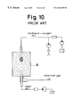
In a reforming unit using a partial oxidation reaction, heat supply from the outside is unnecessary, and for example, in the conventional hydrogen generating apparatus (Japanese Patent Unexamined Publication No. Hei. 8-231201), there is proposed a structure as shown in FIG. 10, in which a raw fuel is directly blown into a reforming unit K.
In the paper “REFORMERS FOR THE PRODUCTION OF HYDROGEN FROM METHANOL AND ALTERNATIVE FUELS FOR FUEL CELL POWERED VEHICLE” published August 1992 by Argonne National Laboratory Co. Ltd., as shown in FIG. 11, the JPL autothermal reformer is constructed such that a raw fuel gas, air, and water vapor are mixed by a swirl mixer SM, and are supplied in an axial direction of a cylindrical reforming unit in which a low temperature active catalytic layer L, an oxidation catalytic layer O, and a water vapor reforming catalytic layer H are arranged in sequence along the length of the reforming unit, so that the fed raw fuel gas is reformed.
In the above hydrogen generating apparatus, it is difficult to supply a raw fuel uniformly to the catalytic layers within the reforming unit, and so to effectively use the entirety of the catalytic layers, so that a sufficient shift reaction cannot be performed. Further, it is difficult to raise the volume velocity.
In the foregoing reformer, since the passage length of the cylindrical reforming unit through which a raw fuel gas passes is large, if a volume velocity, that is, a reaction gas flow amount per unit volume of a catalyst, which is an index of catalyst efficiency, is to be raised, the flow velocity becomes high and the pressure loss rises, so that the raw fuel must be introduced at a high pressure and high power consumption results.
Moreover, in order for the shift reaction to be sufficiently performed, the volume of the water vapor reaching the reforming catalytic layer for performing water vapor reforming reaction in FIG. 11 is required to be large, so that the pressure loss is further increased and the volume velocity is lowered.
SUMMARY OF THE INVENTION
It is an object of the present invention to enable a sufficient shift reaction by effectively using the entirety of the catalytic layer in the reformer.
It is a further object of the present invention to enable a sufficient shift reaction by raising the volume velocity in the reformer.
It is yet a further object of the present invention to enable a sufficient shift reaction by lowering the pressure loss in the reformer.
According to the present invention, the above and-other objects are achieved in a reformer for a fuel cell using a partial oxidation reaction (also called autothernal) as a reforming reaction, where the inside of a container is divided by the catalytic layer into an inlet space communicating with the inlet for introduction of a vapor of a methanol solution as a raw fuel and an outlet space communicating with the outlet for discharge of the reformed gas, and a passage cross section of the catalytic layer at the side of the outlet space is larger than a passage cross section at the side of the inlet space.
According to a first aspect of the present invention, a reformer for a fuel cell using a partial oxidation reaction as a reforming reaction comprises a container including an inlet for introduction of a vapor of a methanol solution as a raw fuel and an outlet for discharge of a reformed gas, and a catalytic layer structured such that the inside of the container is divided into an inlet space communicating with the inlet and an outlet space communicating with the outlet, in which a passage cross section of the catalytic layer at a side of the outlet space is larger than a passage cross section at a side of the inlet space.
According to a second aspect of the present invention in the first aspect, the passage cross section of the catalytic layer at the side of the outlet space is larger by a range of 20% to 250% than the passing cross section at the side of the inlet space.
According to a third aspect of the present invention in the first aspect, the passage cross section of the catalytic layer becomes gradually larger from the side of the inlet space to the side of the outlet space.
According to the fourth aspect of the present invention in the first aspect, the catalytic layer is made of a porous material hydrocarbon catalyst, such as ceramics including alumina supporting a methanol reforming catalyst.
According to a fifth aspect of the present invention in the first aspect, the catalytic layer is made up of a small diameter cylindrical wire mesh, a large diameter cylindrical wire mesh coaxially disposed with the small diameter wire mesh, and a granular catalyst disposed between the small diameter wire mesh and the large diameter wire mesh.
According to a sixth aspect of the present invention in the first aspect, the container is a hollow cylindrical container in which an opening is formed at a center of one axial end of the container and an opening is formed at a center of the other axial end, the catalytic layer is formed of a hollow cylinder with a smaller outer diameter and a shorter length in an axial direction than those of the container, one axial end of the catalyst layer is fixed to the one axial end of the container in which the one opening constituting the inlet is formed, and a plate is provided for closing a center opening of the other axial end of the catalyst layer.
According to a seventh aspect of the present invention in the first aspect, the container is a hollow cylindrical container in which an opening is formed at a peripheral portion of one axial end of the container and an opening is formed at a center of the other axial end. The catalytic layer is structured as a plurality of diametric parts of hollow cylinders are provided side by side and at equal angles on an inner peripheral wall of the container. The inlet space is formed between the inner peripheral wall of the container and an inner peripheral wall of each of the parts of the hollow cylinders and the outlet space is formed between outer peripheral walls of the parts of the hollow cylinders.
According to an eighth aspect of the present invention in the first aspect, the container is a hollow truncated cortical container in which an opening is formed at a center of one axial end of the container and an opening is formed at a center of the other axial end, and in which an outer diameter of the container increases gradually, and the catalytic layer is disposed in the truncated conical container between a position separated from the opening constituting the inlet by a fixed distance and a position separated from the opening constituting the outlet by a fixed distance.
According to a ninth aspect of the present invention in the first aspect, the container is a hollow cylindrical container in which an opening is formed at a center of one axial end of the container and an opening is formed at a center of the other axial end. The catalytic layer is disposed inside the container and is formed of a hollow sphere including a small diameter spherical inlet space. The inlet space of the hollow sphere communicates with the opening of the one axial end of the container, and the outlet space is formed between an outer wall of the catalytic layer of the hollow sphere and an inner peripheral wall of the container.
According to a tenth aspect of the present invention in the first aspect, hydrocarbon as the raw fuel is introduced into the container and is reformed.
In the reformer for a fuel cell of the first aspect of the present invention, the vapor of the methanol solution as the raw fuel is introduced into the inlet space of the container through the inlet, the vapor of the methanol solution is subjected to a partial oxidation reaction as a reforming reaction by the catalytic layer structured such that the inside of the container is divided into the inlet space and the outlet space, and the passage cross section of the catalytic layer at the side of the outlet space is larger then the passage cross section at the side of the inlet space, and a reformed gas is discharged outside of the container from the outlet, so that the entirety of the catalytic layer is effectively used and a sufficient shift reaction is made possible.
The reformer for a fuel cell of the second aspect of the present invention is structured such that in the first aspect, the passage cross section of the catalytic layer at the side of the outlet space is made larger by a range of 20% to 250% than the passage cross section at the side of the inlet space, so that even if the volume flow amount of the reformed gas is increased by the increase of the mole number in the reforming reaction, the increase of the flow velocity of the reformed gas is suppressed, and the increase of the pressure loss is suppressed so that the pressure loss is reduced.
The reformer for a fuel cell of the third aspect of the present invention is structured such that in the first aspect, the passage cross section of the catalytic layer becomes gradually larger from the side of the inlet space to the side of the outlet space, so that even if the volume flow amount of the reformed gas is increased by the increase of the mole number in the reforming reaction, the increase of the flow velocity of the reformed gas is uniformly suppressed and the increase of the pressure loss is suppressed so that the pressure loss is reduced.
The reformer for a fuel cell of the fourth aspect of the present invention is structured such that in the first aspect, the catalytic layer is made of a porous material supporting the hydrocarbon reforming catalyst, so that the vapor of the methanol solution passing through the catalytic layer is uniformly reformed by the methanol reforming catalyst supported by the porous material.
The reformer for a fuel cell of the fifth aspect of the present invention is structured such that in the first aspect, the catalytic layer is made of a small diameter cylindrical wire mesh, a large diameter cylindrical wire mesh coaxially disposed with the small diameter wire mesh and a granular catalyst disposed between the small diameter wire mesh and the large diameter wire mesh, so that the vapor of the methanol solution passing through the catalytic layer is uniformly reformed by the granular catalyst.
The reformer for a fuel cell of the sixth aspect of the present invention is structured such that in the first aspect, the vapor of the methanol solution as the raw fuel is introduced through the opening formed at the center of one axial end of the hollow cylindrical container into the inlet space formed inside the catalytic layer of the hollow cylinder which is fixed to the one axial end of the hollow cylindrical container and has a small outer diameter and the short. length in an axial direction. The vapor of the methanol solution is subjected to a partial oxidation reaction as the reforming reaction by the catalytic layer of the hollow cylinder, and the reformed gas is discharged from the opening formed at the center of the other axial end of the container through the outlet space at the outer peripheral side of the catalytic layer of the hollow cylinder and at the outside of the plate disposed at the center opening of the other axial end of the hollow cylinder and closing the opening so that the entirety of the catalytic layer is effectively used, a sufficient shift reaction is made possible, the volume velocity is raised, and the pressure loss is reduced.
The reformer for a fuel cell of the seventh aspect of the present invention is structured such that in the first aspect, the vapor of the methanol solution as the raw fuel is introduced through the opening formed at the peripheral portion of the one axial end of the hollow cylindrical container into the inlet space formed between the inner peripheral wall of the container and each of the catalytic layers made of the diametric parts of hollow cylinders, and which are provided side by side and at equal angles on the inner peripheral wall of the container. The introduced vapor of the methanol solution is subjected to a partial oxidation reaction as a reforming reaction by the catalytic layers, and the reformed gas is discharged from the opening formed at the center of the other axial end of the container through the outlet space formed between the outer peripheral walls of the respective catalytic layers, so that the entirety of the catalytic layer is effectively used, a sufficient shift reaction is made possible, the volume velocity is raised and the pressure loss is reduced.
The reformer for a fuel cell of the eighth aspect of the present invention is structured such that in the first aspect, the vapor of the methanol solution as the raw fuel is introduced through the opening formed at the center of one axial end of the hollow truncated conical container with a gradually increasing outer diameter into the inlet space formed between the opening and the catalytic layer disposed at a position separate from the opening by a fixed distance. The introduced vapor of the methanol solution is subjected to a partial oxidation reaction as the reforming reaction by the truncated conical catalytic layer, and the reformed gas is discharged from the opening formed at the center of the other axial end of the container through the outlet space formed between the catalytic layer and the other axial end of the container, so that the entirety of the catalytic layer is effectively used, a sufficient shift reaction is made possible, the volume velocity is raised and the pressure loss is reduced.
The reformer for a fuel cell of the ninth aspect of the present invention is structured such that in the first aspect, the vapor of the methanol solution as the raw fuel is introduced through the opening formed at the center of one axial end of the hollow cylindrical container into the spherical inlet space with a small diameter formed inside the catalytic layer of the hollow sphere, the introduced vapor of the methanol solution is subjected to a partial oxidation reaction as the reforming reaction by the catalytic layer of the hollow sphere, and the reformed gas is discharged from the opening formed at the center of the other axial end of the container through the outlet space formed between the catalytic layer and the inner peripheral wall of the container, so that the entirety of the catalytic layer is effectively used, a sufficient shift reaction is made possible, the volume velocity is raised, and the pressure loss is reduced.
The reformer for a fuel cell of the tenth aspect of the present invention is structured such that in the first aspect, hydrocarbon as the raw fuel is introduced into the container and is reformed by the catalytic layer, so that even if the volume flow amount of the reformed gas is increased by the increase of the mole number in the reforming reaction, the increase of the flow velocity of the reformed gas is uniformly suppressed and the increase of the pressure loss is suppressed.
BRIEF DESCRIPTION OF THE DRAWINGS
FIG. 1 is a sectional view showing a reformer for a fuel cell of a first embodiment of the present invention.
FIG. 2 is a block diagram showing the entirety of the reformer for a fuel cell of the first embodiment.
FIG. 3 is a partial enlarged sectional view showing a catalytic layer in the first embodiment.
FIG. 4 is a sectional view showing a reformer for a fuel cell of a second embodiment of the present invention.
FIG. 5 is a sectional view showing the cross section of a container of the second embodiment.
FIG. 6 is a sectional view showing a reformer for a fuel cell of a third embodiment of the present invention.
FIG. 7 is a plan view showing a container of the third embodiment.
FIG. 8 is a sectional view showing a reformer for a fuel cell of a fourth embodiment of the present invention.
FIG. 9 is a plan view showing a container of the fourth embodiment.
FIG. 10 is a sectional view showing a conventional hydrogen generating apparatus.
FIG. 11 is a sectional view showing a conventional reformer.
DESCRIPTION OF THE PREFERRED EMBODIMENTS
Preferred embodiments of the present invention will be described below with reference to the drawings.
(First Embodiment)
As shown in FIGS. 1 to 3, a reformer for a fuel cell of a first embodiment includes a hollow cylindrical container 30 having an opening which is formed at a center of one axial end of the container and functions as an inlet 31 for introduction of a vapor of a methanol solution as a raw fuel, and an opening which is formed at a center of the other axial end and functions as an outlet 32 for discharge of a reformed gas. A catalytic layer 7 made as a hollow cylinder 70 having a smaller outer diameter and a shorter length in an axial direction than those of the container is positioned coaxially within the hollow cylindrical container 30. The catalytic layer is structured such that one axial end of the hollow cylinder is fixed to the one axial end of the container 30. A plate 8 is disposed to close a center opening at the downstream axial end of the hollow cylinder. A partial oxidation reaction as a reforming reaction takes place in the catalytic layer. An inlet space 71, which may be cylindrical, is formed within the hollow of the hollow cylindrical catalytic layer and communicates with the inlet, and an annular outlet space 72 is formed outside of the catalytic layer of the hollow cylinder and communicates with the outlet.
The raw fuel gas to be reformed enters the container 30 via the inlet 31 to reach the inlet space 71. From there it passes through the catalytic layer 7, to be reformed, and reaches the annular outlet space 72. Since the inlet space is positioned radially inside of the catalytic layer 7 and the outlet space is positioned radially outside of the catalytic layer 7, the gas passage cross section of the catalytic layer at the side of the outlet space is larger than the gas passage cross section at the side of the inlet space.
As shown in FIG. 2, the reformer for a fuel cell of the first embodiment includes a methanol solution tank 1 for storing the methanol solution as the raw fuel, a vaporizer 2 for vaporizing the methanol solution supplied from the methanol solution tank 1, and a blower 4 for mixing air to the methanol vapor and water vapor supplied from the vaporizer 2 and for supplying the mixture to a reforming unit 3.
As shown in FIG. 1, in the hollow cylindrical container 30, an opening is formed at the center of the one axial end of the container, and a small diameter pipe forming the inlet 31 for introduction of the vapor of the methanol solution as a raw fuel is coaxially disposed with the opening. Moreover, another opening is formed at the center of the other axial end of the container and a small diameter pipe forming the outlet 32 for discharge of the reformed gas is coaxially disposed with the other opening.
Referring to FIG. 1, the catalytic layer 7 is formed from a cylindrical wire mesh 6 with a small diameter, a cylindrical wire mesh 5 with a large diameter disposed coaxially around the cylindrical wire mesh 6 with a small diameter, and granular catalyst disposed between them. A partial oxidation reaction is performed as the reforming reaction.
The hollow cylinder 70 has a smaller outer diameter and a shorter length in an axial direction than the container 30. One axial end of the hollow cylinder 70 is fixed to one axial end of the container and the plate 8 is disposed to close the center opening of the other axial end of the hollow cylinder.
As shown in FIG. 3, the gas passage cross section of the catalytic layer 7 at the side of the outlet space is larger than a passage cross section at the side of the inlet space by a range of 20% to 250%. Since the gas flows generally radially through the catalytic layer 7, this increased passage cross section is exemplified by the divergence from spacing A to spacing B of the radial lines shown in this figure. Since the catalytic layer 7 is formed in a hollow cylinder 70, as shown in FIG. 3, the passage cross section increases gradually from the inlet space side to the outlet space side.
In the reformer for a fuel cell of the first embodiment having the above structure, the vapor of the methanol solution is sent from the methanol solution tank 1 (FIG. 2) to the vaporizer 2, and the methanol vapor vaporized into a gas and water vapor are sent to the reforming unit 3. At that time, air for the reforming reaction is supplied from the blower 4 into the vaporized methanol vapor and the water vapor from the vaporizer 2. Thereafter, the supplied methanol vapor, water vapor, and air are reformed by the reforming unit 3, and discharged from the outlet 32 as a gas rich in hydrogen.
Within the reforming unit 3, the methanol vapor as the raw fuel, water vapor, and air are introduced through the raw fuel inlet 31 and reach the granular catalytic layer 7 via the inlet space and the catalyst holding mesh 6, so that a reforming reaction is started. Thereafter, the raw fuel reformed by the catalytic layer 7 passes as a reformed gas through the catalyst holding mesh 5 and is discharged via the outlet space 72 from the reformed gas outlet 32.
In the above reforming process, raw fuel having passed through a portion A of the catalyst holding mesh 6 (FIG. 3) is reformed within the catalytic layer 7 a cross section which gradually increases. Generally, in a reforming reaction, the total mole number of produced materials is larger than the total mole number of raw fuel materials in a vapor state, and so the volume flow amount of the produced materials is larger than that of the raw fuel materials. If, as in the conventional apparatus, the passage cross section of the catalytic layer is constant, the flow velocity becomes high so that the pressure loss is increased. Especially in the shift reaction in which the reaction is comparatively slow, if the flow velocity is increased in order to produce a sufficient reaction, the thickness of the catalytic layer in the passage direction must be increased, which further increases the pressure loss, and more power for introducing the raw fuel becomes necessary so that the total efficiency is lowered.
However, in the first embodiment, as shown in FIG. 3, since the passage cross section of the catalytic layer 7 is gradually increased, the increase of the flow velocity can be suppressed, and the increase of the pressure loss can be suppressed. In this way, the reformed gas produced by the reforming reaction in the catalytic layer 7 passes through the catalyst holding mesh 5 and is discharged through the outlet space 72 from the gas discharge outlet 32.
In the reformer for a fuel cell of the first embodiment having the above operation, the vapor of the methanol solution as the raw fuel is subjected to a partial oxidation reaction and water vapor reactions as the reforming reaction by the catalytic layer 7. The passage cross section at the side of the outlet space is larger than the passage cross section at the side of the inlet space and the reformed gas is discharged outside of the container 30 from the outlet 32, so that the entirety of the catalytic layer 7 is effectively used and a sufficient shift reaction is made possible.
Moreover, in the reformer for a fuel cell of the first embodiment, the passage cross section of the catalytic layer 7 at the side of the outlet space is larger by a range of 20% to 250% than the passage cross section at the side of the inlet space, so that even if the volume flow amount of the reformed gas is increased by an increased mole number in the reforming reaction, the increase of the flow velocity of the reformed gas is suppressed and the increase of a pressure loss is suppressed, so that the pressure loss is reduced. Moreover, in the reformer for a fuel cell of the first embodiment, the catalytic layer 7 is a hollow cylinder and the passage cross section of the catalytic layer becomes gradually larger from the side of the inlet space 71 to the side of the outlet space 72, so that even if the volume flow amount of the reformed gas is increased by the increase of the mole number in the reforming reaction, the increase of the flow velocity of the reformed gas is uniformly suppressed and the increase of a pressure loss is suppressed, so that the pressure loss is reduced.
Moreover, in the reformer for a fuel cell of the first embodiment, the catalytic layer 7 is made up of the small diameter cylindrical wire mesh 6, the large diameter cylindrical wire mesh 5 coaxially disposed with the small diameter wire mesh, and the granular catalyst disposed between the small diameter cylindrical wire mesh 6 and the large diameter cylindrical wire mesh 5, so that the vapor of the methanol solution passage through the catalytic layer is uniformly reformed by the granular catalyst.
Moreover, in the reformer for a fuel cell of the first embodiment, the vapor of the methanol solution is subjected to a partial oxidation reaction and the water vapor reforming reaction as the reforming reaction by the catalytic layer 7 of the hollow cylinder 70, and the reformed gas is discharged from the outlet 32 formed at the center of the other axial end of the container 30 through the outlet space 72 at the outer peripheral side of the catalytic layer 7 and outside of the plate 8 disposed at the center opening of the downstream axial end of the hollow cylinder and closing the opening, so that the entirety of the catalytic layer 7 is effectively used, a sufficient shift reaction is made possible, the volume velocity is raised and the pressure loss is reduced.
(Second Embodiment)
As shown in FIGS. 4 and 5, a reformer for a fuel cell of a second embodiment is different from the first embodiment in that a plurality of catalytic layers 73 are disposed in a container 30, inlet spaces 71 are formed between the container 30 and the plurality of catalytic layers 73, and an outlet space 72 is formed outside of the plurality of catalytic layers 73.
In the reformer for a fuel cell of the second embodiment, the container 30 is formed as a hollow cylindrical container having a plurality of inlets 31 at the periphery of one axial end of the container end an outlet 32 formed at a center of the other axial end. The catalytic layer is made up of a plurality of diametric sections or parts 73 of hollow cylinders which are provided side by side on the inner peripheral wall of the container 30 at equal angles.
For each of the parts of the hollow cylinders making up the respective catalytic layers 73, a cylindrical wire mesh 62 with a small diameter and a cylindrical wire mesh 53 with a large diameter are coaxially disposed, and a granular catalyst is disposed between them to form the hollow cylinder. A partial oxidation reaction and a water vapor reforming reaction are performed as the reforming reaction.
In the reformer for a fuel cell of the second embodiment having the above structure, the vapor of the methanol solution as the raw fuel and air are introduced from the plurality of inlets 31 formed at the peripheral portion of the one axial end of the hollow cylindrical container 30 into the inlet spaces 71 formed between the inner peripheral wall of the container and of the plurality of catalytic layers 73. The vapor of the methanol solution and air introduced through the catalytic layers 73 is subjected to partial oxidation reaction as the reforming reaction. The resulting reformed gas is discharged from the outlet 32 formed at the center of the other axial end of the container 30 through the outlet space 72 formed between the outer peripheral walls of the respective catalytic layers 73.
In the reformer for a fuel cell of the second embodiment having the above operation, the passage cross section of the catalytic layer at the exit side is larger than the passage cross section at the entrance side, so that the entirety of the catalytic layer 73 is effectively used, a sufficient shift reaction is made possible, the volume velocity is raised, and the pressure loss is reduced even if the volume of the reformed gas is increased by an increase of the mole number during the reforming reaction.
(Third Embodiment)
A reformer for a fuel cell of a third embodiment is different from the first embodiment in that, as shown in FIGS. 6 and 7, a catalytic layer 74 is disposed at a center of a hollow truncated conical container 33 having vertically spaced inlet and outlet spaces. The container 33 is a hollow truncated conical container in which an inlet 31 is formed at a center of one axial end of the container and an outlet 32 is formed at a center of the other axial end, and the outer diameter of which is gradually increased.
For the catalytic layer 74, circular wire meshes as catalyst holding meshes are respectively disposed in the truncated conical container 33 at a position separate from the opening constituting the inlet 31 by a constant distance and at a position separate from the opening constituting the outlet 32 by a constant distance, and a granular catalyst is interposed between the meshes. A first space 75 is formed between the one axial end of the truncated conical container 33 at the side of the inlet 31 and the upper end of the truncated conical catalytic layer 74, and a second space 76 is formed between the other axial end of the truncated conical container 33 and the lower end of the truncated conical catalytic layer 74.
In the reformer for a fuel cell of the third embodiment having the above structure, the vapor of the methanol solution as the raw fuel and air are introduced from the inlet 31 into the inlet space 75 formed between the inlet 31 and the upper end of the catalytic layer 74. The introduced vapor of the methanol solution and air are subjected to a partial oxidation reaction as the reforming reaction in the truncated conical catalytic layer 74, and the reformed gas is discharged through the outlet space 76 formed between the catalytic layer 74 and the other axial end of the container 33.
In the reformer for a fuel cell of the third embodiment having the above operation, since the introduced vapor of the methanol solution and air are subjected to a partial oxidation reaction as the reforming reaction by the truncated conical catalytic layer 74 with a gradually increasing passage cross section, the entirety of the catalytic layer is effectively used, a sufficient shift reaction is made possible, the volume velocity is raised, and the pressure loss is reduced.
Since the reformer for a fuel cell of the third embodiment having the above operation is formed as a simple structure in which the catalytic layer 74 is disposed at the center of the hollow truncated conical container 33 to provide the spaces 75 and 76, the cost is reduced and maintenance becomes easy.
(Fourth Embodiment)
A reformer for a fuel cell of a fourth embodiment is of different from the first embodiment in that, as shown in FIGS. 8 and 9, a spherical catalytic layer 77 is disposed at the center of a hollow cylindrical container 30, and inlet and outlet spaces 78 and 79 are formed inside and outside the spherical catalytic layer 77. The container 30 is formed as a hollow cylindrical container in which an opening and an inlet 31 are formed at the center of one axial end of the container, and an opening and an outlet 32 are formed at the center of the other axial end.
The catalytic layer 77 is formed as a hollow sphere disposed in the container 30 and having a spherical inlet space 78 with a small diameter. The inlet space 78 of the catalytic layer 77 of the hollow sphere communicates with the opening of the one axial end of the container 30, end the outlet space 79 is formed between the outer wall of the catalytic layer 77 of the hollow sphere and the inner peripheral wall of the container 30. The catalytic layer 77 is made of a porous material supporting a methanol reforming catalyst, such as ceramics including alumina.
In the reformer for a fuel cell of the fourth embodiment having the above structure, the vapor of the methanol solution as the raw fuel and air are introduced from the inlet 31 into the spherical inlet space 78 with the small diameter formed inside the catalytic layer 77 of the hollow sphere. The introduced vapor of the methanol solution and air are subjected to a partial oxidation reaction as the reforming reaction in the catalytic layer 77 of the hollow sphere, and the reformed gas is discharged through the outlet space 79.
In the reformer for a fuel cell of the fourth embodiment having the above operation, since the introduced vapor of the methanol solution and air are subjected to a partial oxidation reaction as the reforming reaction by the catalytic layer 77 of the hollow sphere, the catalytic layer is effectively used, a sufficient shift reaction is made possible, the volume velocity is raised, and the pressure loss is reduced. That is, since the partial oxidation reaction is performed by the catalytic layer 77 as a hollow sphere in which the passage cross section of the catalytic layer increases from the inner peripheral side to the outer peripheral side three dimensionally, the increase of the flow velocity can be suppressed and the increase of the pressure loss can be suppressed.
If, as in the conventional apparatus, if the passage cross section of the catalytic layer is constant, the flow velocity becomes high so that the pressure loss is increased. Especially in the shift reaction in which the reaction is comparatively slow, if the flow velocity is increased in order to produce a sufficient reaction, the thickness of the catalytic layer in the passage direction must be increased, which further increases the pressure loss and more power for introducing the raw fuel becomes necessary, so that the total efficiency is lowered. This problem can be solved by the reformer of the present invention.
Moreover, in the reformer for a fuel cell of the fourth embodiment, since the catalytic layer 77 is made of a porous material supporting the methanol reforming catalyst, such as ceramics including alumina, the vapor of the methanol solution passing through the catalytic layer is uniformly reformed by the methanol reforming catalyst supported by the porous material, the number of components is reduced and the structure is made simple.
The foregoing embodiments are shown for explanation, and the present invention is not limited to those, but may be modified or may be added to with any feature, as long as the modification or addition is not inconsistent with the technical concept of the present invention recognized from the claims, the section of the detailed description of the invention, and the drawings.
In the foregoing first to third embodiments, although a granular catalyst is interposed between the wire meshes has been explained as an example, the present invention is not limited thereto, but a mode in which a catalytic layer is formed of a porous material supporting a catalyst may be adopted.
In the foregoing fourth embodiment, although the catalytic layer is formed of a porous material supporting the catalyst has been explained as an example, the present invention is not limited thereto, but a mode in which a catalytic layer is formed of a granular catalyst interposed between spherical wire meshes may be adopted.

Claims (9)

What is claimed is:
1. A reformer for a fuel cell using a partial oxidation reaction as a reforming reaction for producing hydrogen, comprising:
a container including an inlet for introduction of a vapor of a methanol solution as a raw fuel and an outlet for discharge of a reformed gas; and
a catalytic layer in said container and structured such that the inside of the container is divided into an inlet space communicating with the inlet and an outlet space communicating with the outlet, and such that a passage cross section of the catalytic layer at a side of the outlet space is larger than a passage cross section at a side of the inlet space, wherein said catalytic layer is made of a porous material supporting a hydrocarbon reforming catalyst.
2. The reformer for a fuel cell as claimed in claim 1, wherein the passage cross section of the catalytic layer at the side of the outlet space is larger by 20% to 250% than the passage cross section at the side of the inlet space.
3. The reformer for a fuel cell as claimed in claim 1, wherein the passage cross section of the catalytic layer gradually increases from the side of the inlet space to the side of the outlet space.
4. The reformer for a fuel cell as claimed in claim 1, wherein:
the container comprises a hollow cylinder having an opening at a center of one axial end of the container and an opening at a center of the other axial end of the container; and
the catalytic layer includes a hollow cylinder with a smaller outer diameter and a shorter length in an axial direction than those of the container, one axial end of the catalytic layer being fixed to the one axial end of the container in which the inlet is disposed, the reformer further comprising a plate for closing the hollow of the catalytic layer at the other axial end of the container.
5. The reformer for a fuel cell as claimed in claim 1, wherein:
the container is a hollow cylindrical container having an opening at a peripheral portion of one axial end of the container and an opening at a center of the other axial end;
the catalytic layer includes a plurality of diametric parts of hollow cylinders provided side by side at equal angles on an inner peripheral wall of the container; and
the inlet space is formed between the inner peripheral wall of the container and an inner peripheral wall of each of the diametric parts of the hollow cylinders, and the outlet space is formed between outer peripheral walls of the diametric parts of the hollow cylinders.
6. The reformer for a fuel cell as claimed in claim 1, wherein:
the container is a hollow truncated conical container having an inlet opening at a center of one axial end of the container and an outlet opening at a center of the other axial end of the container, an outer diameter of the container increasing gradually from the one of said axial ends to the other; and
the catalytic layer is disposed in the truncated conical container between a position separate by a fixed distance from the inlet opening and a position separate by a fixed distance from the outlet opening.
7. The reformer for a fuel cell as claimed in claim 1, wherein:
the container is a hollow cylindrical container having an opening at a center of one axial end of the container and an opening at a center of the other axial end of the container;
the catalytic layer is disposed inside the container and includes a hollow sphere having an inlet space extending therein and communicating with the opening of the one axial end of the container; and
the outlet space is disposed between an outer wall of the catalytic layer of the hollow sphere and an inner peripheral wall of the container.
8. The reformer for a fuel cell as recited in claim 1, wherein the catalytic layer is made of ceramics including alumina.
9. A reformer for a fuel cell using a partial oxidation reaction as a reforming reaction for producing hydrogen, comprising:
a container including an inlet for introduction of a hydrocarbon and water as a raw fuel and an outlet for discharge of a reformed gas; and
a catalytic layer in said container and structured such that the inside of the container is divided into an inlet space communicating with the inlet and an outlet space communicating with the outlet, and such that a passage cross section of the catalytic layer at a side of the outlet space is larger than a passage cross section at a side of the inlet space, wherein said catalytic layer is made of a porous material supporting a hydrocarbon reforming catalyst.
US09/185,504 1997-11-04 1998-11-04 Reformer for a fuel cell Expired - Fee Related US6284398B1 (en)

Applications Claiming Priority (2)

Application Number Priority Date Filing Date Title
JP9-319041 1997-11-04
JP9319041A JPH11139802A (en) 1997-11-04 1997-11-04 Reformer for fuel cell

Publications (1)

Publication Number Publication Date
US6284398B1 true US6284398B1 (en) 2001-09-04

Family

ID=18105863

Family Applications (1)

Application Number Title Priority Date Filing Date
US09/185,504 Expired - Fee Related US6284398B1 (en) 1997-11-04 1998-11-04 Reformer for a fuel cell

Country Status (3)

Country Link
US (1) US6284398B1 (en)
JP (1) JPH11139802A (en)
DE (1) DE19850864A1 (en)

Cited By (34)

* Cited by examiner, † Cited by third party
Publication number Priority date Publication date Assignee Title
US20020131921A1 (en) * 2001-03-15 2002-09-19 Aisin Seiki Kabushiki Kaisha Fuel reformer for use in fuel cell
US20020141924A1 (en) * 2001-03-19 2002-10-03 Aisin Seiki Kabushiki Kaisha Co-shift device
US6536546B2 (en) * 2000-03-14 2003-03-25 Ballard Power Systems Ag Method for shortening the starting time of CO oxidation catalytic converters in mobile fuel cell systems
US6565817B1 (en) 1997-09-04 2003-05-20 Aisin Seiki Kabushiki Kaisha Reformer for a fuel cell
US6632409B1 (en) 1998-12-21 2003-10-14 Aisin Seiki Kabushiki Kaisha Reformer for fuel cell system
US20040101471A1 (en) * 2002-11-26 2004-05-27 Petch Michael Lan Methods, apparatus, and systems for producing hydrogen from a fuel
US20040136903A1 (en) * 2001-06-06 2004-07-15 Peter Hinton Furnace and steam reforming process
US20040231616A1 (en) * 2003-05-21 2004-11-25 Ellis Suzanne Rose Fuel reforming system and method of operation
US6833209B2 (en) 2001-03-23 2004-12-21 Aisin Seiki Kabushiki Kaisha Fuel-cell co-generation system, of electrical energy and hot water
US20060099117A1 (en) * 2003-07-26 2006-05-11 Agnew Gerard D Reformer module
US20060233700A1 (en) * 2005-04-18 2006-10-19 Anand Chellappa Compact devices for generating pure hydrogen
US20060280662A1 (en) * 2005-06-10 2006-12-14 Samsung Electro-Mechanics Co., Ltd. Micro reformer and micro fuel cell having the same
US7156887B1 (en) 2002-11-26 2007-01-02 General Motors Corporation Methods, apparatus, and systems for producing hydrogen from a fuel
US20070151154A1 (en) * 2005-11-04 2007-07-05 Maxim Lyubovsky Catalytic system for converting liquid fuels into syngas
WO2008073080A1 (en) * 2006-12-11 2008-06-19 Utc Fuel Cells, Llc Method for operating a membrane electrode assembly to mitigate membrane decay
US7459224B1 (en) 2002-11-26 2008-12-02 General Motors Corporation Methods, apparatus, and systems for producing hydrogen from a fuel
US20090252661A1 (en) * 2008-04-07 2009-10-08 Subir Roychoudhury Fuel reformer
US20090275104A1 (en) * 2004-01-09 2009-11-05 Novozymes A/S Bacillus licheniformis chromosone
US20090293358A1 (en) * 2005-11-04 2009-12-03 Subir Roychoudhury Catalytic system for converting liquid fuels into syngas
US20100300930A1 (en) * 2009-03-13 2010-12-02 Exxonmobil Research And Engineering Company Process for making high octane gasoline with reduced benzene content by benzene alkylation at high benzene conversion
US7867300B2 (en) 2001-03-02 2011-01-11 Intelligent Energy, Inc. Ammonia-based hydrogen generation apparatus and method for using same
US7875089B2 (en) 2001-03-02 2011-01-25 Intelligent Energy, Inc. Ammonia-based hydrogen generation apparatus and method for using same
US20110061299A1 (en) * 2005-11-04 2011-03-17 Subir Roychoudhury Catalytic process and system for converting liquid fuels into syngas
US7922781B2 (en) 2001-03-02 2011-04-12 Chellappa Anand S Hydrogen generation apparatus and method for using same
WO2011116157A1 (en) * 2010-03-17 2011-09-22 Dow Technology Investments Llc Catalytic fixed bed reactor for producing ethylene oxide by partial oxidation of ethylene
US8172913B2 (en) 2002-04-23 2012-05-08 Vencill Thomas R Array of planar membrane modules for producing hydrogen
US8337757B2 (en) 2008-02-07 2012-12-25 Precision Combustion, Inc. Reactor control method
US8795398B2 (en) 2003-07-31 2014-08-05 Precision Combustion, Inc. Apparatus for vaporizing and reforming liquid fuels
US9624104B2 (en) 2013-11-06 2017-04-18 Watt Fuel Cell Corp. Liquid fuel CPOX reformers and methods of CPOX reforming
US9627701B2 (en) 2013-11-06 2017-04-18 Watt Fuel Cell Corp. Integrated gaseous fuel CPOX reformer and fuel cell systems, and methods of producing electricity
US9627700B2 (en) 2013-11-06 2017-04-18 Watt Fuel Cell Corp. Liquid fuel CPOX reformer and fuel cell systems, and methods of producing electricity
US9627699B2 (en) 2013-11-06 2017-04-18 Watt Fuel Cell Corp. Gaseous fuel CPOX reformers and methods of CPOX reforming
US10106406B2 (en) 2013-11-06 2018-10-23 Watt Fuel Cell Corp. Chemical reactor with manifold for management of a flow of gaseous reaction medium thereto
US10676354B2 (en) 2013-11-06 2020-06-09 Watt Fuel Cell Corp. Reformer with perovskite as structural component thereof

Families Citing this family (4)

* Cited by examiner, † Cited by third party
Publication number Priority date Publication date Assignee Title
WO2001019727A1 (en) * 1999-09-10 2001-03-22 Daikin Industries, Ltd. Apparatus for producing hydrogen gas and fuel cell system using the same
DE19947312A1 (en) * 1999-10-01 2001-04-05 Volkswagen Ag Fuel reformers and reforming processes
JP4122767B2 (en) * 2001-12-20 2008-07-23 ダイキン工業株式会社 Reformer
JP4204786B2 (en) * 2002-01-11 2009-01-07 本田技研工業株式会社 Catalytic reactor

Citations (5)

* Cited by examiner, † Cited by third party
Publication number Priority date Publication date Assignee Title
US2634194A (en) * 1951-10-31 1953-04-07 Universal Oil Prod Co Lined reactor
US2884372A (en) * 1956-05-29 1959-04-28 Socony Mobil Oil Co Inc Spherical reactor for the conversion of hydrocarbons
US4814147A (en) * 1985-11-27 1989-03-21 Laboratories Flork, S.A. Column for physical or chemical treatment in heterogeneous phase
US5565178A (en) * 1993-03-03 1996-10-15 Degesch America, Inc. Method and apparatus for removing fumigation gases from fumigated structures
US5762658A (en) 1994-06-24 1998-06-09 Johnson Matthey Public Limited Company Self-sustaining hydrogene generator

Patent Citations (5)

* Cited by examiner, † Cited by third party
Publication number Priority date Publication date Assignee Title
US2634194A (en) * 1951-10-31 1953-04-07 Universal Oil Prod Co Lined reactor
US2884372A (en) * 1956-05-29 1959-04-28 Socony Mobil Oil Co Inc Spherical reactor for the conversion of hydrocarbons
US4814147A (en) * 1985-11-27 1989-03-21 Laboratories Flork, S.A. Column for physical or chemical treatment in heterogeneous phase
US5565178A (en) * 1993-03-03 1996-10-15 Degesch America, Inc. Method and apparatus for removing fumigation gases from fumigated structures
US5762658A (en) 1994-06-24 1998-06-09 Johnson Matthey Public Limited Company Self-sustaining hydrogene generator

Cited By (56)

* Cited by examiner, † Cited by third party
Publication number Priority date Publication date Assignee Title
US6565817B1 (en) 1997-09-04 2003-05-20 Aisin Seiki Kabushiki Kaisha Reformer for a fuel cell
US6632409B1 (en) 1998-12-21 2003-10-14 Aisin Seiki Kabushiki Kaisha Reformer for fuel cell system
US6536546B2 (en) * 2000-03-14 2003-03-25 Ballard Power Systems Ag Method for shortening the starting time of CO oxidation catalytic converters in mobile fuel cell systems
US7875089B2 (en) 2001-03-02 2011-01-25 Intelligent Energy, Inc. Ammonia-based hydrogen generation apparatus and method for using same
US7867300B2 (en) 2001-03-02 2011-01-11 Intelligent Energy, Inc. Ammonia-based hydrogen generation apparatus and method for using same
US7922781B2 (en) 2001-03-02 2011-04-12 Chellappa Anand S Hydrogen generation apparatus and method for using same
US20020131921A1 (en) * 2001-03-15 2002-09-19 Aisin Seiki Kabushiki Kaisha Fuel reformer for use in fuel cell
US6998096B2 (en) 2001-03-15 2006-02-14 Aisin Seiki Kabushiki Kaisha Fuel reformer for use in fuel cell
US20020141924A1 (en) * 2001-03-19 2002-10-03 Aisin Seiki Kabushiki Kaisha Co-shift device
US6805850B2 (en) 2001-03-19 2004-10-19 Aisin Seiki Kabushki Kaisha Co-shift device
US6833209B2 (en) 2001-03-23 2004-12-21 Aisin Seiki Kabushiki Kaisha Fuel-cell co-generation system, of electrical energy and hot water
US20040136903A1 (en) * 2001-06-06 2004-07-15 Peter Hinton Furnace and steam reforming process
US7067107B2 (en) * 2001-06-06 2006-06-27 Davy Process Technology Limited Furnace and steam reforming process
AU2002310608B2 (en) * 2001-06-06 2006-10-19 Davy Process Technology Limited Furnace and steam reforming process
US8172913B2 (en) 2002-04-23 2012-05-08 Vencill Thomas R Array of planar membrane modules for producing hydrogen
US20040101471A1 (en) * 2002-11-26 2004-05-27 Petch Michael Lan Methods, apparatus, and systems for producing hydrogen from a fuel
US20050172555A1 (en) * 2002-11-26 2005-08-11 Petch Michael I. Methods, apparatus, and systems for producing hydrogen from a fuel
US7156887B1 (en) 2002-11-26 2007-01-02 General Motors Corporation Methods, apparatus, and systems for producing hydrogen from a fuel
US7867299B2 (en) 2002-11-26 2011-01-11 GM Global Technology Operations LLC Methods, apparatus, and systems for producing hydrogen from a fuel
US7459224B1 (en) 2002-11-26 2008-12-02 General Motors Corporation Methods, apparatus, and systems for producing hydrogen from a fuel
US7153334B2 (en) 2003-05-21 2006-12-26 General Motors Corporation Fuel reforming system and method of operation
US20040231616A1 (en) * 2003-05-21 2004-11-25 Ellis Suzanne Rose Fuel reforming system and method of operation
US7749465B2 (en) 2003-07-26 2010-07-06 Rolls-Royce Plc Reformer module
US20100135872A1 (en) * 2003-07-26 2010-06-03 Gerard D Agnew Reformer module
US20060099117A1 (en) * 2003-07-26 2006-05-11 Agnew Gerard D Reformer module
US8043576B2 (en) 2003-07-26 2011-10-25 Rolls-Royce Plc Reformer module
US8795398B2 (en) 2003-07-31 2014-08-05 Precision Combustion, Inc. Apparatus for vaporizing and reforming liquid fuels
US20090275104A1 (en) * 2004-01-09 2009-11-05 Novozymes A/S Bacillus licheniformis chromosone
US7527661B2 (en) 2005-04-18 2009-05-05 Intelligent Energy, Inc. Compact devices for generating pure hydrogen
US20060233700A1 (en) * 2005-04-18 2006-10-19 Anand Chellappa Compact devices for generating pure hydrogen
US20060280662A1 (en) * 2005-06-10 2006-12-14 Samsung Electro-Mechanics Co., Ltd. Micro reformer and micro fuel cell having the same
US8444951B2 (en) 2005-11-04 2013-05-21 Precision Combustion, Inc. Catalytic process and system for converting liquid fuels into syngas
US8557189B2 (en) 2005-11-04 2013-10-15 Precision Combustion, Inc. Catalytic system for converting liquid fuels into syngas
US20070151154A1 (en) * 2005-11-04 2007-07-05 Maxim Lyubovsky Catalytic system for converting liquid fuels into syngas
US20110061299A1 (en) * 2005-11-04 2011-03-17 Subir Roychoudhury Catalytic process and system for converting liquid fuels into syngas
US20090293358A1 (en) * 2005-11-04 2009-12-03 Subir Roychoudhury Catalytic system for converting liquid fuels into syngas
WO2008073080A1 (en) * 2006-12-11 2008-06-19 Utc Fuel Cells, Llc Method for operating a membrane electrode assembly to mitigate membrane decay
US8337757B2 (en) 2008-02-07 2012-12-25 Precision Combustion, Inc. Reactor control method
US9102531B2 (en) 2008-02-07 2015-08-11 Precision Combustion, Inc. Reactor control method
US20090252661A1 (en) * 2008-04-07 2009-10-08 Subir Roychoudhury Fuel reformer
US8395006B2 (en) 2009-03-13 2013-03-12 Exxonmobil Research And Engineering Company Process for making high octane gasoline with reduced benzene content by benzene alkylation at high benzene conversion
US20100300930A1 (en) * 2009-03-13 2010-12-02 Exxonmobil Research And Engineering Company Process for making high octane gasoline with reduced benzene content by benzene alkylation at high benzene conversion
US10010856B2 (en) 2010-03-17 2018-07-03 Dow Technology Investments Llc Efficient fixed bed platform for production of ethylene oxide by partial oxidation of ethylene using catalyst of wide selectivity
US9073034B2 (en) 2010-03-17 2015-07-07 Dow Technology Investments Llc Efficient fixed bed platform for production of ethylene oxide by partial oxidation of ethylene using catalyst of wide selectivity
WO2011116157A1 (en) * 2010-03-17 2011-09-22 Dow Technology Investments Llc Catalytic fixed bed reactor for producing ethylene oxide by partial oxidation of ethylene
US9624104B2 (en) 2013-11-06 2017-04-18 Watt Fuel Cell Corp. Liquid fuel CPOX reformers and methods of CPOX reforming
US9627700B2 (en) 2013-11-06 2017-04-18 Watt Fuel Cell Corp. Liquid fuel CPOX reformer and fuel cell systems, and methods of producing electricity
US9627699B2 (en) 2013-11-06 2017-04-18 Watt Fuel Cell Corp. Gaseous fuel CPOX reformers and methods of CPOX reforming
US9878908B2 (en) 2013-11-06 2018-01-30 Watt Agent, Llc Liquid fuel reformer including a vaporizer and method of reforming liquid reformable fuel
US9627701B2 (en) 2013-11-06 2017-04-18 Watt Fuel Cell Corp. Integrated gaseous fuel CPOX reformer and fuel cell systems, and methods of producing electricity
US10106406B2 (en) 2013-11-06 2018-10-23 Watt Fuel Cell Corp. Chemical reactor with manifold for management of a flow of gaseous reaction medium thereto
US10364150B2 (en) 2013-11-06 2019-07-30 Watt Fuel Cell Corp. Duel utilization liquid and gaseous fuel reformer and method of reforming
US10414650B2 (en) 2013-11-06 2019-09-17 Watt Fuel Cell Corp. Multi-tubular chemical reactor with igniter for initiation of gas phase exothermic reactions
US10647572B2 (en) 2013-11-06 2020-05-12 Watt Fuel Cell Corp. Liquid fuel reformer including a vaporizer and method of reforming liquid reformable fuel
US10676354B2 (en) 2013-11-06 2020-06-09 Watt Fuel Cell Corp. Reformer with perovskite as structural component thereof
US10858247B2 (en) 2013-11-06 2020-12-08 Watt Fuel Cell Corp. Multi-tubular chemical reactor with igniter for initiation of gas phase exothermic reactions

Also Published As

Publication number Publication date
DE19850864A1 (en) 1999-05-06
JPH11139802A (en) 1999-05-25

Similar Documents

Publication Publication Date Title
US6284398B1 (en) Reformer for a fuel cell
KR100929886B1 (en) Compact Fuel Processor for High Hydrogen Gas Production
SU1711659A3 (en) Gas mixer with distributor
AU610219B2 (en) Production of synthesis gas from hydrocarbonaceous feedstock
US7931709B2 (en) Process and apparatus for generating hydrogen
KR101118825B1 (en) Method and apparatus for rapid heating of fuel reforming reactants
JP5099959B2 (en) New partial oxidation reactor
AU2006264046B2 (en) Compact reforming reactor
JP2009512544A (en) Liquid mixing device that is inserted into or combined with the reactor
EP1277698A3 (en) Low pressure drop heat exchange reformer
KR20010106274A (en) A process for the autothermal catalytic steam reforming of hydrocarbons
JP2003517417A (en) Small and light autothermal reformer
US20050095185A1 (en) Catalytic reactor, corresponding reaction installation and method
KR101353917B1 (en) Fuel reformer in which mixture and distribution of raw material have improved
JPH10106606A (en) Hydrogen manufacturing device, and manufacture thereof
JPH0640703A (en) Steam reforming reactor
JP2003321206A (en) Single tubular cylinder type reforming apparatus
US20020187089A1 (en) Membrane reactor for gas extraction
US20020088179A1 (en) Autothermal fuel gas reformer assemblage
JPS61171530A (en) Fuel reforming device
US7267697B2 (en) Fuel reforming inlet device, system and process
US6936082B2 (en) Very large autothermal reformer
JP3051564B2 (en) Steam reforming reactor
EP3441360A1 (en) System for alcohol reforming and hydrogen production, units of the system and method thereof
JP2002293509A (en) Co remover

Legal Events

Date Code Title Description
AS Assignment

Owner name: JOHNSON MATTHEY PUBLIC LIMITED COMPANY, UNITED KIN

Free format text: ASSIGNMENT OF ASSIGNORS INTEREST;ASSIGNOR:KIRYU, KOJI;REEL/FRAME:009708/0171

Effective date: 19990112

Owner name: AISIN SEIKI KABUSHIKI KAISHA, JAPAN

Free format text: ASSIGNMENT OF ASSIGNORS INTEREST;ASSIGNOR:KIRYU, KOJI;REEL/FRAME:009708/0171

Effective date: 19990112

FEPP Fee payment procedure

Free format text: PAYOR NUMBER ASSIGNED (ORIGINAL EVENT CODE: ASPN); ENTITY STATUS OF PATENT OWNER: LARGE ENTITY

CC Certificate of correction
REMI Maintenance fee reminder mailed
LAPS Lapse for failure to pay maintenance fees
STCH Information on status: patent discontinuation

Free format text: PATENT EXPIRED DUE TO NONPAYMENT OF MAINTENANCE FEES UNDER 37 CFR 1.362

FP Lapsed due to failure to pay maintenance fee

Effective date: 20050904