US6033576A - Chemical waste treatment - Google Patents
Chemical waste treatment Download PDFInfo
- Publication number
- US6033576A US6033576A US08/649,598 US64959896A US6033576A US 6033576 A US6033576 A US 6033576A US 64959896 A US64959896 A US 64959896A US 6033576 A US6033576 A US 6033576A
- Authority
- US
- United States
- Prior art keywords
- reaction
- gas
- phases
- liquid
- liquid phase
- Prior art date
- Legal status (The legal status is an assumption and is not a legal conclusion. Google has not performed a legal analysis and makes no representation as to the accuracy of the status listed.)
- Expired - Fee Related
Links
Images
Classifications
-
- B—PERFORMING OPERATIONS; TRANSPORTING
- B01—PHYSICAL OR CHEMICAL PROCESSES OR APPARATUS IN GENERAL
- B01J—CHEMICAL OR PHYSICAL PROCESSES, e.g. CATALYSIS OR COLLOID CHEMISTRY; THEIR RELEVANT APPARATUS
- B01J12/00—Chemical processes in general for reacting gaseous media with gaseous media; Apparatus specially adapted therefor
-
- B—PERFORMING OPERATIONS; TRANSPORTING
- B01—PHYSICAL OR CHEMICAL PROCESSES OR APPARATUS IN GENERAL
- B01J—CHEMICAL OR PHYSICAL PROCESSES, e.g. CATALYSIS OR COLLOID CHEMISTRY; THEIR RELEVANT APPARATUS
- B01J10/00—Chemical processes in general for reacting liquid with gaseous media other than in the presence of solid particles, or apparatus specially adapted therefor
- B01J10/002—Chemical processes in general for reacting liquid with gaseous media other than in the presence of solid particles, or apparatus specially adapted therefor carried out in foam, aerosol or bubbles
-
- B—PERFORMING OPERATIONS; TRANSPORTING
- B01—PHYSICAL OR CHEMICAL PROCESSES OR APPARATUS IN GENERAL
- B01J—CHEMICAL OR PHYSICAL PROCESSES, e.g. CATALYSIS OR COLLOID CHEMISTRY; THEIR RELEVANT APPARATUS
- B01J19/00—Chemical, physical or physico-chemical processes in general; Their relevant apparatus
- B01J19/26—Nozzle-type reactors, i.e. the distribution of the initial reactants within the reactor is effected by their introduction or injection through nozzles
-
- B—PERFORMING OPERATIONS; TRANSPORTING
- B01—PHYSICAL OR CHEMICAL PROCESSES OR APPARATUS IN GENERAL
- B01J—CHEMICAL OR PHYSICAL PROCESSES, e.g. CATALYSIS OR COLLOID CHEMISTRY; THEIR RELEVANT APPARATUS
- B01J2219/00—Chemical, physical or physico-chemical processes in general; Their relevant apparatus
- B01J2219/00049—Controlling or regulating processes
- B01J2219/00051—Controlling the temperature
-
- B—PERFORMING OPERATIONS; TRANSPORTING
- B01—PHYSICAL OR CHEMICAL PROCESSES OR APPARATUS IN GENERAL
- B01J—CHEMICAL OR PHYSICAL PROCESSES, e.g. CATALYSIS OR COLLOID CHEMISTRY; THEIR RELEVANT APPARATUS
- B01J2219/00—Chemical, physical or physico-chemical processes in general; Their relevant apparatus
- B01J2219/00049—Controlling or regulating processes
- B01J2219/00162—Controlling or regulating processes controlling the pressure
-
- B—PERFORMING OPERATIONS; TRANSPORTING
- B01—PHYSICAL OR CHEMICAL PROCESSES OR APPARATUS IN GENERAL
- B01J—CHEMICAL OR PHYSICAL PROCESSES, e.g. CATALYSIS OR COLLOID CHEMISTRY; THEIR RELEVANT APPARATUS
- B01J2219/00—Chemical, physical or physico-chemical processes in general; Their relevant apparatus
- B01J2219/00049—Controlling or regulating processes
- B01J2219/00164—Controlling or regulating processes controlling the flow
-
- B—PERFORMING OPERATIONS; TRANSPORTING
- B01—PHYSICAL OR CHEMICAL PROCESSES OR APPARATUS IN GENERAL
- B01J—CHEMICAL OR PHYSICAL PROCESSES, e.g. CATALYSIS OR COLLOID CHEMISTRY; THEIR RELEVANT APPARATUS
- B01J2219/00—Chemical, physical or physico-chemical processes in general; Their relevant apparatus
- B01J2219/00049—Controlling or regulating processes
- B01J2219/00177—Controlling or regulating processes controlling the pH
-
- Y—GENERAL TAGGING OF NEW TECHNOLOGICAL DEVELOPMENTS; GENERAL TAGGING OF CROSS-SECTIONAL TECHNOLOGIES SPANNING OVER SEVERAL SECTIONS OF THE IPC; TECHNICAL SUBJECTS COVERED BY FORMER USPC CROSS-REFERENCE ART COLLECTIONS [XRACs] AND DIGESTS
- Y10—TECHNICAL SUBJECTS COVERED BY FORMER USPC
- Y10S—TECHNICAL SUBJECTS COVERED BY FORMER USPC CROSS-REFERENCE ART COLLECTIONS [XRACs] AND DIGESTS
- Y10S210/00—Liquid purification or separation
- Y10S210/902—Materials removed
- Y10S210/916—Odor, e.g. including control or abatement
-
- Y—GENERAL TAGGING OF NEW TECHNOLOGICAL DEVELOPMENTS; GENERAL TAGGING OF CROSS-SECTIONAL TECHNOLOGIES SPANNING OVER SEVERAL SECTIONS OF THE IPC; TECHNICAL SUBJECTS COVERED BY FORMER USPC CROSS-REFERENCE ART COLLECTIONS [XRACs] AND DIGESTS
- Y10—TECHNICAL SUBJECTS COVERED BY FORMER USPC
- Y10S—TECHNICAL SUBJECTS COVERED BY FORMER USPC CROSS-REFERENCE ART COLLECTIONS [XRACs] AND DIGESTS
- Y10S210/00—Liquid purification or separation
- Y10S210/918—Miscellaneous specific techniques
- Y10S210/919—Miscellaneous specific techniques using combined systems by merging parallel diverse waste systems
-
- Y—GENERAL TAGGING OF NEW TECHNOLOGICAL DEVELOPMENTS; GENERAL TAGGING OF CROSS-SECTIONAL TECHNOLOGIES SPANNING OVER SEVERAL SECTIONS OF THE IPC; TECHNICAL SUBJECTS COVERED BY FORMER USPC CROSS-REFERENCE ART COLLECTIONS [XRACs] AND DIGESTS
- Y10—TECHNICAL SUBJECTS COVERED BY FORMER USPC
- Y10S—TECHNICAL SUBJECTS COVERED BY FORMER USPC CROSS-REFERENCE ART COLLECTIONS [XRACs] AND DIGESTS
- Y10S261/00—Gas and liquid contact apparatus
- Y10S261/75—Flowing liquid aspirates gas
Definitions
- This invention relates to a process which facilitates physical mass transfer and/or chemical reactions which are normally slow and is specifically directed to processes for use in the treatment of recalcitrant wastes, such as spent caustic used in the oil, gas, chemical and petrochemical industries.
- recalcitrant wastes such as spent caustic used in the oil, gas, chemical and petrochemical industries.
- the description of the invention will be directed, by way of example, to the treatment of spent caustic, without in any way limiting the generality of the process.
- Spent caustic is the hazardous and toxic waste product of gas and liquid sweetening processes that use caustic materials (such as caustic soda, NaOH and caustic potash, KOH).
- caustic materials such as caustic soda, NaOH and caustic potash, KOH.
- the caustic reacts with acid gases such as hydrogen sulfide, carboxylic acids, carbon dioxide, mercaptans, phenols and hydrogen cyanide.
- the waste product containing salts of these acids with usually some residual caustic is termed spent caustic.
- the spent caustic often also contains condensed and dissolved hydrocarbons and odorous organic compounds.
- Oxidation and strong acid neutralisation processes suffer severely from the limitations imposed by the techniques available for good pH control. pH control is so variable and unreliable that it can lead to the release of toxic gases (such as hydrogen sulfide, H 2 S) to the environment and low pH effluent water.
- toxic gases such as hydrogen sulfide, H 2 S
- the only existing successful carbonation processes are batch processes employing long residence times and small treatment volume capability.
- the principal object of this invention is to provide a treatment process which improves the mass transfer of gases between phases and which can also compensate for the slowness in reaction rate inherent in many chemical reactions so as to improve (reduce) on the overall time required to complete the chemical process compared with known conventional means of carrying out the process.
- a more specific object is the provision of an unique continuous carbonation and stripping process which overcomes the limitations that hinder the successful operation of existing continuous carbonation processes.
- the invention includes a method of accelerating a chemical reaction in which a first fluid reactant in a reaction vessel is mixed with a second fluid reactant so as to allow the chemicals in the two reactants to react together, the mixing being effected by employing a mixing device designed to intimately mix the fluids together whilst providing a large surface area of the second reactant relative to the first reactant, in order to aid in mass transfer.
- the invention also includes a method as set out above being a method of treating chemical waste in which the first reactant is a waste fluid in the reaction vessel, is mixed with a second fluid so as to allow the chemicals in the two fluids to react together, the mixing being effected by employing a mixing device designed to intimately mix the fluids together so as to provide a large surface area of the second fluid relative to the first fluid, in order to aid in mass transfer.
- the mixing device is a jet compressor or the like.
- the mixing action results in millions of bubbles forming resulting in a semi-stable froth forming in the reaction vessel.
- This froth provides a large surface area for an extended time before bubble/froth collapse occurs thus enhancing time and surface area available for mass transfer and reaction. It is the unique interaction between the bubble and aerosol phases mixing within the reaction vessel that allows successful mass transfer and reaction.
- the combination of the large surface area, residence time in the froth and bubble phase and the increase in the gas partial pressure each act to facilitate the reaction and thus reduce the necessary residence time in the reaction vessel. Because of the efficiency gained by this invention in increasing mass transfer and reducing the overall reaction time, the process can be a continuous one resulting in enhanced capacity and flexibility over the conventional batch carbonation process and a higher carbon dioxide utilisation efficiency.
- the invention includes a treatment process in which a liquid in a reaction vessel is treated by a gas to remove some of the volatile components via a gas stripping mechanism with the remainder of the contaminants in the liquid reacting with carbon dioxide in the gas to form relatively harmless and environmentally benign compounds.
- a major feature of the invention is the use of a jet compressor to intimately mix the liquid and gas so that a large surface area is created between the liquid and gas phases.
- the jet compressor also compresses the gas from the gas inlet of the device to a higher pressure at the discharge of the device.
- a jet compressor is a device that has a particular geometry in which a high pressure fluid (usually liquid) is passed through a small nozzle into a chamber where it mixes with a low pressure fluid (usually gas). The two fluids then flow together along the chamber which converges to a narrow mixing section of the device and then diverges to a chamber of larger diameter.
- the converging mixing diverging geometry gives the jet compressor its characteristic ability to compress the low pressure fluid to a higher pressure at the discharge of the device.
- jet compressor is uniquely used as a mixer, compressor, heat and mass transfer reactor.
- the invention also includes a process utilising carbon dioxide (CO 2 ) to neutralise and strip spent caustic of its toxic and malodorous compounds utilising at one or more stages, each stage comprising a residence time vessel, a pump and a jet compressor or the like, the jet compressor to intimately mix the caustic and the carbon dioxide which compressor provides a large surface area of gas relative to the liquid for mass transfer and causes an increase in the gas partial pressure in the reaction vessel to well above atmospheric pressure.
- CO 2 carbon dioxide
- the process includes a capability of varying the residence time to ensure that low reaction rate steps can proceed substantially to completion. This is achieved by providing a capability to vary the feed rate of spent caustic to the process. In this way the residence time can be varied from a few minutes to infinity but practically to a number of weeks.
- the process in effect can be varied from a batch mode to a continuous mode and is very flexible.
- a typical petrochemical plant spent caustic will be used, which spent caustic contains free sodium hydroxide (NaOH), sodium sulfide (Na 2 S), sodium carbonate (Na 2 CO 3 ), odorous sulfur containing organics and hydrocarbons.
- the aim of the continuous carbonation process is to neutralise any free caustic, remove hydrogen sulfide, odorous components and hydrocarbons and produce a safe buffer solution of sodium carbonate/sodium bicarbonate for direct conventional disposal, such as to an existing sewer system.
- the neutralisation, stripping and conversion is to be achieved with carbon dioxide (CO 2 ) gas; preferably a waste gas such as boiler or furnace flue gas or cat cracker regeneration gas.
- CO 2 carbon dioxide
- This invention typically uses a multiple stage process, and although 1 to 20 stages are possible it is preferable to have 3 to 5 with the ability to handle long residence times of hours to weeks but preferably 8 to 20 hours for the total process. It employs jet compressors designed to intimately mix liquid and gas providing a large surface area for mass transfer and increase the gas partial pressure to well above atmospheric pressure. All this is achieved in one operation per stage so that the jet compressor is uniquely used as a mixer, compressor, heat and mass transfer device. Residence time is provided by a residence time drum or vessel. Motive energy to compress the gas and mix it with the liquid is provided by a pump. This combination of residence time drum, jet compressor (reactor, mixer, compressor) and pump system comprises a reaction stage.
- the gaseous products from this process may be disposed of by any number of conventional technologies including incineration, sulfur recovery or sulfur absorption processes.
- the process described converts highly alkaline spent caustic starting off at pH of approximately 13.5 or greater to a benign and in most cases not only environmentally acceptable but beneficial buffer solution of pH 6.0 to 8.0.
- This buffer solution of (alkali) carbonate/bicarbonate can be disposed directly to sewer and, because of its buffering properties, will, in most cases, eliminate the need to adjust effluent pH from a plant which conventionally uses strong acids or bases to achieve effluent pH control. This results in better utilisation of chemical resources and a lessened impact on the environment of manufacturing processes.
- Phase one is the neutralisation phase where pH is dropped from 13.5 or greater to pH 9.5 to 10 and reactions 1, 2, 3 and 4 are the predominant reaction.
- Phase two is the bicarbonation phase where pH is dropped from pH 9.5 to 10 to pH 6.0 to 8.0 and reactions 1, 2 and 5 predominate.
- Phase three is the stripping phase where reactions 1, 6 and 7 predominate. These reaction phases may be spread over 1 to 20 reaction stages but preferably 3 to 5 stages.
- the reduced pH allows the reaction to equilibrate to the right and the H 2 S in the gaseous form is purged from the system.
- a regeneration stage may be added to the last reaction stage of this system which regenerates CO 2 from the bicarbonate effluent of the last stage and reduces the amount of flue gas required.
- This regeneration stage is particularly useful if external compression means in addition to the jet compressors is being employed.
- the liquid bicarbonate mixture is lowered in pressure and heated to 90 to 100° C. converting the bicarbonate to carbonate liberating CO 2 by the reaction.
- the OH - thus liberated increases the pH of the liquid mixture to approximately pH 9 to 10 but such a pH is normally acceptable for liquid effluents.
- the CO 2 liberated can be taken overhead into the first gas contact stage. This increases the CO 2 partial pressure in all subsequent stages, thereby improving the driving force for neutralising and gas stripping.
- the process can be used to neutralise alkaline streams using flue gases, or acid streams using alkaline gases such as ammonia.
- a specific troublesome alkaline stream which can be tackled by this process is the product from conventional spent caustic oxidation processes.
- This stream contains free caustic and thiosulfate/sulfate salts in addition to hydrocarbons including benzene and pungent, toxic, malodorous organics.
- Such processes include oxidation processes which involve dissolution of oxygen into a liquid (for example for the biological oxidation of liquid wastes or the direct oxidation of organic molecules; the Benfield process for sweetening gases; amine treating processes; dehydration processes; oxidation of drying oil in the paint and resin industries; and the production of asphalt).
- oxidation processes which involve dissolution of oxygen into a liquid (for example for the biological oxidation of liquid wastes or the direct oxidation of organic molecules; the Benfield process for sweetening gases; amine treating processes; dehydration processes; oxidation of drying oil in the paint and resin industries; and the production of asphalt).
- the vigorous agitation and creation of large gas/liquid surface area induced by the process together with the long residence times employed can be used to age colloidal precipitates to enlarge the physical size of the precipitate and allow its easy removal by filtration or settling including gravity settling and hydrocyclones.
- the same process can be used in liquid/liquid processes where the process requires the reaction and/or mass transfer between immiscible liquids and/or gases especially where partitioning may be involved such as in the reaction separation of the various plant growth regulators known as gibberellins from fermentation broths.
- the same process may be used to speed up fermentation and other biological processes requiring the intimate contacting of air or oxygen or carbon dioxide or other gas for the efficient propagation of reactions.
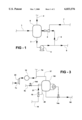
- FIG. 1 is a schematic diagram of the basic reaction stage
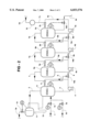
- FIG. 2 is a schematic diagram of a plurality of basic reaction stages coupled together in series.
- FIG. 3 is a schematic diagram of a regeneration stage which may form part of the apparatus.
- FIG. 1 discloses the basic reaction stage. Liquid spent caustic from a source thereof, enters the residence time section of the reactor 8 through inlet line 1. It is taken out of the reactor through liquid line 3 where it has kinetic and pressure energy imparted to it by circulating pump 4. The high energy liquid is pumped to jet compressor 5 through line 6 where the energy inputted by the pump is dissipated through a nozzle and converted into mixing energy and compression energy within the jet compressor. Flue gas to the jet compressor is induced from a source through gas line 7 into the jet compressor and intimately mixed and compressed with the circulating liquid spent caustic. The compression undergone by the gas is up to a 2:1 pressure ratio. In the jet compressor the following takes place.
- the gas pressure is increased by a ratio of approximately 2:1 thereby increasing the CO 2 partial pressure and improving the mass transfer of the CO 2 from the flue gas to the liquid phase.
- gas leaner in CO 2 exits the reactor through line 2 and the decontaminated liquid is separated from the gas.
- This gas also carries with it H 2 S and any other organic or inorganic gases or vapours transferred to it in the gas/liquid exchange that has taken place in the reactor.
- the reaction stage comprises the combination of the vessel (or drum), the pumps and the jet compressor and interconnecting piping. Liquid flows into the reaction stage are balanced by liquid outflows from the reaction stage through line 9.
- FIG. 2 shows how a number of these basic reactor stages may be connected into a number of stages to achieve the completion of the three phases of reaction described in the discussion. In this illustration four reactor stages are employed.
- Spent caustic typically containing 20,000 ppm sodium sulfide, 10% caustic and 2% sodium carbonate is fed to the first reactor through feed line 1 at a controlled rate through flow control valve 14.
- Fresh water is added to the spent caustic through line 16 at a controlled rate through the flow control valve 15.
- the relative rates of spent caustic and water are determined so as to ensure that the concentration of the various salts through the different reaction stages is kept below the saturation level to ensure precipitation does not occur.
- the neutralisation phase occurs principally in the first reaction stage comprising 8, 4 and 5 together with interconnecting piping.
- CO 2 depleted gas together with H 2 S and hydrocarbon and other sulfur containing vapours leave the first stage through flame arrestor 11 under pressure control; controlled by pressure controller 13 through line 2a for incineration or other convenient disposal method.
- the largely bicarbonated liquid from Stage 2 has its bicarbonation completed in this stage and has almost all of its sulfur, hydrocarbons and sulfur compounds stripped out of it in this third stage. pH leaving this stage is between pH 6 and 8 dependant on CO 2 partial pressure and salt concentration. The H 2 S, hydrocarbon and sulfur compound rich gas is routed to Stage 2 for further reaction.
- bicarbonated liquid is reacted with flue gas rich in CO 2 .
- the hot flue gas is routed from a furnace/boiler stack or other CO 2 source through duct 7a cooled in cooling exchanger 10 and routed to the reactor through 7c.
- the last traces of H 2 S, hydrocarbons and sulfur compounds are stripped from the bicarbonated spent caustic. Gas containing these traces of H 2 S, hydrocarbon and sulfur compounds are taken overhead to stage 3 for further reaction.
- the sodium bicarbonate solution, sulfur and contaminant free, is sent to sewer through level control valve 14 and line through 9c.
- Typical pressures through the process are at 7d 100 kPa, at stage 4 200 kPa, at stage 3 250 kPa, at stage 2 300 kPa and at stage 1 300 kPa.
- Pressure however is one of the design variables to be optimised on number of stages and can be boosted by conventional compression ahead of stage 4 to as high as 1000 kPa to reduce equipment size in large systems.
- the higher CO 2 partial pressure provided by the higher operating pressure reduces the stable pH in the second reation phase of the process to as low as pH 6. This pushes reaction 6 and 7 markedly to the right resulting in more rapid removal of H 2 S from the liquid phase.
- FIG. 3 shows a regeneration stage which may be added after the polishing stage, stage 4, to improve the efficiency of use of the carbon dioxide.
- bicarbonate product is fed to the reactor vessel 8d through line 9c and control valve 14d.
- the reactor vessel liquid is heated by circulating it from line 20 via a steam jet ejector 18 which uses low pressure steam from line 19 to both heat the bicarbonate solution and provide the motive energy to pump the solution from the bottom of the reactor vessel and the vapour space through line 21.
- Supplementary heating with direct steam injection or other conventional heating means may also be employed.
- the bicarbonate decomposes liberating carbon dioxide, CO 2 , per the following equations. ##EQU7##
- the CO 2 evolved is wet as any water vapour carries over the overhead line 17 which routes it to the flue gas line 7d to the flue gas cooler 10.
- the addition of CO 2 to stream 7d increases the CO 2 partial pressure in the flue gas, markedly improving reaction rate and reducing the amount of flue gas required by the process.
- the inclusion of a conventional compressor (22) downstream of gas cooler (10) can further enhance the efficient utilisation of CO 2 and reduce the amount of flue gas required by the process.
- Sodium carbonate with a pH of about pH 10 is routed to sewer through control valve 14e and line 9d usually through a cooler for eventual disposal to the environment.
- the flow rate through the process is limited by CO 2 partial pressure, temperature, concentration of sulfide, strength of the spent caustic and any contaminants which may limit or accelerate reaction rate.
- This process is essentially a continuous process.
- another unique property of this invention is that it can be readily varied from continuous to fully batch. This flexibility can be achieved by loading up with spent caustic, stop feed and start the pumps and flue gas and run it until all sulfide, organic sulfur compounds and hydrocarbons have been removed and then dump to sewer and start again or it can be run on a continuous basis varying the rate of feed to suit the circumstances.
Landscapes
- Chemical & Material Sciences (AREA)
- Organic Chemistry (AREA)
- Chemical Kinetics & Catalysis (AREA)
- Dispersion Chemistry (AREA)
- Treating Waste Gases (AREA)
- Chemical Treatment Of Metals (AREA)
- Processing Of Solid Wastes (AREA)
- Treatment Of Sludge (AREA)
Applications Claiming Priority (3)
| Application Number | Priority Date | Filing Date | Title |
|---|---|---|---|
| AUPM267293 | 1993-11-26 | ||
| AUPM2672 | 1993-11-26 | ||
| PCT/AU1994/000729 WO1995014526A1 (fr) | 1993-11-26 | 1994-11-25 | Traitement chimique des dechets |
Publications (1)
| Publication Number | Publication Date |
|---|---|
| US6033576A true US6033576A (en) | 2000-03-07 |
Family
ID=3777383
Family Applications (1)
| Application Number | Title | Priority Date | Filing Date |
|---|---|---|---|
| US08/649,598 Expired - Fee Related US6033576A (en) | 1993-11-26 | 1994-11-25 | Chemical waste treatment |
Country Status (8)
| Country | Link |
|---|---|
| US (1) | US6033576A (fr) |
| EP (1) | EP0730491A4 (fr) |
| JP (1) | JPH09509358A (fr) |
| CN (1) | CN1142200A (fr) |
| AU (1) | AU1059795A (fr) |
| BR (1) | BR9408156A (fr) |
| CA (1) | CA2177151A1 (fr) |
| WO (1) | WO1995014526A1 (fr) |
Cited By (11)
| Publication number | Priority date | Publication date | Assignee | Title |
|---|---|---|---|---|
| US6322055B1 (en) | 2000-10-02 | 2001-11-27 | Eco-Oxygen Technologies, Llc | Gas dissolving apparatus and method |
| US20030147797A1 (en) * | 2001-02-26 | 2003-08-07 | Basok Boris Iv. | Pulse energy transformation |
| US6668556B2 (en) | 2002-04-18 | 2003-12-30 | Eco Oxygen Technologies, Llc. | Gas transfer energy recovery and effervescence prevention apparatus and method |
| US20040040671A1 (en) * | 2002-09-04 | 2004-03-04 | Duesel Bernard F. | Treatment of spent caustic refinery effluents |
| US20040245188A1 (en) * | 2003-06-06 | 2004-12-09 | Chowdhury Ajit K. | Caustic solution treatment process |
| US20050173326A1 (en) * | 2004-02-09 | 2005-08-11 | Eco Oxygen Technologies, Llc | Superoxygenation of raw wastewater for odor/corrosion control |
| US20060231500A1 (en) * | 2004-02-09 | 2006-10-19 | Eco Oxygen Technologies, Llc | Method and apparatus for control of a gas or chemical |
| US20110272365A1 (en) * | 2010-05-07 | 2011-11-10 | Encana Corporation | Removal of hydrogen sulfide from water |
| US9447327B2 (en) | 2010-11-29 | 2016-09-20 | Exxonmobil Research And Engineering Company | Asphalt oxidation process using liquid jet ejection |
| US20210129041A1 (en) * | 2019-10-31 | 2021-05-06 | Canon Kabushiki Kaisha | Ultrafine bubble generating apparatus and controlling method thereof |
| US20220047989A1 (en) * | 2019-12-10 | 2022-02-17 | Kenji SORIMACHI | Carbon dioxide fixation apparatus |
Families Citing this family (2)
| Publication number | Priority date | Publication date | Assignee | Title |
|---|---|---|---|---|
| AUPO535897A0 (en) * | 1997-02-28 | 1997-03-20 | Hyperno Pty Ltd | Multiphase physico-chemical reactor |
| DE10010287B4 (de) * | 2000-02-25 | 2004-02-12 | Infineon Technologies Ag | Verfahren zur Herstellung von flüssigen Gemischen für das chemisch-mechanische Polieren von Wafern |
Citations (21)
| Publication number | Priority date | Publication date | Assignee | Title |
|---|---|---|---|---|
| DE2331462A1 (de) * | 1973-06-20 | 1975-01-16 | Rexroth Gmbh G L | Hydropumpe |
| US3884803A (en) * | 1972-06-23 | 1975-05-20 | Union Oil Co | Process for separating low api gravity oil from water |
| US4026817A (en) * | 1974-07-04 | 1977-05-31 | Snam Progetti S.P.A. | Method for the preparation in a continuous way of water/oil emulsions and apparatus suitable therefor |
| FR2385438A1 (fr) * | 1977-03-31 | 1978-10-27 | Alsthom Atlantique | Procede et dispositif d'injection d'un composant dans un ecoulement |
| US4137163A (en) * | 1977-07-18 | 1979-01-30 | Eberle Tanning Company | Treatment of vegetable tanning wastes |
| US4162970A (en) * | 1976-07-31 | 1979-07-31 | Bayer Aktiengesellschaft | Injectors and their use in gassing liquids |
| US4252654A (en) * | 1978-06-21 | 1981-02-24 | Messer Griesheim Gmbh | Process for water treatment |
| FR2484862A1 (fr) * | 1980-06-18 | 1981-12-24 | Inst Nat Rech Chimique | Procede et dispositif pour le transfert de gaz dans un liquide applicable en particulier au traitement des eaux, en biotechnologie et dans l'industrie chimique |
| GB2089234A (en) * | 1980-12-17 | 1982-06-23 | Ici Plc | Gas-liquid contacting |
| AU9181982A (en) * | 1981-12-22 | 1983-06-30 | Kozponti Valto-Es Hitelbank Rt | Contacting liquids with gases |
| AU1080983A (en) * | 1982-01-29 | 1983-08-04 | Shell Internationale Research Maatschappij B.V. | Process for contacting a gas with an atomized liquid |
| US4416610A (en) * | 1980-03-14 | 1983-11-22 | Hydroil, Inc. | Water-in-oil emulsifier and oil-burner boiler system incorporating such emulsifier |
| AU1297288A (en) * | 1987-02-02 | 1988-08-24 | Fuel Tech. Inc. | Process & apparatus for reducing the concentration of pollutants in an effluent |
| US4874521A (en) * | 1988-10-18 | 1989-10-17 | Boise Cascade Corporation | Pulp mill effluent color removal process |
| US5087377A (en) * | 1987-08-03 | 1992-02-11 | Microlift Systems Limited Partnership | High pressure oxygen-saturated water-treatment |
| AU3034392A (en) * | 1992-01-21 | 1993-07-22 | Boc Group Plc, The | Treatment of liquids |
| WO1994000224A1 (fr) * | 1992-06-25 | 1994-01-06 | Envirocare Systems, Inc. | Epurateur a venturi ameliore et procede d'epuration |
| WO1994002234A1 (fr) * | 1992-07-16 | 1994-02-03 | Noranda Inc. | Injecteur de gaz rotatif |
| US5314613A (en) * | 1989-09-25 | 1994-05-24 | Gaetano Russo | Process and apparatus for oil decontamination |
| US5350511A (en) * | 1990-01-29 | 1994-09-27 | Yasuyuki Sakurada | Sewage purification apparatus |
| US5403475A (en) * | 1993-01-22 | 1995-04-04 | Allen; Judith L. | Liquid decontamination method |
Family Cites Families (7)
| Publication number | Priority date | Publication date | Assignee | Title |
|---|---|---|---|---|
| FR1145197A (fr) * | 1955-11-14 | 1957-10-23 | Procédé et dispositif industriels pour l'obtention de hauts rendements, dans les réactions de contact, en phases gazeuse, liquide et éventuellement solide, applicables à tous processus chimiques, comme, par exemple, l'hydrogénation | |
| US3655343A (en) * | 1970-04-13 | 1972-04-11 | Owens Illinois Inc | Apparatus for oxidizing a spent pulping liquor |
| FR2187398A1 (en) * | 1972-06-06 | 1974-01-18 | Degremont | Waste water treatment chemical reactor - using kinetic energy of input solution to produce rapid homogeneous blend with flocculating reagents etc |
| DE2607963A1 (de) * | 1976-02-27 | 1977-09-01 | Metallgesellschaft Ag | Verfahren und vorrichtung zum begasen von fluessigkeiten |
| US4164541A (en) * | 1976-11-22 | 1979-08-14 | Lubas William | Venturi mixer |
| DD132990A1 (de) * | 1977-08-12 | 1978-11-22 | Egon Schlosser | Drehhubkolben-brennkraftmotor |
| DE3302797A1 (de) * | 1983-01-28 | 1984-08-02 | Seitz Enzinger Noll Maschinenbau Ag, 6800 Mannheim | Rohrreaktor |
-
1994
- 1994-11-25 US US08/649,598 patent/US6033576A/en not_active Expired - Fee Related
- 1994-11-25 WO PCT/AU1994/000729 patent/WO1995014526A1/fr not_active Application Discontinuation
- 1994-11-25 EP EP95901285A patent/EP0730491A4/fr not_active Withdrawn
- 1994-11-25 AU AU10597/95A patent/AU1059795A/en not_active Abandoned
- 1994-11-25 BR BR9408156A patent/BR9408156A/pt not_active Application Discontinuation
- 1994-11-25 CA CA002177151A patent/CA2177151A1/fr not_active Abandoned
- 1994-11-25 JP JP7514701A patent/JPH09509358A/ja active Pending
- 1994-11-25 CN CN94194874A patent/CN1142200A/zh active Pending
Patent Citations (21)
| Publication number | Priority date | Publication date | Assignee | Title |
|---|---|---|---|---|
| US3884803A (en) * | 1972-06-23 | 1975-05-20 | Union Oil Co | Process for separating low api gravity oil from water |
| DE2331462A1 (de) * | 1973-06-20 | 1975-01-16 | Rexroth Gmbh G L | Hydropumpe |
| US4026817A (en) * | 1974-07-04 | 1977-05-31 | Snam Progetti S.P.A. | Method for the preparation in a continuous way of water/oil emulsions and apparatus suitable therefor |
| US4162970A (en) * | 1976-07-31 | 1979-07-31 | Bayer Aktiengesellschaft | Injectors and their use in gassing liquids |
| FR2385438A1 (fr) * | 1977-03-31 | 1978-10-27 | Alsthom Atlantique | Procede et dispositif d'injection d'un composant dans un ecoulement |
| US4137163A (en) * | 1977-07-18 | 1979-01-30 | Eberle Tanning Company | Treatment of vegetable tanning wastes |
| US4252654A (en) * | 1978-06-21 | 1981-02-24 | Messer Griesheim Gmbh | Process for water treatment |
| US4416610A (en) * | 1980-03-14 | 1983-11-22 | Hydroil, Inc. | Water-in-oil emulsifier and oil-burner boiler system incorporating such emulsifier |
| FR2484862A1 (fr) * | 1980-06-18 | 1981-12-24 | Inst Nat Rech Chimique | Procede et dispositif pour le transfert de gaz dans un liquide applicable en particulier au traitement des eaux, en biotechnologie et dans l'industrie chimique |
| GB2089234A (en) * | 1980-12-17 | 1982-06-23 | Ici Plc | Gas-liquid contacting |
| AU9181982A (en) * | 1981-12-22 | 1983-06-30 | Kozponti Valto-Es Hitelbank Rt | Contacting liquids with gases |
| AU1080983A (en) * | 1982-01-29 | 1983-08-04 | Shell Internationale Research Maatschappij B.V. | Process for contacting a gas with an atomized liquid |
| AU1297288A (en) * | 1987-02-02 | 1988-08-24 | Fuel Tech. Inc. | Process & apparatus for reducing the concentration of pollutants in an effluent |
| US5087377A (en) * | 1987-08-03 | 1992-02-11 | Microlift Systems Limited Partnership | High pressure oxygen-saturated water-treatment |
| US4874521A (en) * | 1988-10-18 | 1989-10-17 | Boise Cascade Corporation | Pulp mill effluent color removal process |
| US5314613A (en) * | 1989-09-25 | 1994-05-24 | Gaetano Russo | Process and apparatus for oil decontamination |
| US5350511A (en) * | 1990-01-29 | 1994-09-27 | Yasuyuki Sakurada | Sewage purification apparatus |
| AU3034392A (en) * | 1992-01-21 | 1993-07-22 | Boc Group Plc, The | Treatment of liquids |
| WO1994000224A1 (fr) * | 1992-06-25 | 1994-01-06 | Envirocare Systems, Inc. | Epurateur a venturi ameliore et procede d'epuration |
| WO1994002234A1 (fr) * | 1992-07-16 | 1994-02-03 | Noranda Inc. | Injecteur de gaz rotatif |
| US5403475A (en) * | 1993-01-22 | 1995-04-04 | Allen; Judith L. | Liquid decontamination method |
Cited By (17)
| Publication number | Priority date | Publication date | Assignee | Title |
|---|---|---|---|---|
| US6322055B1 (en) | 2000-10-02 | 2001-11-27 | Eco-Oxygen Technologies, Llc | Gas dissolving apparatus and method |
| US6474627B2 (en) | 2000-10-02 | 2002-11-05 | Eco-Oxygen Technologies, Llc | Gas dissolving apparatus and method |
| US6485003B2 (en) | 2000-10-02 | 2002-11-26 | Richard E. Speece | Gas dissolving apparatus and method |
| US20030147797A1 (en) * | 2001-02-26 | 2003-08-07 | Basok Boris Iv. | Pulse energy transformation |
| US6668556B2 (en) | 2002-04-18 | 2003-12-30 | Eco Oxygen Technologies, Llc. | Gas transfer energy recovery and effervescence prevention apparatus and method |
| US20040040671A1 (en) * | 2002-09-04 | 2004-03-04 | Duesel Bernard F. | Treatment of spent caustic refinery effluents |
| US20070251650A1 (en) * | 2002-09-04 | 2007-11-01 | Duesel Bernard F Jr | Treatment of spent caustic refinery effluents |
| US7005076B2 (en) * | 2003-06-06 | 2006-02-28 | Rmt, Inc. | Caustic solution treatment process |
| US20040245188A1 (en) * | 2003-06-06 | 2004-12-09 | Chowdhury Ajit K. | Caustic solution treatment process |
| US20050173326A1 (en) * | 2004-02-09 | 2005-08-11 | Eco Oxygen Technologies, Llc | Superoxygenation of raw wastewater for odor/corrosion control |
| US20060231500A1 (en) * | 2004-02-09 | 2006-10-19 | Eco Oxygen Technologies, Llc | Method and apparatus for control of a gas or chemical |
| US20110024362A1 (en) * | 2004-02-09 | 2011-02-03 | Eco Oxygen Technologies, Llc | Method and apparatus for control of a gas or chemical |
| US8580125B2 (en) | 2004-02-09 | 2013-11-12 | Eco Oxygen Technologies, Llc | Method and apparatus for control of a gas or chemical |
| US20110272365A1 (en) * | 2010-05-07 | 2011-11-10 | Encana Corporation | Removal of hydrogen sulfide from water |
| US9447327B2 (en) | 2010-11-29 | 2016-09-20 | Exxonmobil Research And Engineering Company | Asphalt oxidation process using liquid jet ejection |
| US20210129041A1 (en) * | 2019-10-31 | 2021-05-06 | Canon Kabushiki Kaisha | Ultrafine bubble generating apparatus and controlling method thereof |
| US20220047989A1 (en) * | 2019-12-10 | 2022-02-17 | Kenji SORIMACHI | Carbon dioxide fixation apparatus |
Also Published As
| Publication number | Publication date |
|---|---|
| AU1059795A (en) | 1995-06-13 |
| WO1995014526A1 (fr) | 1995-06-01 |
| CA2177151A1 (fr) | 1995-06-01 |
| EP0730491A1 (fr) | 1996-09-11 |
| CN1142200A (zh) | 1997-02-05 |
| BR9408156A (pt) | 1997-08-05 |
| JPH09509358A (ja) | 1997-09-22 |
| EP0730491A4 (fr) | 1997-12-17 |
Similar Documents
| Publication | Publication Date | Title |
|---|---|---|
| US6033576A (en) | Chemical waste treatment | |
| CA2497677C (fr) | Traitement d'effluents caustiques uses de raffinage | |
| US5690899A (en) | Process for removing sulphur dioxide from flue gas | |
| CA1311343C (fr) | Methode d'elimination des matieres polluantes d'un gaz d'echappement | |
| CA2321300C (fr) | Pretraitement de caustique epuise et processus d'oxydation poussee | |
| CN108722148B (zh) | 含二氧化碳和硫化氢气体的处理方法及装置 | |
| CA2229924A1 (fr) | Procede de traitement destine a reduire la durete de l'eau d'un gisement petrolifere | |
| WO1980001377A1 (fr) | Amelioration de l'elimination du so2 | |
| RU2103050C1 (ru) | Способ селективного удаления сульфида водорода из газа и устройство для его осуществления | |
| KR101070528B1 (ko) | 폐가성소다의 처리 방법 | |
| CN1111582C (zh) | 石油炼制工业油品精制废碱液的处理方法 | |
| EP0127206A1 (fr) | Procédé pour désulfurer des gaz combustibles | |
| KR20010088313A (ko) | 사용된 부식성 스트림의 처리 방법 | |
| US5378441A (en) | Method to scavenge hydrogen sulfide from natural gas | |
| KR100478271B1 (ko) | 습식산화방법 | |
| CN108722149B (zh) | 一种酸性气的处理方法及装置 | |
| RU2120464C1 (ru) | Способ дезодорирующей очистки нефти и газоконденсата от сероводорода и низкомолекулярных меркаптанов и установка для его осуществления | |
| CN113213673B (zh) | 一种庚烯酮焦油废水的处理方法 | |
| CN108722135B (zh) | 一种酸性气组合处理工艺及系统 | |
| CA2312316C (fr) | Methode et appareil d'elimination de sulfure d'hydrogene | |
| CN108722140B (zh) | 一种酸性气处理工艺及系统 | |
| CN108722139B (zh) | 一种处理酸性气的方法及装置 | |
| JPS6053806B2 (ja) | 硫酸スラツジの処理方法 | |
| EP3668819A1 (fr) | Élimination de sulfate de caustique usé oxydé par voie humide | |
| JPS5854628B2 (ja) | 硫化水素含有廃液の処理法 |
Legal Events
| Date | Code | Title | Description |
|---|---|---|---|
| AS | Assignment |
Owner name: HYPERNO PROPRIETARY LIMITED, AUSTRALIA Free format text: ASSIGNMENT OF ASSIGNORS INTEREST;ASSIGNOR:RUSSO, GAETANO;REEL/FRAME:008188/0275 Effective date: 19960628 |
|
| REMI | Maintenance fee reminder mailed | ||
| FPAY | Fee payment |
Year of fee payment: 4 |
|
| SULP | Surcharge for late payment | ||
| REMI | Maintenance fee reminder mailed | ||
| LAPS | Lapse for failure to pay maintenance fees | ||
| STCH | Information on status: patent discontinuation |
Free format text: PATENT EXPIRED DUE TO NONPAYMENT OF MAINTENANCE FEES UNDER 37 CFR 1.362 |
|
| FP | Expired due to failure to pay maintenance fee |
Effective date: 20080307 |