US5961160A - High-pressure connection system - Google Patents
High-pressure connection system Download PDFInfo
- Publication number
- US5961160A US5961160A US09/011,221 US1122198A US5961160A US 5961160 A US5961160 A US 5961160A US 1122198 A US1122198 A US 1122198A US 5961160 A US5961160 A US 5961160A
- Authority
- US
- United States
- Prior art keywords
- sealing ring
- sealing
- retention body
- ring
- pipe
- Prior art date
- Legal status (The legal status is an assumption and is not a legal conclusion. Google has not performed a legal analysis and makes no representation as to the accuracy of the status listed.)
- Expired - Fee Related
Links
- 238000007789 sealing Methods 0.000 claims abstract description 223
- 230000014759 maintenance of location Effects 0.000 claims abstract description 77
- 230000008878 coupling Effects 0.000 claims abstract description 32
- 238000010168 coupling process Methods 0.000 claims abstract description 32
- 238000005859 coupling reaction Methods 0.000 claims abstract description 32
- 229920001971 elastomer Polymers 0.000 claims description 61
- 239000000806 elastomer Substances 0.000 claims description 61
- 230000002093 peripheral effect Effects 0.000 claims description 37
- 239000000463 material Substances 0.000 claims description 13
- 230000013011 mating Effects 0.000 claims 2
- 241000283690 Bos taurus Species 0.000 claims 1
- 238000005520 cutting process Methods 0.000 description 53
- 230000008901 benefit Effects 0.000 description 13
- 230000000694 effects Effects 0.000 description 8
- 210000002445 nipple Anatomy 0.000 description 8
- 230000006872 improvement Effects 0.000 description 7
- 239000012530 fluid Substances 0.000 description 6
- 239000003566 sealing material Substances 0.000 description 6
- 239000002131 composite material Substances 0.000 description 4
- 238000007493 shaping process Methods 0.000 description 4
- 230000004323 axial length Effects 0.000 description 3
- 238000009434 installation Methods 0.000 description 3
- 238000004519 manufacturing process Methods 0.000 description 3
- 238000010008 shearing Methods 0.000 description 3
- 238000003466 welding Methods 0.000 description 3
- 230000002028 premature Effects 0.000 description 2
- 230000009467 reduction Effects 0.000 description 2
- 230000008439 repair process Effects 0.000 description 2
- 239000011324 bead Substances 0.000 description 1
- 238000005452 bending Methods 0.000 description 1
- 230000008859 change Effects 0.000 description 1
- 239000003795 chemical substances by application Substances 0.000 description 1
- 230000006835 compression Effects 0.000 description 1
- 238000007906 compression Methods 0.000 description 1
- 230000007423 decrease Effects 0.000 description 1
- 238000006073 displacement reaction Methods 0.000 description 1
- 238000009826 distribution Methods 0.000 description 1
- 238000005516 engineering process Methods 0.000 description 1
- 239000007789 gas Substances 0.000 description 1
- 239000001307 helium Substances 0.000 description 1
- 229910052734 helium Inorganic materials 0.000 description 1
- SWQJXJOGLNCZEY-UHFFFAOYSA-N helium atom Chemical compound [He] SWQJXJOGLNCZEY-UHFFFAOYSA-N 0.000 description 1
- 238000003780 insertion Methods 0.000 description 1
- 230000037431 insertion Effects 0.000 description 1
- 238000000034 method Methods 0.000 description 1
- 239000000203 mixture Substances 0.000 description 1
- 230000035515 penetration Effects 0.000 description 1
- 238000002360 preparation method Methods 0.000 description 1
- 238000003825 pressing Methods 0.000 description 1
- 230000004044 response Effects 0.000 description 1
- 238000000926 separation method Methods 0.000 description 1
- 230000035939 shock Effects 0.000 description 1
Images

Classifications
-
- F—MECHANICAL ENGINEERING; LIGHTING; HEATING; WEAPONS; BLASTING
- F16—ENGINEERING ELEMENTS AND UNITS; GENERAL MEASURES FOR PRODUCING AND MAINTAINING EFFECTIVE FUNCTIONING OF MACHINES OR INSTALLATIONS; THERMAL INSULATION IN GENERAL
- F16L—PIPES; JOINTS OR FITTINGS FOR PIPES; SUPPORTS FOR PIPES, CABLES OR PROTECTIVE TUBING; MEANS FOR THERMAL INSULATION IN GENERAL
- F16L19/00—Joints in which sealing surfaces are pressed together by means of a member, e.g. a swivel nut, screwed on, or into, one of the joint parts
- F16L19/08—Joints in which sealing surfaces are pressed together by means of a member, e.g. a swivel nut, screwed on, or into, one of the joint parts with metal rings which bite into the wall of the pipe
- F16L19/10—Joints in which sealing surfaces are pressed together by means of a member, e.g. a swivel nut, screwed on, or into, one of the joint parts with metal rings which bite into the wall of the pipe the profile of the ring being altered
-
- F—MECHANICAL ENGINEERING; LIGHTING; HEATING; WEAPONS; BLASTING
- F16—ENGINEERING ELEMENTS AND UNITS; GENERAL MEASURES FOR PRODUCING AND MAINTAINING EFFECTIVE FUNCTIONING OF MACHINES OR INSTALLATIONS; THERMAL INSULATION IN GENERAL
- F16L—PIPES; JOINTS OR FITTINGS FOR PIPES; SUPPORTS FOR PIPES, CABLES OR PROTECTIVE TUBING; MEANS FOR THERMAL INSULATION IN GENERAL
- F16L19/00—Joints in which sealing surfaces are pressed together by means of a member, e.g. a swivel nut, screwed on, or into, one of the joint parts
- F16L19/02—Pipe ends provided with collars or flanges, integral with the pipe or not, pressed together by a screwed member
- F16L19/0212—Pipe ends provided with collars or flanges, integral with the pipe or not, pressed together by a screwed member using specially adapted sealing means
- F16L19/0218—Pipe ends provided with collars or flanges, integral with the pipe or not, pressed together by a screwed member using specially adapted sealing means comprising only sealing rings
-
- F—MECHANICAL ENGINEERING; LIGHTING; HEATING; WEAPONS; BLASTING
- F16—ENGINEERING ELEMENTS AND UNITS; GENERAL MEASURES FOR PRODUCING AND MAINTAINING EFFECTIVE FUNCTIONING OF MACHINES OR INSTALLATIONS; THERMAL INSULATION IN GENERAL
- F16L—PIPES; JOINTS OR FITTINGS FOR PIPES; SUPPORTS FOR PIPES, CABLES OR PROTECTIVE TUBING; MEANS FOR THERMAL INSULATION IN GENERAL
- F16L19/00—Joints in which sealing surfaces are pressed together by means of a member, e.g. a swivel nut, screwed on, or into, one of the joint parts
- F16L19/08—Joints in which sealing surfaces are pressed together by means of a member, e.g. a swivel nut, screwed on, or into, one of the joint parts with metal rings which bite into the wall of the pipe
- F16L19/083—Joints in which sealing surfaces are pressed together by means of a member, e.g. a swivel nut, screwed on, or into, one of the joint parts with metal rings which bite into the wall of the pipe the longitudinal cross-section of the ring not being modified during clamping
- F16L19/086—Joints in which sealing surfaces are pressed together by means of a member, e.g. a swivel nut, screwed on, or into, one of the joint parts with metal rings which bite into the wall of the pipe the longitudinal cross-section of the ring not being modified during clamping with additional sealing means
-
- Y—GENERAL TAGGING OF NEW TECHNOLOGICAL DEVELOPMENTS; GENERAL TAGGING OF CROSS-SECTIONAL TECHNOLOGIES SPANNING OVER SEVERAL SECTIONS OF THE IPC; TECHNICAL SUBJECTS COVERED BY FORMER USPC CROSS-REFERENCE ART COLLECTIONS [XRACs] AND DIGESTS
- Y10—TECHNICAL SUBJECTS COVERED BY FORMER USPC
- Y10S—TECHNICAL SUBJECTS COVERED BY FORMER USPC CROSS-REFERENCE ART COLLECTIONS [XRACs] AND DIGESTS
- Y10S285/00—Pipe joints or couplings
- Y10S285/906—Equivalents
-
- Y—GENERAL TAGGING OF NEW TECHNOLOGICAL DEVELOPMENTS; GENERAL TAGGING OF CROSS-SECTIONAL TECHNOLOGIES SPANNING OVER SEVERAL SECTIONS OF THE IPC; TECHNICAL SUBJECTS COVERED BY FORMER USPC CROSS-REFERENCE ART COLLECTIONS [XRACs] AND DIGESTS
- Y10—TECHNICAL SUBJECTS COVERED BY FORMER USPC
- Y10S—TECHNICAL SUBJECTS COVERED BY FORMER USPC CROSS-REFERENCE ART COLLECTIONS [XRACs] AND DIGESTS
- Y10S285/00—Pipe joints or couplings
- Y10S285/915—Mastic
Definitions
- the invention concerns a connection system for high-pressure screwed pipe joints having a standardized retention body with a 24°-connection, a likewise standardized coupling ring for producing a high-pressure connection, a pipe or a connecting member for connecting other system components and a sealing ring which is sealed by means of an elastomer high-pressure seal relative to the retention body and relative to the pipe and which has a front surface which is immediately adjacent to a front surface of the retention body.
- connection system of this kind is known in the art from DE 40 38 539 C1.
- connection system having two-part rings in combination with a DIN retention body with a DIN coupling ring as, e. g. described in the above cited DE 40 38 539 C1.
- This conventional system advantageously separates the holding function and the sealing function.
- a two-part ring due to the separated clamping and resilient functions, has substantial advantages compared to a one-part ring having a double function.
- the system in accordance with DE 27 12 614 A1 is distinguished from the connection system according to the above cited DE 40 38 539 C1 only in that the first system does not utilize a DIN connector and has therefore not been commercially successful.
- connection system in accordance with DE 40 38 539 C1 had essentially taken adopted the partial solution already known in the art from previous publications (for the sealing element e. g. DE 90 03 299.3 U1; for the cutting ring and the cutting ring sided portion of the sealing element e. g. DE 27 12 614 A1 or DT 15 25 666 C3) and transformed same into a DIN compatible form.
- the conventional system still has serious disadvantages:
- This type of conventional welding nipple screwed pipe joint is intended to be used, in particular, under difficult operating conditions, for example, under extreme vibration and alternating load conditions, high-pressure shocks in installations, and extreme temperature and temperature variations.
- this type of high-pressure screw pipe joint is utilized in installations with which down times would be associated with very high costs.
- a substantial disadvantage of this connecting method is, however, that the welding nipples are relatively expensive lathe components the assembly of which (welding) is also time consuming and therefore expensive and the weldment nipple leads to additional substantial inventory costs.
- the hydraulic high-pressure sealing effect is intended to be gained solely via an area seal between the tapered outer surface of the shaped tapered seal on the pipe end and the conical inner surface in the retention body. This could hardly be tolerated in particular, in installations where down times would lead to extremely high costs.
- a retroactive exchange of damaged sealing elements is essentially impossible, since, when tightening the retention body against the end of the pipe using a coupling ring the tapered seal formed on the end of the pipe would most likely be deformed so that, after loosening and renewed tightening of the pipe joint, the required high-pressure sealing which might have been present following first assembly of the pipe joint would only rarely be re-established.
- connection system having the features described above which, with as few technical changes as possible, combines the advantages of the system having a two-part ring with an improved sealing performance of less rigid systems, wherein a retroactive exchange of damaged sealing elements is facilitated and which can, in principle, be utilized not only with pipe connections having cutting rings but also with those having tapered seals.
- the elastomer high-pressure seal comprises a first elastomer sealing element disposed between the front surface of the retention body and the sealing ring as well as a second sealing element disposed between a surface of the sealing ring facing the pipe or the connecting member and the outer wall of the pipe or connecting member.
- two spatially separated sealing zones are created namely, via the first elastomer sealing element, between the sealing ring and the retention body and, via the second elastomer sealing ring, between the sealing ring and the pipe.
- the advantages of a specialized sealing ring are maintained, using an elastomer sealing element, which does not have to perform a holding function, rather only has to guarantee the sealing function.
- the sealing behavior is substantially improved through the spatial separation of the two sealing locations, the advantages of which are per se known in the art through DE 42 29 502 A1.
- the elastomer seal as seen in the direction of the fluid which is to be outwardly sealed, is positioned in front of the metallic cutting seal of the cutting ring so that the cutting seal performs a certain added safety function in the event that the elastomer seal between the sealing ring and the pipe fails.
- configuration of the second elastomer seal directly following the cutting ring causes the material displacement effected by the cutting ring on the outer side of the pipe to substantially improve the sealing properties of the second elastomer seal.
- connection system in accordance with the invention can be loosened by unscrewing the coupling ring.
- the cutting ring thereby remains substantially stationary and imbedded in the pipe.
- the sealing ring with the elastomer sealing element can then easily be replaced with another sealing ring.
- the elastomer sealing element per se can also be replaced without having to worry about the above described negative effects of the drawing-in of elastomer material into a gap.
- An additional simple retroactive possibility for repair of a leaking elastomer seal in the connecting system in accordance with the invention is effected through introduction of a conventional O-ring into the conical region of the retention body, to at least effect a sealing composite which is per se known in the art from the above cited DE 40 38 539 C1.
- the sealing ring having the elastomer sealing element in accordance with the connecting system of the invention can advantageously also be used to replace damaged conventional sealing rings in an already assembled system of prior art should leaks occur therein. Due to the requirements imposed through use of a standardized retention body and a DIN coupling ring in the connecting system in accordance with the invention, one is assured of geometric compatibility of the two-part ring so that one must only take into consideration that the sealing ring of the connecting system in accordance with the invention be adapted, at its side facing the cutting or clamping ring, thereto.
- a highly important additional advantage of the present invention is that the proposed connecting system can be used not only in connection with cutting seals but also for tapered seal pipe connections.
- the retention part is not, as had been common, pulled directly against the tapered seal using a coupling ring, rather the sealing ring in accordance with the invention with its elastomer sealing element, is disposed between the retention body and the tapered seal.
- An additional area seal is also effected between the seating surface of the sealing ring in accordance with the invention and the outer surface of the tapered seal which replaces the conventional area seal between the conical retention bore of the retention body and the outer surface of the tapered seal.
- the sealing composition in the vicinity of the sealing ring in accordance with the invention becomes damaged, the sealing ring can be easily exchanged.
- At least the first elastomer sealing element, and preferentially also the second elastomer sealing element are accepted in a recess in the sealing ring. In this manner a substantially complete capturing of the elastomer sealing material is guaranteed.
- the first and/or second elastomer sealing element can be a separate component in the form of an O-ring, a flat sealing element or the like.
- the elastomer sealing element can also be firmly attached to the sealing ring, in-particular vulcanized or glued thereto.
- the advantage of the first mentioned embodiment is that a damaged sealing element can be separately replaced without having to replace the entire sealing ring.
- the second alternative has the advantage of simpler handling of the elastomer sealing element firmly attached to the sealing ring with only one single component having to be inserted and positioned.
- the front surface of the sealing ring limits the front side of that section of the sealing ring projecting to the furthest axial extent towards the retention body so that no portion of the sealing ring can project into the conical 24°-recess of the retention body.
- These types of embodiments can, in particular, be utilized in combination with specialized non-tapered connectors which replace the conventional standardized DIN retention body and which e.g. can have a reduced insertion depth for the pipe.
- These type of specialized connectors can have substantially increased mechanical stability compared to the standardized retention bodies and are therefore particularly suitable for use in extreme load-changing stressing of the high-pressure fluid system to be connected or with pressures which far exceed the DIN limits. In this manner, completely new kinds of applications can be established for the connecting system in accordance with the invention.
- the embodiment mentioned also has advantages when utilizing a DIN retention body. Due to the continuous front surface, it is particularly easy to work during manufacture and can therefore be sold at a lower price. In addition, substantially less sealing material is -required since it is not necessary to fill-up a large cavity as in prior art: the sealing material must only be present between the oppositely lying sealing surfaces of the retention body and sealing ring.
- the first and second elastomer sealing elements are integrally connected to each other to thereby be substantially simpler and more economical to produce than two separate sealing elements.
- the elastomer material is vulcanized onto the sealing ring only one single processing step is required.
- the embodiment mentioned can be further improved by disposing the elastomer sealing material of the elastomer high-pressure seal, in an approximately L- or U-shape fashion, around the radial inner edge of the sealing ring facing the pipe or the connecting member.
- the sealing ring can have a recess radially inward at its end side facing the retention body which extends approximately conically and which opens towards the retention body and with a sealing element having an approximately triangular cross-section adjacent to the conical recess, one outer surface of which seats on the pipe or on the connecting member and the other outer surface of which at least partially seats on the front surface of the retention body.
- This embodiment has, compared to those mentioned above, the advantage of a simpler manufacturing of the conical recess on the sealing ring.
- the alternative embodiment due to its geometric shape, provides for improved holding of the sealing element on the sealing ring.
- a connection system in accordance with the invention can have a peripheral shoulder disposed radially inwardly on the sealing ring which projects into the conical opening of the retention body in the assembled state of the connecting system.
- a particularly good capturing of the first sealing element is guaranteed with also the 24°-cone of the retention body partially functioning as a cavity wall.
- an increased sealing surface is effected between the sealing element and the retention body.
- the first and second elastomer sealing element are formed by a layer of elastomer material attached along the peripheral shoulder of the sealing ring in an integrally coupled fashion and preferentially vulcanized onto the sealing ring.
- An integral layer of this kind is particularly simple and economical to produce.
- the layer of elastomer material has a small thickness of preferentially approximately 1/2 mm or less. This thickness is normally completely sufficient.
- a configuration of the connecting system in accordance with the invention is also particularly preferred with which the peripheral shoulder is substantially cylindrical and has an axial length, such that it does not abut with the 24°-cone of the retention body in the assembled state of the connecting system.
- the connecting system in accordance of the invention is more mechanically flexible, since an additional rigid frictional connection is eliminated.
- the screw thread of the retention body is thereby load-relieved and requirements on the dimensional precision of the pipe, e. g. in a curved conduit system for fluids are reduced without compromising safety.
- the peripheral shoulder is substantially conically tapered towards the retention body, preferentially with an angle of approximately 24°.
- the conical part of the sealing element then takes over the mechanical guide function.
- substantially less sealing material is thereby required on the first elastomer sealing element.
- An embodiment of the connecting system in accordance with the invention is particularly preferred with which outer thread segments made from elastomer material and adapted to the inner thread of the coupling ring are vulcanized or glued, preferentially symmetrically, onto the outer periphery of the sealing ring.
- preassembled components can be held in the coupling ring when delivered and can be easily separated from each other by means of simple rotation without the need for tools.
- a cutting or clamping ring is provided for coaxially to the sealing ring which cuts firmly into the outer wall of the pipe or connecting member after assembly of the connecting system.
- the cutting or clamping ring has a protruding peripheral shoulder which, in the assembled state of the connecting system, projects into a radially inward conical recess of the sealing ring facing the cutting ring or clamping ring and which, departing from an approximately cylindrical extension member, has a conical slant which decreases towards the sealing ring, the slant angle of which is larger the slant angle of the corresponding conical recess of the sealing ring.
- a constriction and clamping in the middle region of the cutting ring relative to the sealing ring and the pipe occurs in the over-tightened range. In this manner, a damaging shearing of the cutting ring on the pipe via tilting of the free end of the cutting ring with respect to the pipe is prevented or at least reduced so that a higher degree of pressure safety is achieved with the connecting system.
- the pipe or the connecting member has a radially outwardly directed peripheral enlargement which serves as an abutment for the coupling ring and also as a stop for the sealing element.
- the inventive concept can also be advantageously utilized in this so-called tapered seal pipe connecting system for the cutting seal systems described above.
- providing of an elastomer sealing element in the sealing ring in accordance with the invention leads to an additional sealing effect and therefore to a substantial increase in safety for the high-pressure hydraulic connection. If a seal becomes damaged, its replacement with a new sealing ring is absolutely simple in these systems.
- the peripheral enlargement increases radially in the outward direction on the sealing ring side in a first section having low steepness, preferentially approximately 24°, and in a second section up to a maximum radial extent having increased steepness, preferentially of approximately 45°.
- the sealing ring then has, on the enlargement side, corresponding conically shaped sections, preferentially with cone angles of approximately 245° and approoximately 45°. In this fashion, a radial enlargement of the bead diameter is facilitated with tapered seals to further increase the effectiveness of the area seal between the sealing ring and the peripheral enlargement.
- the peripheral enlargement is produced by forming, without cutting, one end of the pipe or a connecting member e.g. by pressing on a pipe end press or by hydraulic shaping.
- a pipe end press e.g. by pressing on a pipe end press or by hydraulic shaping.
- high-pressure hydraulic fluids are used to press the pipe wall into the contour of a corresponding opposing shaping tool.
- peripheral enlargement is part of a lathe component, preferentially a weld nipple welded onto the pipe, as has been commercially available for many years.
- a sealing ring for a connection system of the above mentioned kind is also within the framework of the present invention which is distinguished by a conical recess along at least a portion of its radially inner side and by a flat end surface extending from an axial end and perpendicular to the symmetry axis (a) of the sealing ring.
- a first elastomer sealing element is thereby disposed on the axial end of the sealing ring having the end surface and a second elastomer sealing element is disposed on the radially innermost region of its radially inner side.
- the first and second sealing elements are integrally connected to each other.
- the conically shaped recesses of the sealing ring in accordance with the invention preferentially have a cone angle between 20° and 45° and normally the standardized 24°-conical angle.
- a radially outer section of the conically shaped recess of steeper cone angle is axially adjacent to a radially inner section of the cone-shaped recess of flatter cone angle, preferentially of approximately 24°.
- This type of sealing ring is particularly suited for a tapered seal system having two-stepped slanting of the tapered seal.
- An embodiment of the sealing ring in accordance with the invention is also advantageous with which a peripheral section is provided for on the axial end radially within the front surface which projects in the axial direction beyond the end surface as has already been described above in connection with embodiments of the connection system in accordance with the invention.
- the sealing ring in accordance with the invention has outer dimensions which permit use in a connecting system with a cutting seal as well in a connecting system with a tapered seal.
- This kind of universally applicable sealing component can, in contrast to conventional ones, provide extremely high cost savings for completely differing system components.
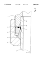
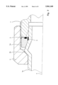
- FIG. 1 shows half of a longitudinal cut through a connecting system in accordance with the invention for high-pressure screw pipe joints having cutting seals;
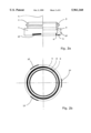
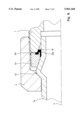
- FIG. 2a shows, in the left half, a side view of a two-part ring having a cutting ring in an embodiment of a connection system in accordance with the invention and, in the right half, a schematic longitudinal cut through same;
- FIG. 2b shows a front-sided plan view of the two-part ring in accordance with FIG. 2a;
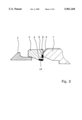
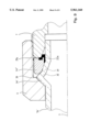
- FIG. 3 shows a schematic longitudinal cut through one half of a two-part ring having a cutting ring and a retention body in an embodiment of the connection system in accordance with the invention which has a sealing ring without a shoulder;
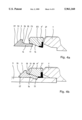
- FIG. 4a shows a longitudinal cut as in FIG. 3, but with a one-piece elastomer L-shaped sealing element
- FIG. 4b shows a longitudinal cut as in FIG. 4a, but with a cutting ring, sealing ring and retention body completely assembled in the prescribed final position without over-tightening;
- FIG. 5 shows a longitudinal cut as in FIG. 3, but with a triangular-shaped single-piece sealing element
- FIG. 6 shows a longitudinal cut as in FIG. 3, wherein the sealing ring has a peripheral shoulder projecting into the 24° cone of the retention body;
- FIG. 7 shows half of a longitudinal cut through a connecting system in accordance with the invention for high-pressure screwed pipe joints having a tapered seal, wherein the sealing ring in accordance with the invention has two separate elastomer sealing elements;
- FIG. 8 shows a longitudinal cut as in FIG. 7, however, with a one-piece sealing element on the sealing ring;
- FIG. 9 shows a longitudinal cut as in FIG. 8, however, with 24° and 45° conical surfaces having an associated pitched tapered seal.
- a pipe 7 which e. g. could also be a connecting member, is connected in a high-pressure sealing fashion to-a standardized retention body 1 having a 24° inner cone 19 via a standardized coupling ring 2, a cutting ring 3 which could be a one or two-edged cutting ring or a clamping or wedge ring for holding the pipe, and a sealing ring 4.
- the cutting ring 3 is deformed through the threaded tightening of the coupling ring 2 against the retention body 1 in such a fashion that it has cut into the outer surface of the pipe 7 to thereby effect a secure seating of the composite.
- the sealing ring 4 has a first elastomer sealing element 5 which abuts against a front surface 8 of the retention body 1 as well as a second elastomer sealing element 6 which is pushed against the outer surface of the pipe 7 which, for its part, pushes at the front side against a pipe abutment surface 18 of the retention body 1.
- the connecting system in accordance with the invention can also utilize a specialized connector (not shown in the drawing) for extremely high pressures having reduced pipe penetration depth and without a retaining cone.
- the first elastic sealing element 5 then still assumes the sealing function against the corresponding front surface of the connector.
- soft seals can also be utilized for repairs, for example O-rings or flat sealing rings made from elastomer material which then assume the sealing function of a possibly damaged first or second sealing element. This type of additional soft seal could then, as in prior art, again be captured by the 24° cone of the retention body.
- FIG. 2a shows a side view of the cutting ring 3 shown in FIG. 1 and of the sealing ring 4.
- the right side of FIG. 2a shows a schematic longitudinal cut through the two-part ring 3, 4 whereas FIG. 2b shows a plan view of the sealing ring 4 according to FIG. 2a.
- Outer threaded segments 20 made from elastomer material and adapted to the inner thread of the coupling ring 2 of FIG. 1 are distributed symmetrically about the outer periphery of the sealing ring 4, and can be vulcanized onto the sealing ring 4 or glued thereon.
- FIG. 3 shows an enlargement of the cut representation of elements of the connecting system of FIG. 1, namely the retention body 1, the sealing ring 4 and the cutting ring 3 in a pre-mounted non-tightened state.
- the sealing ring 4 thereby abuts with its end surface 9 against the end surface 8 of the retention body 1 as a result of which the first elastomer sealing element 5, captured in a recess 25 in the front surface 9 of the sealing ring 4, is pushed against the sealing end surface 8 of the retention body 1.
- the second elastomer sealing element 6 seats on the outer surface of the pipe (not shown in FIG. 3).
- FIG. 4a An embodiment of the sealing element 4' is shown in FIG. 4a with which the two elastomer sealing elements are connected to each other to form a single-piece sealing element 21 which, in the embodiment shown, is disposed approximately L-shaped about the radial inner edge 22 of the sealing ring 4'.
- FIG. 4b shows the sealing composite in the tightened state.
- the coupling ring (not shown in the figure) thereby pushes the conical surface 10 of the cutting ring 3 to displace the front section 11 of same below the inner conical surface 12 of the sealing ring 4'.
- the front section 11 is thereby deflected in an inward direction towards the pipe 7 and its lower edge is imbedded into the outer surface of pipe 7.
- the end section 11 simultaneously functions as a cavity wall for the pressure-resistent containment of the elastomer sealing element 21.
- This kind of cutting ring 3 geometry assures that, when the over-tightening region is reached during assembly, the person performing the assembly feels a clearly recognizable signal in response to the disproportionately large force increase as soon as the inner edge 18 of the sealing ring 4' abuts with the conical surface 15 of the cutting ring 3. Even if over-tightening is necessary, the present geometry of the cutting ring 3 prevents damaging shearing caused by constriction of the pipe, and an even force distribution is effected on the tensioned surface between the middle region 16 and the ring run-out 17 of the cutting ring 3 which serves for additional holding of the pipe.
- FIG. 5 An additional embodiment of the connecting system in accordance of the invention is shown in FIG. 5 where the sealing ring 4" supports a one-piece substantially triangular-shaped elastomer sealing element 23 having a bevel 24 on its radially inward outer edge.
- FIG. 6 shows an additional embodiment with which a sealing ring 4'" has a radially inward peripheral shoulder 27 which projects into the conical opening 19 of the retention body 1 in the assembled state of the connecting system.
- the axial length of the shoulder 27 is thereby chosen in such a fashion that it does not abut with the conical surface 19 of the retention body 1 even in the tightened state of the connecting system.
- the peripheral shoulder 27 creates a nearly completely closed cavity 26 for the first elastomer sealing element 5'.
- the peripheral shoulder can be substantially conical and preferentially have an angle of approximately 24° which tapers towards the retention body 1. In this manner, tightening of the connection system leads to contact with the conical surface 19 of the retention body 1, wherein the conical shoulder of the sealing ring is guided over the conical surface 19.
- FIG. 7 shows an embodiment of the connecting system in accordance with the invention having a tapered seal pipe connection.
- Forming of the end, without cutting, of a pipe 7a creates a radially outwardly directed peripheral enlargement 3a against (in the figure) the left conical side of which the 45° inner cone of the coupling ring 2 abuts whereas an adapted conical bore of a sealing ring 4a in accordance with the invention abuts on the slowly increasing 24° conical surface on the other side.
- Sealing ring 4a has a first elastomer sealing element 5 disposed on the end surface facing the retention body 1, and a second elastomer sealing element 6 seals between the radially inner side of the sealing ring 4a and the pipe.
- the peripheral edge is further removed from the end of the pipe and the 24° tapered surface does not seat in the retention body 1 rather in the corresponding conical surface of the sealing ring 4a.
- the sealing function is, in particular, assumed by the elastomer sealing elements 5, 6 and, in the cylindrical portion of the pipe end directly adjacent to its 24° conical surface. In this manner, a sealing effect is obtained which corresponds to that of the conventional cutting ring screw pipe joint so that the compressed peripheral enlargement 3a primarily assumes a holding function only.
- FIG. 8 differs essentially from that of FIG. 7 in that the sealing ring 4a' has a single-piece U-shaped sealing element 21a disposed along a peripheral shoulder 22a and projecting into the conical opening 19 of the retention body 1.
- a sealing ring 4a" is provided for which has two differing slant angles for its conically shaped section facing the enlargement, wherein one cone angle is approximately 24°, and the other approximately 45°.
- the conical tilt of the peripheral enlargement 3a' in a first section 31, is somewhat smaller, preferentially approximately 24° whereas, in a second section 32 further removed from sealing ring 4a" and up to the maximum radial extent 30 of the peripheral enlargement 3a', has a larger tilt, preferentially 45° in the radially outward direction.
- the sealing system in accordance with the invention effects improved holding of the pipe for acceptance of vibrations, bending loads, and changing loads and, particularly due to the front-sided elastomer seal on the retention body, allows for a degree of compensation of large imprecisions in the pipe axis in excess of that possible up to this point of time.
- a precise guiding of the sealing ring between the outer diameter of the pipe and the 24° conical surface of the retention body was a unconditional prerequisite for sealing the conventional system.
- the connection system in accordance with the invention a limited amount of over-tightening is possible even with thin-walled pipes with which an additional cutting-in is effected to compensate for tolerances between the outer diameter of the pipe and the inner diameter of the two-part ring.
Landscapes
- Engineering & Computer Science (AREA)
- General Engineering & Computer Science (AREA)
- Mechanical Engineering (AREA)
- Gasket Seals (AREA)
- Joints With Pressure Members (AREA)
Applications Claiming Priority (5)
| Application Number | Priority Date | Filing Date | Title |
|---|---|---|---|
| DE29513129U | 1995-08-16 | ||
| DE29513129U DE29513129U1 (de) | 1995-08-16 | 1995-08-16 | Hochdruckverbindungssystem |
| DE19541622 | 1995-11-08 | ||
| DE19541622A DE19541622A1 (de) | 1995-08-16 | 1995-11-08 | Hochdruckverbindungssystem |
| PCT/DE1996/001419 WO1997007356A1 (de) | 1995-08-16 | 1996-07-31 | Hochdruckverbindungssystem |
Publications (1)
| Publication Number | Publication Date |
|---|---|
| US5961160A true US5961160A (en) | 1999-10-05 |
Family
ID=26020193
Family Applications (1)
| Application Number | Title | Priority Date | Filing Date |
|---|---|---|---|
| US09/011,221 Expired - Fee Related US5961160A (en) | 1995-08-16 | 1996-07-31 | High-pressure connection system |
Country Status (5)
| Country | Link |
|---|---|
| US (1) | US5961160A (de) |
| EP (1) | EP0845092A1 (de) |
| CN (1) | CN1196784A (de) |
| AU (1) | AU7082396A (de) |
| WO (1) | WO1997007356A1 (de) |
Cited By (34)
| Publication number | Priority date | Publication date | Assignee | Title |
|---|---|---|---|---|
| US6168211B1 (en) * | 1997-09-29 | 2001-01-02 | Walterscheid Rohrverbindungstechnik Gmbh | Threaded connection with supporting ring |
| US6312185B1 (en) * | 1997-04-14 | 2001-11-06 | Deha Ankersysteme Gmbh & Co. Kg | Tension rod anchor having a sealing structure |
| WO2002039001A1 (de) * | 2000-11-13 | 2002-05-16 | Parker Hannifin Gmbh | Schneidringgarnitur |
| US6481763B2 (en) * | 2000-02-11 | 2002-11-19 | Superior Workshop Tool Company | Waste pipe connector |
| US6527304B1 (en) * | 2000-02-17 | 2003-03-04 | Ford Global Technologies, Inc. | Brake tube connector |
| US6755446B2 (en) | 2000-02-11 | 2004-06-29 | Superior Workshop Tool Company | Waste pipe connector |
| EP1462702A3 (de) * | 2003-03-26 | 2004-10-06 | Eifeler Maschinenbau GmbH | Rohrverbindung mit einem umgeformten Rohr |
| US20060012169A1 (en) * | 2002-09-18 | 2006-01-19 | Williams Peter C | Tube fitting with tube gripping ring and sealant |
| GB2416574A (en) * | 2004-04-28 | 2006-02-01 | Spm Flow Control Inc | Hammer union with stress reducing flange |
| US7066496B2 (en) | 2001-02-06 | 2006-06-27 | Swagelok Company | Fitting with separable gripping device for pipe and tube |
| US7108288B2 (en) | 2001-02-06 | 2006-09-19 | Swagelok Company | Tube fitting with separable tube gripping ring |
| US20080143105A1 (en) * | 2006-09-22 | 2008-06-19 | Eaton Corporation | Fluid coupling |
| US7393018B2 (en) | 2001-02-06 | 2008-07-01 | Swagelok Company | Tube fitting for stainless steel tubing |
| US7407196B2 (en) | 2003-08-06 | 2008-08-05 | Swagelok Company | Tube fitting with separable tube gripping device |
| US7416225B2 (en) | 2001-02-06 | 2008-08-26 | Swagelok Company | Fitting for metal pipe and tubing |
| WO2008154950A1 (de) * | 2007-06-18 | 2008-12-24 | Weidmann Ltd. | Verbindungsanordnung für eine rohrverschraubung |
| WO2008154951A1 (de) | 2007-06-18 | 2008-12-24 | Weidmann Ltd. | Verbindungsanordnung für eine rohrverschraubung |
| US20090102190A1 (en) * | 2007-10-19 | 2009-04-23 | O.N. Industries Co. Ltd. | Connecting Mechanism for Thin Stainless Steel Pipe and Joint |
| US20090224537A1 (en) * | 2008-03-10 | 2009-09-10 | Ford Global Technologies, Llc | Brake tube end flare |
| US20100019488A1 (en) * | 2008-07-28 | 2010-01-28 | Weimer Norris R | Hose Coupling with Flow Control |
| US7695027B2 (en) | 2004-04-22 | 2010-04-13 | Swagelok Company | Fitting for tube and pipe |
| US20100140920A1 (en) * | 2008-11-06 | 2010-06-10 | Alexander Kloss | Pipe joint including a pipe and method for producing a joint section of a pipe joint |
| US7784837B2 (en) | 2003-11-03 | 2010-08-31 | Swagelok Company | Fitting for metal pipe and tubing |
| US8038180B2 (en) | 2004-04-22 | 2011-10-18 | Swagelok Company | Fitting with taper and single ferrule |
| US20120153608A1 (en) * | 2010-12-21 | 2012-06-21 | Baker Hughes Incorporated | Wet disconnect system with post disconnection pressure integrity |
| US20130147189A1 (en) * | 2011-11-02 | 2013-06-13 | Tylok International, Inc. | Face seal conduit fitting including subassembly |
| US20150167873A1 (en) * | 2010-01-21 | 2015-06-18 | Swagelok Company | Conduit Gripping Device Having Retaining Structure for Conduit Fitting |
| US20180347731A1 (en) * | 2017-05-31 | 2018-12-06 | Hanon Systems | Metal sealing threaded (tube-o) fitting |
| US10215315B2 (en) | 2008-09-05 | 2019-02-26 | Parker-Hannifin Corporation | Tube compression fitting and flared fitting used with connection body and method of making same |
| WO2019210016A1 (en) * | 2018-04-27 | 2019-10-31 | Swagelok Company | Ferrule assembly for conduit fitting |
| US10619770B2 (en) | 2008-12-10 | 2020-04-14 | Swagelok Company | Ferrule assembly for conduit fitting |
| US11079046B2 (en) | 2014-05-09 | 2021-08-03 | Swagelok Company | Conduit fitting with components adapted for facilitating assembly |
| US20230213080A1 (en) * | 2022-01-03 | 2023-07-06 | DRiV Automotive Inc. | Damper with a slanted elliptical seal between an intermediate tube and an inner pressure tube |
| US20240117904A1 (en) * | 2020-12-23 | 2024-04-11 | Walter Stauffenberg Gmbh & Co. Kg | Sealing ring and pipe connection |
Families Citing this family (10)
| Publication number | Priority date | Publication date | Assignee | Title |
|---|---|---|---|---|
| NZ264022A (en) * | 1994-07-15 | 1998-02-26 | Hansen Dev Ltd | Pipe coupling comprising a body part, a rotatable sleeve and a circular band |
| US5882050A (en) | 1997-04-15 | 1999-03-16 | Williams; Peter C. | Ferrule with relief to reduce galling |
| TW473600B (en) | 1997-04-15 | 2002-01-21 | Swagelok Co | Tube fitting, rear ferrule for a two ferrule tube fitting and ferrule for a tube fitting and a non-flared tube fitting |
| US6629708B2 (en) | 1997-04-15 | 2003-10-07 | Swagelok Company | Ferrule with relief to reduce galling |
| ZA981411B (en) * | 1998-01-01 | 1998-09-30 | Park Sil Sang | Pipe connection |
| US7820575B2 (en) * | 2003-12-26 | 2010-10-26 | Nippon Sheet Glass Company, Limited | Near infrared absorbent green glass composition, and laminated glass using the same |
| CN100451422C (zh) * | 2005-10-24 | 2009-01-14 | 沃恩工业股份有限公司 | 密封圈以及接头和钢管的连接机构 |
| DE102012102415B4 (de) * | 2012-03-21 | 2017-09-28 | Voss Fluid Gmbh | Montagesystem für Rohrverschraubungen mit Schneidring |
| EP3433522B1 (de) | 2016-03-23 | 2023-06-21 | Swagelok Company | Leitungsendstück mit hubwiderstand |
| CN110576090B (zh) * | 2019-08-26 | 2020-11-27 | 四川航天长征装备制造有限公司 | 一种管口密封装置 |
Citations (17)
| Publication number | Priority date | Publication date | Assignee | Title |
|---|---|---|---|---|
| DE692666C (de) * | 1937-03-25 | 1940-06-24 | Eisenwerke Akt Ges Deutsche | Muffenrohrverbindung |
| US2394351A (en) * | 1942-11-10 | 1946-02-05 | Paul D Wurzburger | Vibrationproof coupling |
| US2585453A (en) * | 1949-04-08 | 1952-02-12 | John P Gallagher | Interchangeable, self-releasing, self-locking high-pressure tube and pipe connector unit |
| US2586453A (en) * | 1948-01-29 | 1952-02-19 | Hays Mfg Co | Tamperproof plug valve |
| FR1335121A (fr) * | 1962-07-05 | 1963-08-16 | Joint d'étanchéité et d'ancrage pour raccord de tuyaux | |
| US3248135A (en) * | 1963-05-27 | 1966-04-26 | Liberty Mfg Company Of Texas | Sealed slip joint coupling |
| DE1515666A1 (de) * | 1965-05-28 | 1969-10-02 | Eberle Werke Kg | Quecksilberschaltroehre mit Verdraengungskoerper fuer verzoegerte Schaltung |
| GB1233372A (de) * | 1967-08-26 | 1971-05-26 | ||
| US3676573A (en) * | 1970-06-22 | 1972-07-11 | Bunker Ramo | Coaxial connector having one-piece clamp assembly |
| US4037864A (en) * | 1975-04-14 | 1977-07-26 | Emco Ltd. | Pipe coupling |
| DE2712614A1 (de) * | 1976-04-01 | 1977-10-13 | Italo Cazzaniga | Dichtrohrfitting fuer hydraulische hochdruckkreise |
| US4136897A (en) * | 1976-04-08 | 1979-01-30 | Parker-Hannifin Corporation | Coupling device for tubular members |
| DE8017944U1 (de) * | 1979-07-06 | 1985-05-15 | Legris S.A., 35000 Rennes | Rohrleitungsverbinder |
| DE9003299U1 (de) * | 1990-03-21 | 1990-06-21 | Georg Fischer AG, Schaffhausen, CH, Niederlassung: Georg Fischer AG, 7700 Singen | Klemmverbindung für Rohre |
| DE4103266A1 (de) * | 1991-02-04 | 1992-08-13 | Ingbuero Busch Gmbh | Dichthilfe fuer rohrverschraubungen |
| DE4219722A1 (de) * | 1992-06-17 | 1993-12-23 | Klaus Lehmann | Verbindungssystem für Rohrleitungen |
| DE4229502A1 (de) * | 1992-09-04 | 1994-05-05 | Mach Montagetechnik Froehlich | Verfahren zum Montieren einer Schneidringverschraubung und Schneidring |
Family Cites Families (1)
| Publication number | Priority date | Publication date | Assignee | Title |
|---|---|---|---|---|
| DE4343005C1 (de) * | 1993-12-16 | 1995-04-06 | Gressel Ag | Rohrverschraubung in Stoßausführung |
-
1996
- 1996-07-31 WO PCT/DE1996/001419 patent/WO1997007356A1/de not_active Ceased
- 1996-07-31 US US09/011,221 patent/US5961160A/en not_active Expired - Fee Related
- 1996-07-31 AU AU70823/96A patent/AU7082396A/en not_active Abandoned
- 1996-07-31 CN CN96197004A patent/CN1196784A/zh active Pending
- 1996-07-31 EP EP96931729A patent/EP0845092A1/de not_active Ceased
Patent Citations (17)
| Publication number | Priority date | Publication date | Assignee | Title |
|---|---|---|---|---|
| DE692666C (de) * | 1937-03-25 | 1940-06-24 | Eisenwerke Akt Ges Deutsche | Muffenrohrverbindung |
| US2394351A (en) * | 1942-11-10 | 1946-02-05 | Paul D Wurzburger | Vibrationproof coupling |
| US2586453A (en) * | 1948-01-29 | 1952-02-19 | Hays Mfg Co | Tamperproof plug valve |
| US2585453A (en) * | 1949-04-08 | 1952-02-12 | John P Gallagher | Interchangeable, self-releasing, self-locking high-pressure tube and pipe connector unit |
| FR1335121A (fr) * | 1962-07-05 | 1963-08-16 | Joint d'étanchéité et d'ancrage pour raccord de tuyaux | |
| US3248135A (en) * | 1963-05-27 | 1966-04-26 | Liberty Mfg Company Of Texas | Sealed slip joint coupling |
| DE1515666A1 (de) * | 1965-05-28 | 1969-10-02 | Eberle Werke Kg | Quecksilberschaltroehre mit Verdraengungskoerper fuer verzoegerte Schaltung |
| GB1233372A (de) * | 1967-08-26 | 1971-05-26 | ||
| US3676573A (en) * | 1970-06-22 | 1972-07-11 | Bunker Ramo | Coaxial connector having one-piece clamp assembly |
| US4037864A (en) * | 1975-04-14 | 1977-07-26 | Emco Ltd. | Pipe coupling |
| DE2712614A1 (de) * | 1976-04-01 | 1977-10-13 | Italo Cazzaniga | Dichtrohrfitting fuer hydraulische hochdruckkreise |
| US4136897A (en) * | 1976-04-08 | 1979-01-30 | Parker-Hannifin Corporation | Coupling device for tubular members |
| DE8017944U1 (de) * | 1979-07-06 | 1985-05-15 | Legris S.A., 35000 Rennes | Rohrleitungsverbinder |
| DE9003299U1 (de) * | 1990-03-21 | 1990-06-21 | Georg Fischer AG, Schaffhausen, CH, Niederlassung: Georg Fischer AG, 7700 Singen | Klemmverbindung für Rohre |
| DE4103266A1 (de) * | 1991-02-04 | 1992-08-13 | Ingbuero Busch Gmbh | Dichthilfe fuer rohrverschraubungen |
| DE4219722A1 (de) * | 1992-06-17 | 1993-12-23 | Klaus Lehmann | Verbindungssystem für Rohrleitungen |
| DE4229502A1 (de) * | 1992-09-04 | 1994-05-05 | Mach Montagetechnik Froehlich | Verfahren zum Montieren einer Schneidringverschraubung und Schneidring |
Non-Patent Citations (6)
| Title |
|---|
| "Wettstreit mit alten Techniken" in the journal "fluid-technid" Verlag moderne Industrie AG, D-86895 Landsberg. pp. 12,14,15 (Jul. 1995). |
| Company prospectus "EMB" of the company Eifeler Maschinenbau H Heinen GmbH & Co., D-53901 Bad Munstereifel, p. VII/1, 2 (1995). |
| Company prospectus EMB of the company Eifeler Maschinenbau H Heinen GmbH & Co., D 53901 Bad M u nstereifel, p. VII/1, 2 (1995). * |
| O lhydraulik und Pneumatik, vol. 37, No. 4, Apr. 1, 1993, pp. 308 311 Behrens, G.: Dry Technology in der fluidischen Verbindungstechnik. * |
| Olhydraulik und Pneumatik, vol. 37, No. 4, Apr. 1, 1993, pp. 308-311 Behrens, G.: "Dry Technology" in der fluidischen Verbindungstechnik. |
| Wettstreit mit alten Techniken in the journal fluid technid Verlag moderne Industrie AG, D 86895 Landsberg. pp. 12,14,15 (Jul. 1995). * |
Cited By (55)
| Publication number | Priority date | Publication date | Assignee | Title |
|---|---|---|---|---|
| US6312185B1 (en) * | 1997-04-14 | 2001-11-06 | Deha Ankersysteme Gmbh & Co. Kg | Tension rod anchor having a sealing structure |
| US6168211B1 (en) * | 1997-09-29 | 2001-01-02 | Walterscheid Rohrverbindungstechnik Gmbh | Threaded connection with supporting ring |
| US6481763B2 (en) * | 2000-02-11 | 2002-11-19 | Superior Workshop Tool Company | Waste pipe connector |
| US6755446B2 (en) | 2000-02-11 | 2004-06-29 | Superior Workshop Tool Company | Waste pipe connector |
| US6527304B1 (en) * | 2000-02-17 | 2003-03-04 | Ford Global Technologies, Inc. | Brake tube connector |
| WO2002039001A1 (de) * | 2000-11-13 | 2002-05-16 | Parker Hannifin Gmbh | Schneidringgarnitur |
| US7740283B2 (en) | 2001-02-06 | 2010-06-22 | Swagelok Company | Tube fitting with separable tube gripping device |
| US7762592B2 (en) | 2001-02-06 | 2010-07-27 | Swagelok Company | Tube fitting for stainless steel tubing |
| US7416225B2 (en) | 2001-02-06 | 2008-08-26 | Swagelok Company | Fitting for metal pipe and tubing |
| US7066496B2 (en) | 2001-02-06 | 2006-06-27 | Swagelok Company | Fitting with separable gripping device for pipe and tube |
| US7108288B2 (en) | 2001-02-06 | 2006-09-19 | Swagelok Company | Tube fitting with separable tube gripping ring |
| US7677602B2 (en) | 2001-02-06 | 2010-03-16 | Swagelok Company | Tube fitting |
| US7815226B2 (en) | 2001-02-06 | 2010-10-19 | Swagelok Company | Fitting for metal pipe and tubing |
| US7393018B2 (en) | 2001-02-06 | 2008-07-01 | Swagelok Company | Tube fitting for stainless steel tubing |
| US20060012169A1 (en) * | 2002-09-18 | 2006-01-19 | Williams Peter C | Tube fitting with tube gripping ring and sealant |
| US7350828B2 (en) | 2002-09-18 | 2008-04-01 | Swagelok Company | Tube fitting with sealant |
| EP1462702A3 (de) * | 2003-03-26 | 2004-10-06 | Eifeler Maschinenbau GmbH | Rohrverbindung mit einem umgeformten Rohr |
| US7407196B2 (en) | 2003-08-06 | 2008-08-05 | Swagelok Company | Tube fitting with separable tube gripping device |
| US7784837B2 (en) | 2003-11-03 | 2010-08-31 | Swagelok Company | Fitting for metal pipe and tubing |
| US8038180B2 (en) | 2004-04-22 | 2011-10-18 | Swagelok Company | Fitting with taper and single ferrule |
| US7695027B2 (en) | 2004-04-22 | 2010-04-13 | Swagelok Company | Fitting for tube and pipe |
| GB2416574A (en) * | 2004-04-28 | 2006-02-01 | Spm Flow Control Inc | Hammer union with stress reducing flange |
| GB2416574B (en) * | 2004-04-28 | 2008-08-20 | Spm Flow Control Inc | Enhanced durability hammer union |
| US20080143105A1 (en) * | 2006-09-22 | 2008-06-19 | Eaton Corporation | Fluid coupling |
| WO2008154951A1 (de) | 2007-06-18 | 2008-12-24 | Weidmann Ltd. | Verbindungsanordnung für eine rohrverschraubung |
| US20100127493A1 (en) * | 2007-06-18 | 2010-05-27 | Norbert Felder | Connecting arrangement for a pipe union |
| US20100117352A1 (en) * | 2007-06-18 | 2010-05-13 | Weidmann Ltd. | Connecting arrangement for a pipe union |
| CN101711322B (zh) * | 2007-06-18 | 2012-07-04 | 韦德曼有限公司 | 用于管接头的连接装置 |
| WO2008154950A1 (de) * | 2007-06-18 | 2008-12-24 | Weidmann Ltd. | Verbindungsanordnung für eine rohrverschraubung |
| US7726701B2 (en) * | 2007-10-19 | 2010-06-01 | O.N. Industries Co., Ltd. | Connecting mechanism for thin stainless steel pipe and joint |
| US20090102190A1 (en) * | 2007-10-19 | 2009-04-23 | O.N. Industries Co. Ltd. | Connecting Mechanism for Thin Stainless Steel Pipe and Joint |
| US20090224537A1 (en) * | 2008-03-10 | 2009-09-10 | Ford Global Technologies, Llc | Brake tube end flare |
| US20100019488A1 (en) * | 2008-07-28 | 2010-01-28 | Weimer Norris R | Hose Coupling with Flow Control |
| US10215315B2 (en) | 2008-09-05 | 2019-02-26 | Parker-Hannifin Corporation | Tube compression fitting and flared fitting used with connection body and method of making same |
| US20100140920A1 (en) * | 2008-11-06 | 2010-06-10 | Alexander Kloss | Pipe joint including a pipe and method for producing a joint section of a pipe joint |
| US11473703B2 (en) | 2008-12-10 | 2022-10-18 | Swagelok Company | Ferrule assembly for conduit fitting |
| US10619770B2 (en) | 2008-12-10 | 2020-04-14 | Swagelok Company | Ferrule assembly for conduit fitting |
| US20150167873A1 (en) * | 2010-01-21 | 2015-06-18 | Swagelok Company | Conduit Gripping Device Having Retaining Structure for Conduit Fitting |
| US10047887B2 (en) | 2010-01-21 | 2018-08-14 | Swagelok Company | Conduit gripping device having retaining structure for conduit fitting |
| US10247336B2 (en) * | 2010-01-21 | 2019-04-02 | Swagelok Company | Conduit gripping device having retaining structure for conduit fitting |
| US10415730B2 (en) * | 2010-01-21 | 2019-09-17 | Swagelok Company | Conduit gripping device having retaining structure for conduit fitting |
| US10760722B2 (en) | 2010-01-21 | 2020-09-01 | Swagelok Company | Fitting subassembly with retained ferrule |
| US8459700B2 (en) * | 2010-12-21 | 2013-06-11 | Baker Hughes Incorporated | Wet disconnect system with post disconnection pressure integrity |
| US20120153608A1 (en) * | 2010-12-21 | 2012-06-21 | Baker Hughes Incorporated | Wet disconnect system with post disconnection pressure integrity |
| US20130147189A1 (en) * | 2011-11-02 | 2013-06-13 | Tylok International, Inc. | Face seal conduit fitting including subassembly |
| US11079046B2 (en) | 2014-05-09 | 2021-08-03 | Swagelok Company | Conduit fitting with components adapted for facilitating assembly |
| US12072044B2 (en) | 2014-05-09 | 2024-08-27 | Swagelok Company | Conduit fitting with components adapted for facilitating assembly |
| US20180347731A1 (en) * | 2017-05-31 | 2018-12-06 | Hanon Systems | Metal sealing threaded (tube-o) fitting |
| US11519529B2 (en) * | 2017-05-31 | 2022-12-06 | Hanon Systems | Metal sealing threaded (tube-o) fitting |
| WO2019210016A1 (en) * | 2018-04-27 | 2019-10-31 | Swagelok Company | Ferrule assembly for conduit fitting |
| US11703165B2 (en) | 2018-04-27 | 2023-07-18 | Swagelok Company | Ferrule assembly for conduit fitting |
| US20240117904A1 (en) * | 2020-12-23 | 2024-04-11 | Walter Stauffenberg Gmbh & Co. Kg | Sealing ring and pipe connection |
| US20230213080A1 (en) * | 2022-01-03 | 2023-07-06 | DRiV Automotive Inc. | Damper with a slanted elliptical seal between an intermediate tube and an inner pressure tube |
| US11906015B2 (en) * | 2022-01-03 | 2024-02-20 | DRiV Automotive Inc. | Damper with a slanted elliptical seal between an intermediate tube and an inner pressure tube |
| US12146548B2 (en) | 2022-01-03 | 2024-11-19 | DRiV Automotive Inc. | Damper with a slanted elliptical seal |
Also Published As
| Publication number | Publication date |
|---|---|
| WO1997007356A1 (de) | 1997-02-27 |
| AU7082396A (en) | 1997-03-12 |
| EP0845092A1 (de) | 1998-06-03 |
| CN1196784A (zh) | 1998-10-21 |
Similar Documents
| Publication | Publication Date | Title |
|---|---|---|
| US5961160A (en) | High-pressure connection system | |
| EP0508362B1 (de) | Verbindung für Hochdruckleitungen | |
| US4682797A (en) | Connecting arrangement with a threaded sleeve | |
| KR930001669B1 (ko) | 캔틸레버 립 도관 커플링 부재 및 조립체 | |
| EP0133341B1 (de) | Abgeflachter Rohrverbinder | |
| US5380019A (en) | Spring seal | |
| AU2008227716B2 (en) | Flareless-type pipe fitting, refrigerating device, and water- heating device | |
| US6527304B1 (en) | Brake tube connector | |
| GB2323903A (en) | A fluid connector | |
| CN1058462A (zh) | 一种改进的管接头 | |
| JPH04266685A (ja) | 管の耐圧結合用継手装置 | |
| US6279540B1 (en) | Connector | |
| JPH0160713B2 (de) | ||
| US3672704A (en) | Lip-seal fitting | |
| US5052724A (en) | Threaded swivel connector | |
| US6604762B2 (en) | Hydraulic fitting | |
| JPS62101989A (ja) | 管継手 | |
| CA1199659A (en) | Connection for joining a pipe having a flared end to a fixed connection piece, such as a pump | |
| JP2007198585A (ja) | 樹脂管用ワンタッチ継手 | |
| JP4185161B1 (ja) | 伸縮ユニオン継手及び流体移送配管系 | |
| JP4257086B2 (ja) | ヘッダー接続用継手構造 | |
| JPH02107884A (ja) | 金属リップ接合部付き接合及び密封装置 | |
| CN215293983U (zh) | 一种具有减振抗拉结构的一体成型钢管 | |
| KR101760064B1 (ko) | 복합관용 피팅구조 | |
| JPH10288287A (ja) | 管継手 |
Legal Events
| Date | Code | Title | Description |
|---|---|---|---|
| REMI | Maintenance fee reminder mailed | ||
| LAPS | Lapse for failure to pay maintenance fees | ||
| STCH | Information on status: patent discontinuation |
Free format text: PATENT EXPIRED DUE TO NONPAYMENT OF MAINTENANCE FEES UNDER 37 CFR 1.362 |
|
| FP | Expired due to failure to pay maintenance fee |
Effective date: 20031005 |