US5944079A - Numerical control router enclosed by a housing - Google Patents
Numerical control router enclosed by a housing Download PDFInfo
- Publication number
- US5944079A US5944079A US09/018,005 US1800598A US5944079A US 5944079 A US5944079 A US 5944079A US 1800598 A US1800598 A US 1800598A US 5944079 A US5944079 A US 5944079A
- Authority
- US
- United States
- Prior art keywords
- housing
- suction
- rotatable shaft
- movable member
- process board
- Prior art date
- Legal status (The legal status is an assumption and is not a legal conclusion. Google has not performed a legal analysis and makes no representation as to the accuracy of the status listed.)
- Expired - Fee Related
Links
- 238000000034 method Methods 0.000 claims description 34
- 238000003754 machining Methods 0.000 claims description 4
- 238000010276 construction Methods 0.000 description 6
- 239000000428 dust Substances 0.000 description 4
- 239000002023 wood Substances 0.000 description 3
- 230000005540 biological transmission Effects 0.000 description 1
- 230000000694 effects Effects 0.000 description 1
Images


Classifications
-
- B—PERFORMING OPERATIONS; TRANSPORTING
- B23—MACHINE TOOLS; METAL-WORKING NOT OTHERWISE PROVIDED FOR
- B23Q—DETAILS, COMPONENTS, OR ACCESSORIES FOR MACHINE TOOLS, e.g. ARRANGEMENTS FOR COPYING OR CONTROLLING; MACHINE TOOLS IN GENERAL CHARACTERISED BY THE CONSTRUCTION OF PARTICULAR DETAILS OR COMPONENTS; COMBINATIONS OR ASSOCIATIONS OF METAL-WORKING MACHINES, NOT DIRECTED TO A PARTICULAR RESULT
- B23Q11/00—Accessories fitted to machine tools for keeping tools or parts of the machine in good working condition or for cooling work; Safety devices specially combined with or arranged in, or specially adapted for use in connection with, machine tools
- B23Q11/08—Protective coverings for parts of machine tools; Splash guards
-
- B—PERFORMING OPERATIONS; TRANSPORTING
- B23—MACHINE TOOLS; METAL-WORKING NOT OTHERWISE PROVIDED FOR
- B23Q—DETAILS, COMPONENTS, OR ACCESSORIES FOR MACHINE TOOLS, e.g. ARRANGEMENTS FOR COPYING OR CONTROLLING; MACHINE TOOLS IN GENERAL CHARACTERISED BY THE CONSTRUCTION OF PARTICULAR DETAILS OR COMPONENTS; COMBINATIONS OR ASSOCIATIONS OF METAL-WORKING MACHINES, NOT DIRECTED TO A PARTICULAR RESULT
- B23Q11/00—Accessories fitted to machine tools for keeping tools or parts of the machine in good working condition or for cooling work; Safety devices specially combined with or arranged in, or specially adapted for use in connection with, machine tools
- B23Q11/08—Protective coverings for parts of machine tools; Splash guards
- B23Q11/0891—Protective coverings for parts of machine tools; Splash guards arranged between the working area and the operator
-
- Y—GENERAL TAGGING OF NEW TECHNOLOGICAL DEVELOPMENTS; GENERAL TAGGING OF CROSS-SECTIONAL TECHNOLOGIES SPANNING OVER SEVERAL SECTIONS OF THE IPC; TECHNICAL SUBJECTS COVERED BY FORMER USPC CROSS-REFERENCE ART COLLECTIONS [XRACs] AND DIGESTS
- Y10—TECHNICAL SUBJECTS COVERED BY FORMER USPC
- Y10T—TECHNICAL SUBJECTS COVERED BY FORMER US CLASSIFICATION
- Y10T29/00—Metal working
- Y10T29/49—Method of mechanical manufacture
- Y10T29/49998—Work holding
-
- Y—GENERAL TAGGING OF NEW TECHNOLOGICAL DEVELOPMENTS; GENERAL TAGGING OF CROSS-SECTIONAL TECHNOLOGIES SPANNING OVER SEVERAL SECTIONS OF THE IPC; TECHNICAL SUBJECTS COVERED BY FORMER USPC CROSS-REFERENCE ART COLLECTIONS [XRACs] AND DIGESTS
- Y10—TECHNICAL SUBJECTS COVERED BY FORMER USPC
- Y10T—TECHNICAL SUBJECTS COVERED BY FORMER US CLASSIFICATION
- Y10T29/00—Metal working
- Y10T29/51—Plural diverse manufacturing apparatus including means for metal shaping or assembling
- Y10T29/5104—Type of machine
- Y10T29/5105—Drill press
- Y10T29/5107—Drilling and other
-
- Y—GENERAL TAGGING OF NEW TECHNOLOGICAL DEVELOPMENTS; GENERAL TAGGING OF CROSS-SECTIONAL TECHNOLOGIES SPANNING OVER SEVERAL SECTIONS OF THE IPC; TECHNICAL SUBJECTS COVERED BY FORMER USPC CROSS-REFERENCE ART COLLECTIONS [XRACs] AND DIGESTS
- Y10—TECHNICAL SUBJECTS COVERED BY FORMER USPC
- Y10T—TECHNICAL SUBJECTS COVERED BY FORMER US CLASSIFICATION
- Y10T29/00—Metal working
- Y10T29/51—Plural diverse manufacturing apparatus including means for metal shaping or assembling
- Y10T29/5152—Plural diverse manufacturing apparatus including means for metal shaping or assembling with turret mechanism
- Y10T29/5154—Plural diverse manufacturing apparatus including means for metal shaping or assembling with turret mechanism tool turret
-
- Y—GENERAL TAGGING OF NEW TECHNOLOGICAL DEVELOPMENTS; GENERAL TAGGING OF CROSS-SECTIONAL TECHNOLOGIES SPANNING OVER SEVERAL SECTIONS OF THE IPC; TECHNICAL SUBJECTS COVERED BY FORMER USPC CROSS-REFERENCE ART COLLECTIONS [XRACs] AND DIGESTS
- Y10—TECHNICAL SUBJECTS COVERED BY FORMER USPC
- Y10T—TECHNICAL SUBJECTS COVERED BY FORMER US CLASSIFICATION
- Y10T409/00—Gear cutting, milling, or planing
- Y10T409/30—Milling
- Y10T409/30392—Milling with means to protect operative or machine [e.g., guard, safety device, etc.]
-
- Y—GENERAL TAGGING OF NEW TECHNOLOGICAL DEVELOPMENTS; GENERAL TAGGING OF CROSS-SECTIONAL TECHNOLOGIES SPANNING OVER SEVERAL SECTIONS OF THE IPC; TECHNICAL SUBJECTS COVERED BY FORMER USPC CROSS-REFERENCE ART COLLECTIONS [XRACs] AND DIGESTS
- Y10—TECHNICAL SUBJECTS COVERED BY FORMER USPC
- Y10T—TECHNICAL SUBJECTS COVERED BY FORMER US CLASSIFICATION
- Y10T409/00—Gear cutting, milling, or planing
- Y10T409/30—Milling
- Y10T409/304088—Milling with means to remove chip
Definitions
- the present invention relates to a numerical controlled router enclosed by a housing having an opening which is closed alternately by two suction tables.
- horizontally arranged rails are mounted on a horizontal beam supported by a supporting structure on a base; a head structure is supported by the rails to move horizontally, the head structure carrying a head movable vertically, the head is also movable in a direction away from the support rails, the motors are mounted on the head structure and processing tools such as drills or cutters are respectively attached to a shaft of the motors.
- Table rails are provided below the heads, a suction table on which a process board is mounted is moved on the rails below the head structure according to the controls.
- an object of the present invention to provide a numerical control router enclosed by a housing in which chips and dust are confined when a process board is being processed.
- the present invention comprises a horizontally movable member which moves on horizontal rails supported by a structure, a vertically movable member moving on vertical rails is arranged on the horizontally movable member, a head structure mounted on the vertically movable member comprises heads carrying process tools such as a drill and a cutter respectively, the head structure is movable away from the horizontally and vertically movable members, a housing enclosing and surrounding the horizontal movable member, the longitudinal movable member and the head structure, the housing being supported by the support structure and having an opening in a side facing the process tools, bearing members arranged outside of the housing supporting a rotatable shaft, means for rotating the rotatable shaft supported by the bearing member, two suction tables arranged opposite each other rotatable with the rotatable shaft, whereby a first suction table carrying a process board to be processed closes the opening of the housing by rotation of the rotatable shaft by the rotating means and a processed process board is removed from
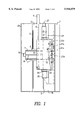
- FIG. 1 is a front view of an embodiment of a numerical controlled router enclosed by a housing of the invention.
- FIG. 2 is a right side view of the numerical controlled router of FIG. 1.
- FIG. 3 is an enlarged partial view of the suction tables of the numerical controlled router of FIG. 2.
- FIG. 4 is a front view of a second embodiment of the invention.
- FIG. 5 is a front view of a third embodiment of the invention.
- FIG. 6 shows an enlarged partial view of a fourth embodiment of the invention.
- a horizontal beam member la is mounted on a support structure 1
- horizontal rails 2 are mounted on a side of the horizontal beam member 1a.
- a horizontally movable member 6 is arranged to ride on rails 2 by bearing means 2a and 2b.
- a screw shaft 3 is provided in a hollowed out portion of the horizontal beam member 1a between the horizontal rails 2. The screw shaft 3 is rotated by a rotating means such as a motor 4, and engages screw engaging member 5 to move member 6 horizontally on the bearings 2a and 2b between rails 2 in a horizontal direction.
- Vertical rails 7 are arranged on a front face of the horizontally movable member 6, a screw shaft 8 is arranged on the horizontally movable member 6 between the vertically arranged rails 7 and is connected to a power transmission member 10 which is rotated by a servomotor 9 mounted near the top of the horizontally movable member 6.
- Bearings 11 are engaged with the vertical rails 7 and a screw engaging member 13 is engaged with the screw shaft 8 arranged in a vertically movable member 12.
- Parallel rails 15 are arranged on a lower surface of a structure supporting member 14 provided on the vertically movable member 12.
- a screw shaft 16 rotatable by a servomotor 17, a screw engaging member 19 is mounted on a head structure 20 to move head structure 20 toward and away from vertically movable member 12 on which it is arranged, by bearing 18 which engages rails 15.
- Heads 21a, 21b, 21c and 21d are arranged on the head structure 20 to be moved by a cylinder 22.
- a housing 23 is supported at the back and sides by the horizontal beam member 1a and at the front and sides by a stretched member 1b of the support structure 1.
- An opening 23a is formed in the housing 23 in front of the head structure 20.
- Bearing members 24 and 25 are mounted on the stretched member 1b, and a rotatable shaft 26 is rotatably supported by bearing members 24 and 25.
- Rotation means 27 is arranged at one end of the rotatable shaft 26 to rotate shaft 26.
- One side of each of two suction tables 31c and 32c are respectively attached to support members 29 and 30 and the rotatable shaft 26 between the support members 29 and 30.
- Rotary supports 33 and 34 are attached to the rotatable shaft 26 near the support members 29 and 30.
- the bases of cylinders 35 and 36 are rotatably attached to the rotary supports 33 and 34, respectfully; the driving shafts 35a and 36a of the cylinders 35 and 36 are attached to support members 31a and 31b near the suction tables 31c and 32c.
- the table supporting members 33 and 34, and the suction tables 31c and 32c are inclined by driving the cylinders 35 and 36.
- the process boards are shown as 31 and 32.
- the one suction table 31c carrying process board 31 is vertically arranged in front of the opening 23a of the housing 23.
- the other table 32c carrying process board 32 is vertically arranged to close the opening 23a of housing 23.
- the one suction table 31c is inclined by driving the cylinder 35 as shown in FIG. 3; a process board 31 is positioned on the suction table 31c when the end of the process board is put on the suction table 31c. Then the cylinder 35 is returned to the original position, and the suction table is vertically positioned.
- the head structure 20 is positioned by driving the servomotors 4 and 9 and moving the horizontally movable member 6 and the vertically movable member 12 and is projected to a predetermined position by the servomotor 17.
- the process board 31 mounted on the suction table 31c by which the opening 23a is closed is machined by projecting the heads 21a to 21d.
- the rotatable shaft 26 is rotated by the rotating means 27, and the other suction table 32c carrying process board 32 is positioned to close the opening 23a by turning.
- the suction table 31c is inclined by driving the rotary cylinder 35; the processed process board is removed from the suction table 31c; a new process board 32 is positioned on the suction table 32c by placing it in contact with the end support 32a of the suction table 32c whereby the new process board on the suction table 32c is ready for processing next.
- the suction table 32c is positioned to close the opening 23a by driving the rotating means 27 and the process board 32 on the suction table 32c is processed by driving the head structure 20 and the heads 21a to 21d.
- the two suction tables 31c and 32c are positioned to close alternately the opening 23a by driving the rotation means 27 and the process boards 31 and 32 mounted on the suction tables 31c and 32c are alternately processed the work time for respectively mounting and machining the two process boards 31 and 32 is shortened and work efficiency is improved. Also, because the two tables 31c and 32c are vertically positioned in the opening 23a, wood chips and dust generated in the machinery fall under the inner suction table and along the housing 23. Therefore, it is not necessary to clean the process board and the inner suction table and the inner portion of the housing 23 may be cleaned at predetermined intervals. A factory in which the numerical control router of the present invention is set is kept clean and is quiet because noise is absorbed by the housing 23.
- Numeric controllers for machining equipment are known.
- the controller is programmed and arranged to operate the positioning means and routing tools in sequence. Since a belt conveyer 37 is set on the stretched member 1b of the support structure 1 and the end of the belt conveyer 37 is projected outside of the housing 23, the fallen wood chips and dust are collected at the outside of the housing 23.
- FIG. 4 shows a front view of a numerical controlled router of a second embodiment of the invention.
- 1 designates a support structure; 2, horizontal rails; 5, a screw shaft; 4, a servomotor; 6, a horizontally movable member; 7, vertical rails; 8, a screw shaft; 10, a connecting member; 12, a vertically movable member; 13, a screw engaging member; 20, a head structure, 21a to 21d, heads; 24 and 25, bearing members; 26, a rotatable shaft; the construction is the same as the embodiment of FIGS. 1, 2 and 3 and the explanation of the construction is therefore omitted.
- rotating means 27 and 28 are attached to the rotary shaft 26, whereby the rotation of the two suction tables 31 and 32 is smoothly accomplished.
- FIG. 5 shows a front view of a numerical controlled router of another embodiment in the invention.
- 1, designates a support structure; 2, horizontal rails; 5, a screw shaft; 4, a servomotor; 6, a horizontally movable member; 7, vertical rails; 8, a screw shaft; 10, a connecting member; 12, a vertically movable member; 13, a screw engaging member; 20, a head structure; 21a to 21d, heads; 24 and 25, bearing members; 26, a rotatable shaft.
- the construction is the same as the above embodiment of FIGS. 1, 2 and 3 and the explanation of the construction is therefore omitted.
- a servomotor 38 having a speed change gear is attached to the rotatable shaft 26 as the rotation means 27 and 28.
- FIG. 6 shows an enlarged partial view of a suction table. 26, designates a rotatable shaft; 31 and 32 are suction tables; this construction is the same as in the above embodiments shown in FIGS. 1, 2 and 3 and the explanation of this construction is therefore omitted.
- the cylinders 35 and 36 for tilting the suction tables 31 and 32 are omitted.
- the suction tables 31c and 32c are so constructed as to be slightly inclined.
- the lower end of the outside suction table is positioned by hand.
- the two suction tables 31c and 32c are fixed on the rotatable shaft 26, to be slightly inclined.
Landscapes
- Engineering & Computer Science (AREA)
- Mechanical Engineering (AREA)
- Milling, Drilling, And Turning Of Wood (AREA)
- Auxiliary Devices For Machine Tools (AREA)
Applications Claiming Priority (2)
| Application Number | Priority Date | Filing Date | Title |
|---|---|---|---|
| JP9180724A JP2913472B2 (ja) | 1997-06-20 | 1997-06-20 | 防塵構造を備えたncルータ |
| JP9-180724 | 1997-06-20 |
Publications (1)
| Publication Number | Publication Date |
|---|---|
| US5944079A true US5944079A (en) | 1999-08-31 |
Family
ID=16088209
Family Applications (1)
| Application Number | Title | Priority Date | Filing Date |
|---|---|---|---|
| US09/018,005 Expired - Fee Related US5944079A (en) | 1997-06-20 | 1998-02-03 | Numerical control router enclosed by a housing |
Country Status (3)
| Country | Link |
|---|---|
| US (1) | US5944079A (de) |
| EP (1) | EP0885689A1 (de) |
| JP (1) | JP2913472B2 (de) |
Cited By (3)
| Publication number | Priority date | Publication date | Assignee | Title |
|---|---|---|---|---|
| US6292998B1 (en) * | 1998-08-07 | 2001-09-25 | w.i.t.—Wiemers innovative Technik GmbH. | Method and apparatus for processing workpieces and assembling and disassembling of structural units |
| US6296599B1 (en) * | 1997-07-29 | 2001-10-02 | Ex-Cell-O Gmbh | Machine-tool |
| US6299393B1 (en) * | 1999-01-15 | 2001-10-09 | The Gleason Works | Method and apparatus for chip removal |
Families Citing this family (2)
| Publication number | Priority date | Publication date | Assignee | Title |
|---|---|---|---|---|
| JP5221296B2 (ja) * | 2008-11-20 | 2013-06-26 | 株式会社平安コーポレーション | サイディングボード加工装置 |
| CN112140242A (zh) * | 2020-08-21 | 2020-12-29 | 衡阳市无量雕塑艺术有限公司 | 一种用于木雕塑的稳定性好的开槽加工平台 |
Citations (5)
| Publication number | Priority date | Publication date | Assignee | Title |
|---|---|---|---|---|
| US4949942A (en) * | 1989-11-13 | 1990-08-21 | Isao Shoda | Table exchanging device for wood working machine |
| US5107910A (en) * | 1991-02-13 | 1992-04-28 | Murakami Iron Works Co., Ltd. | Wood working machine |
| US5323821A (en) * | 1992-12-21 | 1994-06-28 | Heian Corporation | Suction table apparatus of a numerical control router |
| US5564483A (en) * | 1993-10-22 | 1996-10-15 | Scm Group S.P.A. | Unit for machining workpieces, in particular wood |
| US5575318A (en) * | 1995-02-17 | 1996-11-19 | Thermwood Corporation | Slide assembly for machine tools and method of making same |
Family Cites Families (3)
| Publication number | Priority date | Publication date | Assignee | Title |
|---|---|---|---|---|
| US4705438A (en) * | 1986-08-20 | 1987-11-10 | Wesflex International Corporation | Machining center having an inclinable vacuum-holding worktable |
| US5326200A (en) * | 1993-01-05 | 1994-07-05 | Heian Corporation | Press and suction apparatus of a numberical control router |
| SE501849C2 (sv) * | 1993-02-19 | 1995-06-06 | Harry Arnesson | Sätt för bearbetning av ämne av trä, plast, etc. |
-
1997
- 1997-06-20 JP JP9180724A patent/JP2913472B2/ja not_active Expired - Lifetime
- 1997-12-02 EP EP97121177A patent/EP0885689A1/de not_active Withdrawn
-
1998
- 1998-02-03 US US09/018,005 patent/US5944079A/en not_active Expired - Fee Related
Patent Citations (5)
| Publication number | Priority date | Publication date | Assignee | Title |
|---|---|---|---|---|
| US4949942A (en) * | 1989-11-13 | 1990-08-21 | Isao Shoda | Table exchanging device for wood working machine |
| US5107910A (en) * | 1991-02-13 | 1992-04-28 | Murakami Iron Works Co., Ltd. | Wood working machine |
| US5323821A (en) * | 1992-12-21 | 1994-06-28 | Heian Corporation | Suction table apparatus of a numerical control router |
| US5564483A (en) * | 1993-10-22 | 1996-10-15 | Scm Group S.P.A. | Unit for machining workpieces, in particular wood |
| US5575318A (en) * | 1995-02-17 | 1996-11-19 | Thermwood Corporation | Slide assembly for machine tools and method of making same |
Cited By (3)
| Publication number | Priority date | Publication date | Assignee | Title |
|---|---|---|---|---|
| US6296599B1 (en) * | 1997-07-29 | 2001-10-02 | Ex-Cell-O Gmbh | Machine-tool |
| US6292998B1 (en) * | 1998-08-07 | 2001-09-25 | w.i.t.—Wiemers innovative Technik GmbH. | Method and apparatus for processing workpieces and assembling and disassembling of structural units |
| US6299393B1 (en) * | 1999-01-15 | 2001-10-09 | The Gleason Works | Method and apparatus for chip removal |
Also Published As
| Publication number | Publication date |
|---|---|
| JPH1142601A (ja) | 1999-02-16 |
| JP2913472B2 (ja) | 1999-06-28 |
| EP0885689A1 (de) | 1998-12-23 |
Similar Documents
| Publication | Publication Date | Title |
|---|---|---|
| US5564483A (en) | Unit for machining workpieces, in particular wood | |
| JP6821433B2 (ja) | 5軸加工装置 | |
| WO2003097296A1 (en) | Multi-station machining center | |
| JPS6352952A (ja) | 傾斜自在の真空保持ワ−クテ−ブルを有するマシニングセンタ | |
| EP1498368A1 (de) | Plattenbearbeitungseinrichtung | |
| JPH09300149A (ja) | 作業機械 | |
| KR100926342B1 (ko) | 경사 가공이 가능한 복합 가공기 | |
| JPH0919826A (ja) | ホブ盤 | |
| JPS6186145A (ja) | 立横両用型マシニングセンタ | |
| CN217224461U (zh) | 一种对头卧式加工机床 | |
| EP1002620A1 (de) | Werkzeugmaschine mit Schwenktischen | |
| US6033165A (en) | Numerical control router enclosed by a housing | |
| JPH10138001A (ja) | 立旋盤及びその加工システム | |
| JPH0286402A (ja) | 板材の加工機 | |
| JP2001038502A (ja) | Nc旋盤 | |
| EP0885689A1 (de) | Numerisch gesteurter Fräsmaschine von einem Gehäuse umschlossen | |
| JPH0639849Y2 (ja) | 平面加工機 | |
| CA2744986C (en) | Router table with mechanical drive | |
| WO2020214121A1 (en) | Machine performing center hole making process automatically on workpieces cut in fast cutting circular sawing machine | |
| CN112388403B (zh) | 一种数控磨床开齿机 | |
| JP2002254408A (ja) | ドア部材などの加工装置 | |
| KR101881563B1 (ko) | Y축 이송을 구비한 볼 그라인딩 헤드 장치 | |
| KR20040082433A (ko) | 가공품-베어링 스핀들을 구비한 다축 머신닝센터 | |
| JP3706516B2 (ja) | Ncマシンのヘッド支持構造 | |
| JP2501258Y2 (ja) | クランクア―ムの内幅部加工装置 |
Legal Events
| Date | Code | Title | Description |
|---|---|---|---|
| AS | Assignment |
Owner name: HEIAN CORPORATION, JAPAN Free format text: ASSIGNMENT OF ASSIGNORS INTEREST;ASSIGNOR:YAMAUCHI, YOSHIYUKI;REEL/FRAME:008969/0857 Effective date: 19980126 |
|
| REMI | Maintenance fee reminder mailed | ||
| LAPS | Lapse for failure to pay maintenance fees | ||
| STCH | Information on status: patent discontinuation |
Free format text: PATENT EXPIRED DUE TO NONPAYMENT OF MAINTENANCE FEES UNDER 37 CFR 1.362 |
|
| FP | Lapsed due to failure to pay maintenance fee |
Effective date: 20030831 |