EP0885689A1 - Numerisch gesteurter Fräsmaschine von einem Gehäuse umschlossen - Google Patents
Numerisch gesteurter Fräsmaschine von einem Gehäuse umschlossen Download PDFInfo
- Publication number
- EP0885689A1 EP0885689A1 EP97121177A EP97121177A EP0885689A1 EP 0885689 A1 EP0885689 A1 EP 0885689A1 EP 97121177 A EP97121177 A EP 97121177A EP 97121177 A EP97121177 A EP 97121177A EP 0885689 A1 EP0885689 A1 EP 0885689A1
- Authority
- EP
- European Patent Office
- Prior art keywords
- housing
- suction table
- support structure
- numerical control
- horizontal
- Prior art date
- Legal status (The legal status is an assumption and is not a legal conclusion. Google has not performed a legal analysis and makes no representation as to the accuracy of the status listed.)
- Withdrawn
Links
- 238000000034 method Methods 0.000 claims description 20
- 239000000428 dust Substances 0.000 description 3
- 239000002023 wood Substances 0.000 description 3
- 238000010408 sweeping Methods 0.000 description 1
Images


Classifications
-
- B—PERFORMING OPERATIONS; TRANSPORTING
- B23—MACHINE TOOLS; METAL-WORKING NOT OTHERWISE PROVIDED FOR
- B23Q—DETAILS, COMPONENTS, OR ACCESSORIES FOR MACHINE TOOLS, e.g. ARRANGEMENTS FOR COPYING OR CONTROLLING; MACHINE TOOLS IN GENERAL CHARACTERISED BY THE CONSTRUCTION OF PARTICULAR DETAILS OR COMPONENTS; COMBINATIONS OR ASSOCIATIONS OF METAL-WORKING MACHINES, NOT DIRECTED TO A PARTICULAR RESULT
- B23Q11/00—Accessories fitted to machine tools for keeping tools or parts of the machine in good working condition or for cooling work; Safety devices specially combined with or arranged in, or specially adapted for use in connection with, machine tools
- B23Q11/08—Protective coverings for parts of machine tools; Splash guards
-
- B—PERFORMING OPERATIONS; TRANSPORTING
- B23—MACHINE TOOLS; METAL-WORKING NOT OTHERWISE PROVIDED FOR
- B23Q—DETAILS, COMPONENTS, OR ACCESSORIES FOR MACHINE TOOLS, e.g. ARRANGEMENTS FOR COPYING OR CONTROLLING; MACHINE TOOLS IN GENERAL CHARACTERISED BY THE CONSTRUCTION OF PARTICULAR DETAILS OR COMPONENTS; COMBINATIONS OR ASSOCIATIONS OF METAL-WORKING MACHINES, NOT DIRECTED TO A PARTICULAR RESULT
- B23Q11/00—Accessories fitted to machine tools for keeping tools or parts of the machine in good working condition or for cooling work; Safety devices specially combined with or arranged in, or specially adapted for use in connection with, machine tools
- B23Q11/08—Protective coverings for parts of machine tools; Splash guards
- B23Q11/0891—Protective coverings for parts of machine tools; Splash guards arranged between the working area and the operator
-
- Y—GENERAL TAGGING OF NEW TECHNOLOGICAL DEVELOPMENTS; GENERAL TAGGING OF CROSS-SECTIONAL TECHNOLOGIES SPANNING OVER SEVERAL SECTIONS OF THE IPC; TECHNICAL SUBJECTS COVERED BY FORMER USPC CROSS-REFERENCE ART COLLECTIONS [XRACs] AND DIGESTS
- Y10—TECHNICAL SUBJECTS COVERED BY FORMER USPC
- Y10T—TECHNICAL SUBJECTS COVERED BY FORMER US CLASSIFICATION
- Y10T29/00—Metal working
- Y10T29/49—Method of mechanical manufacture
- Y10T29/49998—Work holding
-
- Y—GENERAL TAGGING OF NEW TECHNOLOGICAL DEVELOPMENTS; GENERAL TAGGING OF CROSS-SECTIONAL TECHNOLOGIES SPANNING OVER SEVERAL SECTIONS OF THE IPC; TECHNICAL SUBJECTS COVERED BY FORMER USPC CROSS-REFERENCE ART COLLECTIONS [XRACs] AND DIGESTS
- Y10—TECHNICAL SUBJECTS COVERED BY FORMER USPC
- Y10T—TECHNICAL SUBJECTS COVERED BY FORMER US CLASSIFICATION
- Y10T29/00—Metal working
- Y10T29/51—Plural diverse manufacturing apparatus including means for metal shaping or assembling
- Y10T29/5104—Type of machine
- Y10T29/5105—Drill press
- Y10T29/5107—Drilling and other
-
- Y—GENERAL TAGGING OF NEW TECHNOLOGICAL DEVELOPMENTS; GENERAL TAGGING OF CROSS-SECTIONAL TECHNOLOGIES SPANNING OVER SEVERAL SECTIONS OF THE IPC; TECHNICAL SUBJECTS COVERED BY FORMER USPC CROSS-REFERENCE ART COLLECTIONS [XRACs] AND DIGESTS
- Y10—TECHNICAL SUBJECTS COVERED BY FORMER USPC
- Y10T—TECHNICAL SUBJECTS COVERED BY FORMER US CLASSIFICATION
- Y10T29/00—Metal working
- Y10T29/51—Plural diverse manufacturing apparatus including means for metal shaping or assembling
- Y10T29/5152—Plural diverse manufacturing apparatus including means for metal shaping or assembling with turret mechanism
- Y10T29/5154—Plural diverse manufacturing apparatus including means for metal shaping or assembling with turret mechanism tool turret
-
- Y—GENERAL TAGGING OF NEW TECHNOLOGICAL DEVELOPMENTS; GENERAL TAGGING OF CROSS-SECTIONAL TECHNOLOGIES SPANNING OVER SEVERAL SECTIONS OF THE IPC; TECHNICAL SUBJECTS COVERED BY FORMER USPC CROSS-REFERENCE ART COLLECTIONS [XRACs] AND DIGESTS
- Y10—TECHNICAL SUBJECTS COVERED BY FORMER USPC
- Y10T—TECHNICAL SUBJECTS COVERED BY FORMER US CLASSIFICATION
- Y10T409/00—Gear cutting, milling, or planing
- Y10T409/30—Milling
- Y10T409/30392—Milling with means to protect operative or machine [e.g., guard, safety device, etc.]
-
- Y—GENERAL TAGGING OF NEW TECHNOLOGICAL DEVELOPMENTS; GENERAL TAGGING OF CROSS-SECTIONAL TECHNOLOGIES SPANNING OVER SEVERAL SECTIONS OF THE IPC; TECHNICAL SUBJECTS COVERED BY FORMER USPC CROSS-REFERENCE ART COLLECTIONS [XRACs] AND DIGESTS
- Y10—TECHNICAL SUBJECTS COVERED BY FORMER USPC
- Y10T—TECHNICAL SUBJECTS COVERED BY FORMER US CLASSIFICATION
- Y10T409/00—Gear cutting, milling, or planing
- Y10T409/30—Milling
- Y10T409/304088—Milling with means to remove chip
Definitions
- the present invention relates to a numerical control router enclosed by a housing having an opening for closing by a suction table.
- rails are provided with a horizontal beam supported by a supporting structure on a base, a head structure supported by the rails to move right and left, downward plural head having respectively motors are mounted on the head structure and processing tools as a drill or a cutter are respectively attached to the shaft of motors.
- Table rails are provided with the base downward the heads, a suction table on which a process board is sucked is moved on the rails to the head structure before and behind.
- the numerical control router is not covered by any housing and the suction table is moved under the heads, wood chips and dust are scattered on and near the suction table when the process board is processed. and noise is generated when the process board is processed.
- the primary object of the present invention to provide a numerical control router enclosed by a housing in which chips and dust are shut when a process board is processed.
- the present invention comprises a horizontal move member moving on horizontal rails provided with the side of a support structure, longitudinal move member moving on longitudinal rails provided with the horizontal move member, a head structure mounted on the longitudinal move member, and heads having process tools as a drill and a cutter respectively moved on the head structure by a cylinder before and behind, and is charracterized in that a housing enclosing the surrounding of the horizontal move member, the longitudinal move member and the head structure is supported by the support structure and has an opening before the head structure, a table support member is provided with the support structure in the opening of the housing, a suction table is rotatablly supported on the table support member, and a table rotating cylinder for rotating the suction table has a base member rotatablly connected to the support structure and a moving shaft rotatablly connected to the suction table, whereby a process board is mounded and sucked on the suction table, the opening of the housing closed by rotating the suction table by the table rotating cylinder
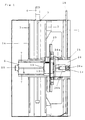
- a horizontal beam member 1a is constructed on a support structure 1, horizontal rails 2 are fixed the side of the horizontal beam member 1a.
- a screw shaft 3 is provided with a hollow portion of the horizontal beam member between the horizontal rails 2 to be rotated by a motor 4, bearings 2a and 2b are engaged with the horizontal rails 2 and a screw engaged member 5 is provided with a horizontal move member 6 between the bearings 2a and 2b.
- Longitudinal rails 7 are provided with the front face of the horizontal move member 6, a screw shaft 8 is provided with the horizontal move member 6 between the longitudinal rails 7 and is connected to a connecting member 10 rotated by a servomotor 9 mounted on the top of the horizontal move member 6.
- Bearings 11 engaged with the longitudinal rails 7 and a screw engaging member 13 engaged with the screw shaft 8 are provided with a longitudinal move member 12.
- Rails 15 are fixed the under surface of a structure supporting member 14 provided with the longitudinal move member 12, a screw shaft 16 provided with the rails 15 in parallel is provided with the structure supporting member 14 to be rotated by a servomotor 17, bearings 18 engaged with rails 15 and a screw engaging member 19 are mounted on a head structure 20, and heads 21a, 21b, 21c and 21d are provided with the head structure 20 to be moved by a cylinder 22.
- a housing 23 is constructed on the horizontal beam member 1a, on the front of a stretched member 1b of the support structure 1 and the side of the horizontal beam member and the stretched member 1b, and a opening 23a of the housing 23 is formed the front of the head structure 20.
- a table supporting member 24 is constructed the end of the stretched member 1b and a suction table 25 is attached to a rotation shaft 25a rotatablly mounted on the table supporting member 24.
- a hollow portion 24a is formed the center of the table supporting member 24, the base member 26a of a table rotating cylinder 26 is rotatablly connected to a cylinder supporting member 1c in the end of the stretched member 1b, a moving shaft 26b of table rotating cylinder 26 is connected to the suction table 25, an upper support 23b in the top of the opening 23a of the housing 23 is attached for stopping the rotation of the suction table 25, an under support 23c is attached to the inside of the table supporting member 24.
- the suction table 25 is horizontally kept by stretching the moving shaft 26a of the table rotating cylinder 26. Therefore, after a process board 27 is put on the suction table 25 by a worker before the suction table 25, when the moving shaft 26b is shortened by driving the table rotating cylinder 26, as shown in Fig. 4, the upper end of the suction table 25 is supported by the upper support 23b and the lower end of the suction table 25 is supported by the under support 23c, whereby the suction table 25 is vertically stood to close all of the opening 23a of the housing 23.
- the head structure 20 is positioned by moving the horizontal move member 6 and the longitudinal move member 12 by driving the servomotor 4 and 9, after the head structure 20 is moved to the predetermined position by the servomotor 17, the process board 27 sucked on the suction table 25 is processed by the heads 21a to 21d horizontally moved by the cylinder 22.
- the processed process board 27 can be easily changed to a new process board by rotating and horizontally keeping the suction table 25.
- the inner portion of the housing 23 may be cleaned every a predetermined interval, a factory in which the numerical control router of the present invnetion is set is kept clean and becomes quiet because noise is absorbed by the housing 23.
Landscapes
- Engineering & Computer Science (AREA)
- Mechanical Engineering (AREA)
- Milling, Drilling, And Turning Of Wood (AREA)
- Auxiliary Devices For Machine Tools (AREA)
Applications Claiming Priority (2)
| Application Number | Priority Date | Filing Date | Title |
|---|---|---|---|
| JP9180724A JP2913472B2 (ja) | 1997-06-20 | 1997-06-20 | 防塵構造を備えたncルータ |
| JP180724/97 | 1997-06-20 |
Publications (1)
| Publication Number | Publication Date |
|---|---|
| EP0885689A1 true EP0885689A1 (de) | 1998-12-23 |
Family
ID=16088209
Family Applications (1)
| Application Number | Title | Priority Date | Filing Date |
|---|---|---|---|
| EP97121177A Withdrawn EP0885689A1 (de) | 1997-06-20 | 1997-12-02 | Numerisch gesteurter Fräsmaschine von einem Gehäuse umschlossen |
Country Status (3)
| Country | Link |
|---|---|
| US (1) | US5944079A (de) |
| EP (1) | EP0885689A1 (de) |
| JP (1) | JP2913472B2 (de) |
Families Citing this family (5)
| Publication number | Priority date | Publication date | Assignee | Title |
|---|---|---|---|---|
| DE19732608B4 (de) * | 1997-07-29 | 2004-04-15 | Ex-Cell-O Gmbh | Werkzeugmaschine |
| DE19934291B4 (de) * | 1998-08-07 | 2004-08-26 | Karl-Heinz Wiemers | Verfahren und Vorrichtung zur mechanischen Bearbeitung von Werkstücken und zur Montage/Demontage von Baugruppen |
| US6299393B1 (en) * | 1999-01-15 | 2001-10-09 | The Gleason Works | Method and apparatus for chip removal |
| JP5221296B2 (ja) * | 2008-11-20 | 2013-06-26 | 株式会社平安コーポレーション | サイディングボード加工装置 |
| CN112140242A (zh) * | 2020-08-21 | 2020-12-29 | 衡阳市无量雕塑艺术有限公司 | 一种用于木雕塑的稳定性好的开槽加工平台 |
Citations (4)
| Publication number | Priority date | Publication date | Assignee | Title |
|---|---|---|---|---|
| EP0257723A1 (de) * | 1986-08-20 | 1988-03-02 | Wesflex International Corporation | Bearbeitungszentrum mit Tisch mit einstellbarer Neigung |
| EP0605940A1 (de) * | 1993-01-05 | 1994-07-13 | Heian Corporation | Numerisch gesteuerte Oberfräsen mit Druck- und/oder Unterdruckmöglichkeiten |
| WO1994019147A1 (en) * | 1993-02-19 | 1994-09-01 | Rosen, Mats | Method for working wood, plastics etc., using a machining centre having an inclinable work table and a chip conveyor |
| EP0650800A2 (de) * | 1993-10-22 | 1995-05-03 | SCM GROUP S.p.A. | Bearbeitungseinheit, insbesondere für Holz |
Family Cites Families (4)
| Publication number | Priority date | Publication date | Assignee | Title |
|---|---|---|---|---|
| US4949942A (en) * | 1989-11-13 | 1990-08-21 | Isao Shoda | Table exchanging device for wood working machine |
| JP2525693B2 (ja) * | 1991-02-13 | 1996-08-21 | 村上鐵工株式会社 | 木工機の自動工具交換装置 |
| US5323821A (en) * | 1992-12-21 | 1994-06-28 | Heian Corporation | Suction table apparatus of a numerical control router |
| US5575318A (en) * | 1995-02-17 | 1996-11-19 | Thermwood Corporation | Slide assembly for machine tools and method of making same |
-
1997
- 1997-06-20 JP JP9180724A patent/JP2913472B2/ja not_active Expired - Lifetime
- 1997-12-02 EP EP97121177A patent/EP0885689A1/de not_active Withdrawn
-
1998
- 1998-02-03 US US09/018,005 patent/US5944079A/en not_active Expired - Fee Related
Patent Citations (4)
| Publication number | Priority date | Publication date | Assignee | Title |
|---|---|---|---|---|
| EP0257723A1 (de) * | 1986-08-20 | 1988-03-02 | Wesflex International Corporation | Bearbeitungszentrum mit Tisch mit einstellbarer Neigung |
| EP0605940A1 (de) * | 1993-01-05 | 1994-07-13 | Heian Corporation | Numerisch gesteuerte Oberfräsen mit Druck- und/oder Unterdruckmöglichkeiten |
| WO1994019147A1 (en) * | 1993-02-19 | 1994-09-01 | Rosen, Mats | Method for working wood, plastics etc., using a machining centre having an inclinable work table and a chip conveyor |
| EP0650800A2 (de) * | 1993-10-22 | 1995-05-03 | SCM GROUP S.p.A. | Bearbeitungseinheit, insbesondere für Holz |
Also Published As
| Publication number | Publication date |
|---|---|
| US5944079A (en) | 1999-08-31 |
| JPH1142601A (ja) | 1999-02-16 |
| JP2913472B2 (ja) | 1999-06-28 |
Similar Documents
| Publication | Publication Date | Title |
|---|---|---|
| EP0650800B1 (de) | Bearbeitungseinheit, insbesondere für Holz | |
| CN213999809U (zh) | 一种适用于木制家具的高效雕刻机 | |
| US6033165A (en) | Numerical control router enclosed by a housing | |
| JP2913472B2 (ja) | 防塵構造を備えたncルータ | |
| KR102402627B1 (ko) | 피가공물 절삭가공시스템 | |
| CN216608383U (zh) | 一种无漆门的边角打磨装置 | |
| JP4527270B2 (ja) | 遊技盤の孔あけ加工装置 | |
| CN213858493U (zh) | 一种衣柜加工用去毛刺装置 | |
| JPH03128203A (ja) | 走行丸のこ盤の集塵装置 | |
| CN209737161U (zh) | 一种机械零部件加工自动清洁除尘台 | |
| CN213592262U (zh) | 一种快速卷帘门加工用切割装置 | |
| JP2546932B2 (ja) | 切断機における集塵装置 | |
| WO2007065134A3 (en) | Method and apparatus for scanning a workpiece through an ion beam | |
| JP5381479B2 (ja) | 基板固定治具及び基板加工装置 | |
| JPH0349833Y2 (de) | ||
| CN220113535U (zh) | 一种门板的开槽设备 | |
| CN218696588U (zh) | 安装在龙门铣床上的清洁装置 | |
| CN221517075U (zh) | 一种立式铣床碎屑防飞溅保护装置 | |
| CN221735559U (zh) | 一种减速机表面加工铣床结构 | |
| SU912522A1 (ru) | Установка дл резки | |
| CN218284164U (zh) | 一种环保型板材机柜的翻转切割装置 | |
| CN223186154U (zh) | 一种金属外观件的自动化雕刻设备 | |
| JPS633769Y2 (de) | ||
| CN220497793U (zh) | 一种立式车床 | |
| CN215356347U (zh) | 一种用于金属切削加工的铣床 |
Legal Events
| Date | Code | Title | Description |
|---|---|---|---|
| PUAI | Public reference made under article 153(3) epc to a published international application that has entered the european phase |
Free format text: ORIGINAL CODE: 0009012 |
|
| AK | Designated contracting states |
Kind code of ref document: A1 Designated state(s): DE IT |
|
| AX | Request for extension of the european patent |
Free format text: AL;LT;LV;MK;RO;SI |
|
| 17P | Request for examination filed |
Effective date: 19990621 |
|
| AKX | Designation fees paid |
Free format text: DE IT |
|
| STAA | Information on the status of an ep patent application or granted ep patent |
Free format text: STATUS: THE APPLICATION IS DEEMED TO BE WITHDRAWN |
|
| 18D | Application deemed to be withdrawn |
Effective date: 20000701 |