US5706083A - Spectrophotometer and its application to a colorimeter - Google Patents
Spectrophotometer and its application to a colorimeter Download PDFInfo
- Publication number
- US5706083A US5706083A US08/769,264 US76926496A US5706083A US 5706083 A US5706083 A US 5706083A US 76926496 A US76926496 A US 76926496A US 5706083 A US5706083 A US 5706083A
- Authority
- US
- United States
- Prior art keywords
- sample
- optical system
- picture
- light
- colorimeter
- Prior art date
- Legal status (The legal status is an assumption and is not a legal conclusion. Google has not performed a legal analysis and makes no representation as to the accuracy of the status listed.)
- Expired - Fee Related
Links
- 238000002798 spectrophotometry method Methods 0.000 claims abstract description 18
- 230000003287 optical effect Effects 0.000 claims description 65
- 238000005259 measurement Methods 0.000 claims description 50
- 239000003086 colorant Substances 0.000 claims description 19
- 230000003595 spectral effect Effects 0.000 claims description 15
- 238000005266 casting Methods 0.000 claims description 4
- 238000013500 data storage Methods 0.000 claims description 4
- 230000000875 corresponding effect Effects 0.000 description 8
- 238000001228 spectrum Methods 0.000 description 8
- 238000000034 method Methods 0.000 description 7
- 238000010586 diagram Methods 0.000 description 5
- 230000001276 controlling effect Effects 0.000 description 4
- 238000012545 processing Methods 0.000 description 4
- 238000012986 modification Methods 0.000 description 3
- 230000008569 process Effects 0.000 description 3
- 238000012937 correction Methods 0.000 description 2
- 238000001914 filtration Methods 0.000 description 2
- 230000004048 modification Effects 0.000 description 2
- 230000004075 alteration Effects 0.000 description 1
- 230000008859 change Effects 0.000 description 1
- 230000002596 correlated effect Effects 0.000 description 1
- 230000007423 decrease Effects 0.000 description 1
- 230000000994 depressogenic effect Effects 0.000 description 1
- 230000006870 function Effects 0.000 description 1
- 238000000926 separation method Methods 0.000 description 1
- 239000000126 substance Substances 0.000 description 1
Images


Classifications
-
- G—PHYSICS
- G01—MEASURING; TESTING
- G01J—MEASUREMENT OF INTENSITY, VELOCITY, SPECTRAL CONTENT, POLARISATION, PHASE OR PULSE CHARACTERISTICS OF INFRARED, VISIBLE OR ULTRAVIOLET LIGHT; COLORIMETRY; RADIATION PYROMETRY
- G01J3/00—Spectrometry; Spectrophotometry; Monochromators; Measuring colours
- G01J3/46—Measurement of colour; Colour measuring devices, e.g. colorimeters
-
- G—PHYSICS
- G01—MEASURING; TESTING
- G01J—MEASUREMENT OF INTENSITY, VELOCITY, SPECTRAL CONTENT, POLARISATION, PHASE OR PULSE CHARACTERISTICS OF INFRARED, VISIBLE OR ULTRAVIOLET LIGHT; COLORIMETRY; RADIATION PYROMETRY
- G01J3/00—Spectrometry; Spectrophotometry; Monochromators; Measuring colours
- G01J3/02—Details
-
- G—PHYSICS
- G01—MEASURING; TESTING
- G01J—MEASUREMENT OF INTENSITY, VELOCITY, SPECTRAL CONTENT, POLARISATION, PHASE OR PULSE CHARACTERISTICS OF INFRARED, VISIBLE OR ULTRAVIOLET LIGHT; COLORIMETRY; RADIATION PYROMETRY
- G01J3/00—Spectrometry; Spectrophotometry; Monochromators; Measuring colours
- G01J3/46—Measurement of colour; Colour measuring devices, e.g. colorimeters
- G01J3/50—Measurement of colour; Colour measuring devices, e.g. colorimeters using electric radiation detectors
- G01J3/502—Measurement of colour; Colour measuring devices, e.g. colorimeters using electric radiation detectors using a dispersive element, e.g. grating, prism
-
- G—PHYSICS
- G01—MEASURING; TESTING
- G01J—MEASUREMENT OF INTENSITY, VELOCITY, SPECTRAL CONTENT, POLARISATION, PHASE OR PULSE CHARACTERISTICS OF INFRARED, VISIBLE OR ULTRAVIOLET LIGHT; COLORIMETRY; RADIATION PYROMETRY
- G01J3/00—Spectrometry; Spectrophotometry; Monochromators; Measuring colours
- G01J3/28—Investigating the spectrum
- G01J3/2803—Investigating the spectrum using photoelectric array detector
- G01J2003/2813—2D-array
-
- G—PHYSICS
- G01—MEASURING; TESTING
- G01J—MEASUREMENT OF INTENSITY, VELOCITY, SPECTRAL CONTENT, POLARISATION, PHASE OR PULSE CHARACTERISTICS OF INFRARED, VISIBLE OR ULTRAVIOLET LIGHT; COLORIMETRY; RADIATION PYROMETRY
- G01J3/00—Spectrometry; Spectrophotometry; Monochromators; Measuring colours
- G01J3/28—Investigating the spectrum
- G01J2003/283—Investigating the spectrum computer-interfaced
-
- G—PHYSICS
- G01—MEASURING; TESTING
- G01J—MEASUREMENT OF INTENSITY, VELOCITY, SPECTRAL CONTENT, POLARISATION, PHASE OR PULSE CHARACTERISTICS OF INFRARED, VISIBLE OR ULTRAVIOLET LIGHT; COLORIMETRY; RADIATION PYROMETRY
- G01J3/00—Spectrometry; Spectrophotometry; Monochromators; Measuring colours
- G01J3/02—Details
- G01J3/0264—Electrical interface; User interface
-
- G—PHYSICS
- G01—MEASURING; TESTING
- G01J—MEASUREMENT OF INTENSITY, VELOCITY, SPECTRAL CONTENT, POLARISATION, PHASE OR PULSE CHARACTERISTICS OF INFRARED, VISIBLE OR ULTRAVIOLET LIGHT; COLORIMETRY; RADIATION PYROMETRY
- G01J3/00—Spectrometry; Spectrophotometry; Monochromators; Measuring colours
- G01J3/02—Details
- G01J3/0267—Sample holders for colorimetry
-
- G—PHYSICS
- G01—MEASURING; TESTING
- G01J—MEASUREMENT OF INTENSITY, VELOCITY, SPECTRAL CONTENT, POLARISATION, PHASE OR PULSE CHARACTERISTICS OF INFRARED, VISIBLE OR ULTRAVIOLET LIGHT; COLORIMETRY; RADIATION PYROMETRY
- G01J3/00—Spectrometry; Spectrophotometry; Monochromators; Measuring colours
- G01J3/02—Details
- G01J3/0278—Control or determination of height or angle information for sensors or receivers
Definitions
- the present invention relates to a spectrophotometer that measures a two-dimensional area or a spot area in a rather broad sample surface.
- a spectrophotometer is used in an area analyzer, in a colorimeter, etc.
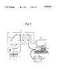
- FIG. 9 A colorimeter using a two-dimensional spectrophotometer is illustrated in FIG. 9.
- Light emitted from a lamp 11 is reflected by the surface of a sample 2 placed on a sample stage 1, and passes through a slit 12 extending in the Y-direction.
- the light passing through the slit 12, which corresponds to a linear portion extending in the Y-direction on the sample surface, is collimated by a lens 13 and is separated with respect to the wavelength by a diffraction grating 14.
- the separated light passes through a harmonics-eliminating filter 15 and is cast on a photo-detector 17 by a lens 16.
- the photo-detector 17 is composed of two-dimensionally-arrayed tiny photo-sensors, where one dimension in the Y-direction corresponds to the linear portion of the sample surface and the other dimension in the ⁇ -direction corresponds to wavelength of the separated light coming from every elementary area of the linear portion. That is, a spectral image representing the collection of the spectra of the linear portion of the sample 2 is cast on the photo-detector 17.
- an optical system 10 including the lamp 11, diffraction grating 14 and photo-detector 17 is moved by a motor (not shown) intermittently in the X-direction, which is perpendicular to the linear portion in the Y-direction, the spectral images of the linear portions are respectively obtained.
- the sample stage 1 may be moved in the X-direction.
- spectra of the elementary areas constituting the two-dimensional area swept by the linear portion on the sample surface are obtained.
- the photo-intensity data constituting the spectra of the two-dimensional area is processed in a personal computer 20 to determine the color of every elementary area. The results of the data processing are shown on the screen of a display device 21 or given out from a printer 22.
- Such a two-dimensional colorimeter or spectrophotometer is useful in measuring a color distribution of a two-dimensional area or in performing a two-dimensional chemical analysis. It should be noted, however, that the operator must determine first the area in which a measurement is performed. In a conventional colorimeter or spectrophotometer, the operator moves the sample stage or the optical system while looking carefully at the sample and the optical system together. When the measurement area is small compared to the whole area of the sample, or when an exact placing of the measurement area is required, such an area setting is tedious and troublesome for the operator.
- An object of the present invention is therefore to provide a spectrophotometer or a colorimeter in which placing of a measurement area is greatly facilitated.
- Further object of the present invention is to provide an advanced form of the above spectrophotometer or a colorimeter in which a preparatory measurement can be made to facilitate the proper measurement or to improve the efficiency of the overall measurement.
- the first type of spectrophotometer according to the present invention includes:
- spectral element for separating the light coming from a linear portion of the sample with respect to wavelength
- a photo-detector including a plurality of elementary photo-sensors arrayed two-dimensionally for measuring the light separated by the spectral element
- a first controller for controlling a relative movement of a sample stage on which the sample is mounted and an optical system including the spectral element and the photo-detector in order to perform a spectrophotometry
- a display device for showing the picture of the sample
- an input device such as a mouse, track ball, digitizer, slide pad, keyboard, etc., used by an operator looking at the picture for designating a place on the sample;
- a second controller for controlling a relative movement of a sample stage and the optical system in order to bring the designated place at the optical system.
- the spectrophotometer may further include:
- a window generator for generating an image of a window at the designated place
- a superimposer for superimposing the image of the window on the picture of the sample.
- a second type of spectrophotometer according to the present invention includes:
- a spectral element for separating the light coming from the sample with respect to wavelength
- a photo-detector for measuring the light separated by the spectral element
- a display device for showing the picture of the sample
- a controller for controlling a relative movement of a sample stage and the optical system in order to bring the designated place at the optical system.
- the spectrophotometer of this type may further include:
- a pointer generator for generating an image of a pointer at the designated place
- a superimposer for superimposing the image of the pointer on the picture of the sample.
- the function of the pointer is just the same as the window in the above spectrophotometer.
- the operator can designate or set a desired measurement area or measurement spot looking at the picture of the sample surface on the display device.
- the window or pointer superimposed on the picture clearly identify the measurement area or spot.
- the second controller in the first type or the controller in the second type moves the sample stage or the optical system according to the movement of the window or the pointer.
- the second controller in the first type or the controller in the second type may move them after the measurement area is finally determined.
- the third type of the present invention is an application to a colorimeter which is used for measuring a color or colors of a sample mounted on a sample stage by performing a spectrophotometry of the sample using an optical system.
- the colorimeter includes:
- a camera for taking a color picture of the sample, the picture consisting of two-dimensionally arrayed pixels
- a data storage for storing color data of the pixels with an information about a place of each of the pixels
- moving means for moving the sample stage and/or the optical system
- a controller for controlling a relative movement of the sample stage and the optical system so that the spectrophotometry is performed on the measurement area.
- the colorimeter may further include:
- a pointer generator for generating an image of a pointer at the designated place
- a superimposer for superimposing the image of the pointer on the picture of the sample.
- the camera takes a color picture of the sample before a proper color measurement using a spectrophotometry is performed.
- the color data of the picture is stored in a data storage.
- the color data may, for example, be separated into red (R), green (G) and blue (B) primary colors, or may be separated otherwise so long as the separation can discriminate different colors of the sample surface.
- the color data is stored with the information about the place of each pixel. Using the color data with the information about the place, various preparatory measures can be taken, one of which is to automatically determine the place and/or the size of a measurement area suited for the object of the color measurement.
- the determining means When, for example, a precise color comparison between two or more areas having the same or similar colors on a sample is required, the determining means read out the color data of the pixels with the information about the place from the data storage, and determine areas of the same or similar colors. Then, referring to a preset rule, the determining means determine the places and/or the sizes of measurement areas on the sample. After the measurement areas are determined, the controller moves the sample or the optical system to bring the measurement areas to the optical system one by one, whereby color measurements by spectrophotometry are automatically performed. When the size of the measurement areas, as well as the places, are determined, the controller changes the distance between the sample and the optical system. If a zoom lens is used, the distance need not be changed but the focal length of the zoom lens is changed to adjust the size of the measurement area.
- the colorimeter of the present invention greatly improves the efficiency of color measurements, and decreases the processing time.
- FIG. 1 is a schematic diagram of a colorimeter of EMBODIMENT 1.
- FIGS. 2A and 2B show examples of display on a display screen.
- FIG. 3 is a schematic diagram of the optical system of EMBODIMENT 2.
- FIG. 4 is a schematic diagram of a colorimeter of EMBODIMENT 3.
- FIG. 5 is a schematic diagram of a colorimeter of EMBODIMENT 4.
- FIG. 6 shows a logical structure of the memory space in an RGB memory of EMBODIMENT 4.
- FIG. 7 shows a logical structure of the memory space in an RGB memory of a variation of EMBODIMENT 4.
- FIG. 8 is shows an example of display on a display screen in EMBODIMENT 4.
- FIG. 9 is a schematic diagram of a conventional colorimeter.
- FIG. 1 shows an abstract structure of a colorimeter embodying the first type of the present invention, in which the optical system 10 is the same as shown in FIG. 9.
- a lamp 30 provided for a sample picturing illuminates the sample 2 at an oblique angle, and a CCD camera 31 takes a picture of the whole or a part of the sample 2.
- the image signal of the sample picture is sent to an image signal processor 32 where the signal is converted to a set of image data and stored in a frame memory provided in it.
- Various image processing may be made on the image data of the sample picture in the image signal processor 32, such as noise filtering, edge emphasis, color correction, etc.
- An image superimposing is also performed here to make a window display as described later.
- the image data processed in the image signal processor 32 is sent to a display device 33 where the picture of the sample surface is shown on the screen of the display device 33.
- a signal corresponding to the operation is sent to a controller 35.
- the controller 35 which is composed of a CPU, ROM, RAM, etc., processes the signal, and generates and sends control signals to the image signal processor 32 and a motor driver 36 according to the operation of the mouse 34, as described later. Responsive to the control signals, the motor driver 36 drives an X-axis motor 37 and Y-axis motor 38 to move a sample stage 1, whereas the designated place of the sample is measured.
- a process of a color measurement on the above colorimeter is now described.
- First a sample 2 is put on the sample stage 1, and the operator adjusts the zoom lens (not shown) of the CCD camera 31 to show the picture of the whole sample 2 on the screen of the display device 33.
- the zoom lens is adjusted to show the part enlarged on the display screen 33.
- the operator operates a keyboard (not shown) of the controller 35 to give a command "freeze the picture".
- the controller 35 receives the command, it stops storing image data to the frame memory in the image signal processor 32, whereby the picture on the display screen 33 is freezed.
- the controller 35 creates image data of a frame including a window.
- the window is a rectangle which will be superimposed on the picture of the sample 2 in the display screen 33.
- the image data of a frame including the window is sent to the image signal processor 32.
- a window of a preset size is placed at the center of the display screen 33.
- the window is moved on the display screen 33 accordingly, and when either of two switches on the mouse 34 is depressed, the size of the window is enlarged or shrunk by a preset amount.
- the image signal processor 32 superimposes the image data of the frame from the controller 35 on the image data stored in the frame memory, whereby the window 41 is shown superimposed on the picture 40 of the sample 2 in the display screen 33, as shown in FIG. 2A.
- the window 41 indicates the area in which a spectrophotometric measurement is performed automatically.
- the operator operates the mouse 34.
- the controller 35 creates the image data of a frame including a window 41 that has the size and location according to the operation of the mouse 34, and sends the image data to the image signal processor 32 at every preset short time interval. Every time the image data comes from the controller 35, the image signal processor 32 superimposes the image data on the image data of the sample picture stored in the frame memory, and refreshes the image on the display screen 33.
- the picture 40 on the display screen 33 is changed as shown in FIG. 2B where only the size and location of the window 41 are changed while the picture 40 of the sample surface is unchanged.
- the controller 35 calculates the X-directional and Y-directional movements of the sample stage 1 based on the signal from the mouse 34, and sends commands to the motor driver 36.
- the motor driver 36 sends driving signals to the X-axis motor 37 and Y-axis motor 38 to move the sample stage 1 according to the movement of the mouse 34.
- the operator After locating the window 41 at a desired place in the sample picture 40 on the display screen 33 using the mouse 34, the operator operates the keyboard or the mouse 34 to give a command for starting a spectrophotometric measurement. Receiving the command, the controller 35 starts a spectrophotometric measurement in the selected area of the sample surface corresponding to the window 41.
- the process of the spectrophotometric measurement is as described before. That is, after a linear portion of the selected area is measured, the sample stage 1 is moved a preset small distance (which is normally set equal to the resolution in the X-direction) by the X-axis motor 37 and the next linear portion neighboring the previous linear portion is measured.
- the data sent to the personal computer 20 is processed and colors of respective elementary areas are determined. While the spectrophotometric measurement is performed, signals from the mouse 34 are ignored. When the spectrophotometric measurement is completed, signals from the mouse 34 are duly processed.
- the window 41 moves in the display screen 33 and the sample stage 1 moves according to the movement of the mouse 34 while the sample picture 40 on the display screen 33 is freezed.
- a modification to such method is that the location of the window 41 is fixed at the center of the display screen 33 and the sample picture is not freezed.
- the sample stage 1 is moved accordingly while the CCD camera 31 takes the picture of the fixed place under the optical system 10.
- the sample picture moves according to the movement of the mouse 34 while the window 41 is fixed at the center of the display screen 33 showing the measurement area.
- sample stage 1 is not moved when the mouse 34 is moved and the window 41 in the display screen 33 moves accordingly.
- the operator depresses a switch on the mouse 34 or clicks on an appropriate command area in the display screen 33 to give a command of "move sample stage".
- the controller 35 calculates the direction and amount of movement of the sample stage 1 referring to the location of the window in the display screen 33, and sends commands to the motor driver 36 to move the sample stage 1 as calculated, whereby the place to be measured corresponding to the window 41 comes under the optical system 10.
- the camera 31 is placed at an oblique angle from the normal to the sample surface in the preceding embodiment, which renders a distorted picture of the sample surface.
- a distortion may not be harmful in locating the window at a desired place but gives a rather odd feeling to the operator. It is therefore preferable to correct the distortion especially when the picture is printed out.
- the spectrophotometer of the present embodiment as shown in FIG. 3 does not render such a distortion.
- a lens 50 and a half-mirror 51 are provided between the sample 2 and the optical system 10 to give half of the light from the sample surface to the camera 31 and the rest half to the optical system 10.
- An alternative is that a full-reflection mirror is placed on the optical path to take the picture of the sample surface, and the full-reflection mirror is displaced from the optical path after the picture is freezed on the display screen 33.
- FIG. 4 shows a colorimeter embodying the second type of the present invention.
- the optical system of the colorimeter includes a lamp 61, an object lens 62, a pinhole plate 63, a diffraction grating 64, a harmonics-eliminating filter 65, another lens 66 and a photo-detector 67.
- the lamp 61 casts a spot light of an adequate diameter onto the sample 2, and the light reflected from the sample surface is focused by the object lens 62 on the pinhole plate 63 to form an image of the sample surface.
- the light of a portion (the measurement spot) of the image passes through the pinhole in the pinhole plate 63, and the light is separated with respect to the wavelength by the diffraction grating 64.
- Harmonics in the separated light are eliminated by the harmonics-eliminating filter 65.
- the separated light is cast by the lens 66 onto the photo-detector 67 which is composed of a plurality of elementary photo-sensors aligned linearly, whereby the spectrum of the measurement spot is obtained.
- the data of the spectrum is sent to a personal computer 20 where the data is analyzed and the result is shown on the screen of a display device 21.
- the sample stage 1 is moved in the X- and Y- directions according to the operation of the mouse 34.
- a "+" cursor or an arrow is used to show the measurement spot on the sample picture shown on the display screen 33.
- the colorimeter of the present embodiment is convenient when color measurements at spots of rather small number are required to perform at high speed. It is also advantageous in that the S/N ratio of the measurement is improved.
- One reason is that the intensity of light cast onto the sample 2 is high because the light from the lamp 61 is concentrated in a narrow spotted area.
- Another reason is that an optical system having a larger numerical aperture can be used because less aberrations of the optical system are expected in collimating a spot area toward the diffraction grating 64 than in collimating a linear area. Thus more light is collected by the optical system to produce a spectrum.
- FIG. 5 shows a colorimeter embodying the third type of the present invention.
- the optical system 10 of the colorimeter of the present embodiment is the same as in EMBODIMENT 1.
- a lamp 30 provided for a sample picturing illuminates the sample 2 at an oblique angle, and a color CCD camera 31 takes a picture of the whole or a part of the sample 2.
- the color image signal of the sample picture is sent to an image signal processor 32 where various image processings are made on the image data of the sample picture in the image signal processor 32, such as noise filtering, edge emphasis, color correction, etc, and the picture is shown on the display screen 33.
- the color image signal of a frame from the CCD camera 31 is converted into a set of color image data composed of R (red), G (green) and B (blue) depth data of respective pixels constituting the frame, and the color image data are stored in an RGB memory 70.
- a controller 35 which is composed of a CPU, ROM, RAM, etc., can read out the data of any pixel of any color stored in the RGB memory 70 by designating the proper address.
- the controller 35 reads out an appropriate data from the RGB memory 70 and examines the data. Based on the examination result, the controller 35 generates commands and sends them to a motor driver 36.
- the sample stage 1 is movable three-dimensionally by an X-axis motor 37, Y-axis motor 38 and Z-axis motor 39, among which X-axis motor 37 and Y-axis motor 38 are for locating a desired place of the sample 2 under the optical system 10, and the Z-axis motor 39 is for setting the measurement area at a desired size.
- a command input device 71 such as a keyboard or mouse is connected to the controller 35.
- the command input device 71 to the controller 35 may be commonly used with that of the personal computer 20, and the display device 33 may also be used commonly with that 21 for the personal computer 20.
- the operator puts the sample 2 on the sample stage 1, and adjusts the zoom lens of the CCD camera 31 to show the whole of the sample 2 on the display screen 33.
- the zoom lens is adjusted to show the part enlarged on the display screen 33.
- the operator operates the command input device 71 of the controller 35 to give a command "memory the data".
- the controller 35 receives the command, it stores the color image data of the frame of the sample picture at that time in the RGB memory 70.
- FIG. 6 shows a logical structure of the memory space in the RGB memory 70.
- the RGB memory 70 includes a main memory 80, an X-axis memory 81 and a Y-axis memory 82.
- the main memory 80 consists of memory cells having a two-dimensional structure corresponding to the frame of the CCD camera 31, where each memory cell stores the color data of a pixel.
- Each memory cell of the main memory 80 has the memory capacity corresponding to the depth of the three primary colors, RGB.
- the X-axis memory 81 consists of memory cells having a linear structure corresponding to the X-coordinate of the main memory 80
- Y-axis memory 82 consists of memory cells having a linear structure corresponding to the Y-coordinate of the main memory 80.
- the color data of a frame is stored in the main memory 80. Since the CCD camera 31 is fixed, the scope of the area on the sample 2 taken by the CCD camera 31 is determined if the position of the sample stage 1 (i.e., X-axis position and Y-axis position) and the position of the zoom lens are determined, whereby the X- and Y-coordinates of any place on the sample surface are determined.
- the unit of coordinates is set equal to the minimum resolution of the spectrophotometric measurement, and if the minimum resolution of the spectrophotometric measurement is equal to the size of a pixel of the CCD camera 31, an address within the main memory 80 corresponds to the unit of coordinates in the scope of the area taken by the CCD camera 31.
- the coordinate values are stored in the X-axis memory 81 and the Y-axis memory 82, whereby any coordinate values of the X-axis and Y-axis are directly obtained by reading out the data from the X-axis memory 81 and the Y-axis memory 82.
- a large memory space 83 is provided to cover the whole range of area that the sample stage 1 can reach.
- each memory cell corresponds to an actual elementary area in the whole range of area, and data of a pixel taken by the CCD camera 31 is directly stored in the corresponding memory cell of the large memory space 83.
- the image data taken by the CCD camera 31 occupies a block 84 in the large memory space 83 as shown in FIG. 7.
- the zoom lens of the CCD camera 31 is adjusted to take a very small area on the sample surface, the image data occupies a very small block 84 in the large memory space 83.
- the colorimeter of the present embodiment can automatically choose said some areas, determine the colors and compare them.
- the color to be compared is set by the operator from the command input device 71, where the color may be designated by the color number or by choosing one from a plurality of color samples.
- the controller 35 reads out data from cell to cell in the RGB memory 70 and examines whether the color of the data is the same or similar to the set color. When data of all the cells are examined, the area of the same or similar colors are chosen.
- the hatched areas 91 and 92 can be regarded having the same or similar colors, and a measurement area should be set within each of the areas 91 and 92.
- the areas 91 and 92 can be automatically selected as described above. After the areas 91 and 92 are thus selected, a rectangular window 93 or 94 for showing the measurement area is set in each of the selected areas 91 and 92, and the coordinates of the windows 93 and 94 are determined.
- the amount of movement of the sample stage 1 in the X- and Y-directions for bringing the window 93 or 94 under the optical system 10 is then calculated, and the amount of movement of the sample stage 1 in the Z-direction is also calculated for equalizing the measurement area to the size of the window 93 or 94.
- the controller 35 sends commands representing the X-, Y- and Z-directional movements to the motor driver 36, which controls respective motors 37, 38 and 39 to bring the starting line (a Y-directional linear portion of one of the windows 93, for example) under the optical system 10.
- the linear portion of the window 93 is measured, and a spectral image of the linear portion is obtained, where one dimension of the spectral image corresponds to the Y-directional position of the linear portion and the other dimension corresponds to the spectrum of each point of the linear portion.
- the sample stage 1 is moved by the X-axis motor 37 in the X-direction to the neighboring linear portion and the same measurement as above is done.
- the spectra of each point in the window 93 i.e., the two-dimensional measurement area
- the motor driver 36 drives the X-, Y- and Z-axis motors 37, 38 and 39 to bring the starting line of the next window 94 under the optical system 10.
- a two-dimensional area is measure in the above description, similar measurement on a small spot area on the sample 2 is also possible. Since, in this case, the size of the spot can be varied by moving the sample stage 1 in the Z-direction, such measurements become possible that an average color of a rather broad spot area is measured, or a color of a narrow spot area of a precise position is measured. Further, a measurement of an area having a complicated shape can also be performed by placing a mask plate having an aperture of such shape between the sample 2 and the optical system 10.
- the optical system 10 may be moved instead of moving the sample stage 1.
Landscapes
- Physics & Mathematics (AREA)
- Spectroscopy & Molecular Physics (AREA)
- General Physics & Mathematics (AREA)
- Spectrometry And Color Measurement (AREA)
- Investigating Or Analysing Materials By Optical Means (AREA)
Applications Claiming Priority (4)
| Application Number | Priority Date | Filing Date | Title |
|---|---|---|---|
| JP35032295A JPH09178565A (ja) | 1995-12-21 | 1995-12-21 | 色彩測定装置 |
| JPH7-350322 | 1995-12-21 | ||
| JPH7-350321 | 1995-12-21 | ||
| JP35032195A JPH09178564A (ja) | 1995-12-21 | 1995-12-21 | 分光測定装置 |
Publications (1)
| Publication Number | Publication Date |
|---|---|
| US5706083A true US5706083A (en) | 1998-01-06 |
Family
ID=26579177
Family Applications (1)
| Application Number | Title | Priority Date | Filing Date |
|---|---|---|---|
| US08/769,264 Expired - Fee Related US5706083A (en) | 1995-12-21 | 1996-12-18 | Spectrophotometer and its application to a colorimeter |
Country Status (2)
| Country | Link |
|---|---|
| US (1) | US5706083A (de) |
| EP (1) | EP0780671A1 (de) |
Cited By (20)
| Publication number | Priority date | Publication date | Assignee | Title |
|---|---|---|---|---|
| US6040907A (en) * | 1997-01-21 | 2000-03-21 | Carl Zeiss Jena Gmbh | Microscope system for the detection of emission distribution and process for operation of the same |
| US6166373A (en) * | 1998-07-21 | 2000-12-26 | The Institute For Technology Development | Focal plane scanner with reciprocating spatial window |
| US20010036309A1 (en) * | 2000-02-04 | 2001-11-01 | Tohru Hirayama | Computer color-matching apparatus and paint color-matching method using the apparatus |
| US20030081216A1 (en) * | 2001-11-01 | 2003-05-01 | Martin Ebert | Graphical user interface for sample positioning |
| US6583879B1 (en) * | 2002-01-11 | 2003-06-24 | X-Rite, Incorporated | Benchtop spectrophotometer with improved targeting |
| WO2003067214A3 (en) * | 2002-02-04 | 2003-10-16 | Ortho Mcneil Pharmaceutical Co | Method and apparatus for obtaining molecular data from a pharmaceutical specimen |
| US6707553B1 (en) * | 1999-08-10 | 2004-03-16 | Minolta Co., Ltd. | Color measuring apparatus |
| US20050213090A1 (en) * | 2002-06-21 | 2005-09-29 | Olympus Corporation | Biomolecule analyzer |
| US20070222992A1 (en) * | 2006-03-22 | 2007-09-27 | Nec Corporation | Color identifying device for identifying colors of reaction surfaces produced by chemical reaction and gas identifying device |
| US20080087114A1 (en) * | 2006-10-13 | 2008-04-17 | Heidelberger Druckmaschinen Ag | Positioning Device for a Color Measuring Head |
| US20120201463A1 (en) * | 2009-10-15 | 2012-08-09 | Suzuki Akemi | Image Analysis Method and Image Analysis Apparatus |
| WO2014066178A1 (en) * | 2012-10-23 | 2014-05-01 | Apple Inc. | High accuracy imaging colorimeter by special designed pattern closed-loop calibration assisted by spectrograph |
| US20140204203A1 (en) * | 2013-01-22 | 2014-07-24 | J. A. Woollam Co., Inc. | Reflectometer, spectrophotometer, ellipsometer or polarimeter system including sample imaging system that simultaneously meets scheimpflug condition and overcomes keystone error |
| TWI512274B (zh) * | 2011-09-27 | 2015-12-11 | Ind Tech Res Inst | 影像式彩色分析儀之校正方法及量測裝置 |
| US20160296118A1 (en) * | 2015-04-13 | 2016-10-13 | Atoptix, Llc | Mobile reflectance optical spectroscopy device and process of using and assembling mobile reflectance optical spectroscopy device |
| JP2016206088A (ja) * | 2015-04-27 | 2016-12-08 | 日本電子株式会社 | 制御装置、制御方法、および分析システム |
| US10859439B1 (en) * | 2012-01-22 | 2020-12-08 | J.A. Woollam Co., Inc. | Reflectometer, spectrophotometer, ellipsometer or polarimeter system including sample imaging system that simultaneously meets scheimpflug condition and overcomes keystone error |
| US11002676B2 (en) | 2018-04-09 | 2021-05-11 | Hunter Associates Laboratory, Inc. | UV-VIS spectroscopy instrument and methods for color appearance and difference measurement |
| US20220268630A1 (en) * | 2021-02-22 | 2022-08-25 | Seiko Epson Corporation | Color measuring system and program |
| US11885738B1 (en) | 2013-01-22 | 2024-01-30 | J.A. Woollam Co., Inc. | Reflectometer, spectrophotometer, ellipsometer or polarimeter system including sample imaging system that simultaneously meet the scheimpflug condition and overcomes keystone error |
Families Citing this family (7)
| Publication number | Priority date | Publication date | Assignee | Title |
|---|---|---|---|---|
| BE1012272A5 (fr) * | 1998-11-06 | 2000-08-01 | Biophotonics Sa | Dispositif et procede de mesure d'images colorees. |
| WO2003029811A1 (en) * | 2001-10-04 | 2003-04-10 | Digieye Plc. | Assessing colour fastiness |
| EP1304553B1 (de) * | 2001-10-19 | 2006-03-15 | Gretag-Macbeth AG | Verfahren und Vorrichtung zur optischen Markierung des Zielbereichs eines Farbmessgeräts auf einer Messfläche |
| ES2214927B1 (es) * | 2001-11-20 | 2005-12-16 | Universitat Politecnica De Catalunya | Dispositivo para la medida del color basado en un camara ccd-rgb convencional. |
| US7508508B2 (en) | 2006-09-19 | 2009-03-24 | Seethrough Ltd. | Device and method for inspecting a hair sample |
| US8111395B2 (en) | 2007-01-05 | 2012-02-07 | Malvern Instruments Ltd | Spectrometric investigation of heterogeneity |
| WO2014076789A1 (ja) * | 2012-11-15 | 2014-05-22 | 株式会社島津製作所 | 分析対象領域設定装置 |
Citations (3)
| Publication number | Priority date | Publication date | Assignee | Title |
|---|---|---|---|---|
| US4844617A (en) * | 1988-01-20 | 1989-07-04 | Tencor Instruments | Confocal measuring microscope with automatic focusing |
| WO1991005360A1 (en) * | 1989-09-26 | 1991-04-18 | The University Of Connecticut | Video pixel spectrometer |
| JPH04106431A (ja) * | 1990-08-28 | 1992-04-08 | Anritsu Corp | カラー画像2値化装置 |
-
1996
- 1996-12-18 US US08/769,264 patent/US5706083A/en not_active Expired - Fee Related
- 1996-12-23 EP EP96309433A patent/EP0780671A1/de not_active Withdrawn
Patent Citations (3)
| Publication number | Priority date | Publication date | Assignee | Title |
|---|---|---|---|---|
| US4844617A (en) * | 1988-01-20 | 1989-07-04 | Tencor Instruments | Confocal measuring microscope with automatic focusing |
| WO1991005360A1 (en) * | 1989-09-26 | 1991-04-18 | The University Of Connecticut | Video pixel spectrometer |
| JPH04106431A (ja) * | 1990-08-28 | 1992-04-08 | Anritsu Corp | カラー画像2値化装置 |
Cited By (37)
| Publication number | Priority date | Publication date | Assignee | Title |
|---|---|---|---|---|
| US6040907A (en) * | 1997-01-21 | 2000-03-21 | Carl Zeiss Jena Gmbh | Microscope system for the detection of emission distribution and process for operation of the same |
| US6166373A (en) * | 1998-07-21 | 2000-12-26 | The Institute For Technology Development | Focal plane scanner with reciprocating spatial window |
| US6707553B1 (en) * | 1999-08-10 | 2004-03-16 | Minolta Co., Ltd. | Color measuring apparatus |
| US20010036309A1 (en) * | 2000-02-04 | 2001-11-01 | Tohru Hirayama | Computer color-matching apparatus and paint color-matching method using the apparatus |
| US6959111B2 (en) * | 2000-02-04 | 2005-10-25 | Kansai Paint Co., Ltd. | Computer color-matching apparatus and paint color-matching method using the apparatus |
| US20030081216A1 (en) * | 2001-11-01 | 2003-05-01 | Martin Ebert | Graphical user interface for sample positioning |
| US6583879B1 (en) * | 2002-01-11 | 2003-06-24 | X-Rite, Incorporated | Benchtop spectrophotometer with improved targeting |
| US6654118B2 (en) * | 2002-02-04 | 2003-11-25 | Ortho-Mcneil Pharmaceutical, Inc. | Method and apparatus for obtaining molecular data from a pharmaceutical specimen |
| WO2003067214A3 (en) * | 2002-02-04 | 2003-10-16 | Ortho Mcneil Pharmaceutical Co | Method and apparatus for obtaining molecular data from a pharmaceutical specimen |
| AU2003212885B2 (en) * | 2002-02-04 | 2007-09-20 | Ortho-Mcneil Pharmaceutical, Inc. | Method and apparatus for obtaining molecular data from a pharmaceutical specimen |
| AU2003212885C1 (en) * | 2002-02-04 | 2008-04-24 | Ortho-Mcneil Pharmaceutical, Inc. | Method and apparatus for obtaining molecular data from a pharmaceutical specimen |
| US20050213090A1 (en) * | 2002-06-21 | 2005-09-29 | Olympus Corporation | Biomolecule analyzer |
| US6980294B2 (en) * | 2002-06-21 | 2005-12-27 | Olympus Corporation | Biomolecule analyzer |
| US20070222992A1 (en) * | 2006-03-22 | 2007-09-27 | Nec Corporation | Color identifying device for identifying colors of reaction surfaces produced by chemical reaction and gas identifying device |
| US7746474B2 (en) * | 2006-03-22 | 2010-06-29 | Nec Corporation | Color identifying device for identifying colors of reaction surfaces produced by chemical reaction and gas identifying device |
| US8395809B2 (en) | 2006-10-13 | 2013-03-12 | Heidelberger Druckmaschinen Ag | Positioning device for a color measuring head |
| US20080087114A1 (en) * | 2006-10-13 | 2008-04-17 | Heidelberger Druckmaschinen Ag | Positioning Device for a Color Measuring Head |
| EP1911588A3 (de) * | 2006-10-13 | 2012-04-04 | Heidelberger Druckmaschinen Aktiengesellschaft | Farbmesskopfpositionierungsvorrichtung |
| US20120201463A1 (en) * | 2009-10-15 | 2012-08-09 | Suzuki Akemi | Image Analysis Method and Image Analysis Apparatus |
| US8705865B2 (en) * | 2009-10-15 | 2014-04-22 | Olympus Corporation | Image analysis method and image analysis apparatus |
| TWI512274B (zh) * | 2011-09-27 | 2015-12-11 | Ind Tech Res Inst | 影像式彩色分析儀之校正方法及量測裝置 |
| US10859439B1 (en) * | 2012-01-22 | 2020-12-08 | J.A. Woollam Co., Inc. | Reflectometer, spectrophotometer, ellipsometer or polarimeter system including sample imaging system that simultaneously meets scheimpflug condition and overcomes keystone error |
| US8988682B2 (en) | 2012-10-23 | 2015-03-24 | Apple Inc. | High accuracy imaging colorimeter by special designed pattern closed-loop calibration assisted by spectrograph |
| KR20150136585A (ko) * | 2012-10-23 | 2015-12-07 | 애플 인크. | 분광기를 이용하여 특수 설계된 패턴 폐루프 보정에 의한 고 정확도의 영상 색도계 |
| KR102117734B1 (ko) | 2012-10-23 | 2020-06-01 | 애플 인크. | 분광기를 이용하여 특수 설계된 패턴 폐루프 보정에 의한 고 정확도의 영상 색도계 |
| CN105209869A (zh) * | 2012-10-23 | 2015-12-30 | 苹果公司 | 由光谱仪辅助的特殊设计的图案闭环校准的高精度成像色度计 |
| WO2014066178A1 (en) * | 2012-10-23 | 2014-05-01 | Apple Inc. | High accuracy imaging colorimeter by special designed pattern closed-loop calibration assisted by spectrograph |
| US20140204203A1 (en) * | 2013-01-22 | 2014-07-24 | J. A. Woollam Co., Inc. | Reflectometer, spectrophotometer, ellipsometer or polarimeter system including sample imaging system that simultaneously meets scheimpflug condition and overcomes keystone error |
| US11885738B1 (en) | 2013-01-22 | 2024-01-30 | J.A. Woollam Co., Inc. | Reflectometer, spectrophotometer, ellipsometer or polarimeter system including sample imaging system that simultaneously meet the scheimpflug condition and overcomes keystone error |
| US20160296118A1 (en) * | 2015-04-13 | 2016-10-13 | Atoptix, Llc | Mobile reflectance optical spectroscopy device and process of using and assembling mobile reflectance optical spectroscopy device |
| US9706927B2 (en) * | 2015-04-13 | 2017-07-18 | Atoptix, Llc | Mobile reflectance optical spectroscopy device and process of using and assembling mobile reflectance optical spectroscopy device |
| JP2016206088A (ja) * | 2015-04-27 | 2016-12-08 | 日本電子株式会社 | 制御装置、制御方法、および分析システム |
| US11002676B2 (en) | 2018-04-09 | 2021-05-11 | Hunter Associates Laboratory, Inc. | UV-VIS spectroscopy instrument and methods for color appearance and difference measurement |
| US11656178B2 (en) | 2018-04-09 | 2023-05-23 | Hunter Associates Laboratory, Inc. | UV-VIS spectroscopy instrument and methods for color appearance and difference measurement |
| US12111258B2 (en) | 2018-04-09 | 2024-10-08 | Hunter Associates Laboratory, Inc. | Instruments and methods for characterizing the appearance of samples |
| US20220268630A1 (en) * | 2021-02-22 | 2022-08-25 | Seiko Epson Corporation | Color measuring system and program |
| US11940327B2 (en) * | 2021-02-22 | 2024-03-26 | Seiko Epson Corporation | Color measuring system and program |
Also Published As
| Publication number | Publication date |
|---|---|
| EP0780671A1 (de) | 1997-06-25 |
Similar Documents
| Publication | Publication Date | Title |
|---|---|---|
| US5706083A (en) | Spectrophotometer and its application to a colorimeter | |
| EP0534948B1 (de) | Zweifarben Kamera Mikroskop sowie Methodologie zur Anfärben von Zellen sowie Analyse | |
| JP3468504B2 (ja) | 測定手順ファイル生成方法、測定装置および記憶媒体 | |
| CN112648926B (zh) | 一种线聚焦彩色共焦三维表面高度测量装置及方法 | |
| US5751420A (en) | Spectropotometer with a field restrictor and its application to a colorimeter | |
| JP3893922B2 (ja) | レンズの評価方法およびレンズ評価装置 | |
| JP2005164612A (ja) | スペクトル画像システムをアライメントする方法、単色サンプル画像を得るための装置及び方法、スペクトル画像システム、並びに中期スプレッド発見装置 | |
| CA2334225C (en) | Method and device for opto-electrical acquisition of shapes by axial illumination | |
| US7583419B2 (en) | System for capturing graphical images using hyperspectral illumination | |
| JP2558864B2 (ja) | 分光解析装置 | |
| US11041799B2 (en) | Device for 3D measurement of object coordinates | |
| DE102019212936A1 (de) | Bildprüfvorrichtung | |
| JPH1198372A (ja) | 色調整方法 | |
| JPH10213635A (ja) | 放射分布検出用顕微鏡システム及びその操作方法 | |
| JPH09178564A (ja) | 分光測定装置 | |
| JPH09133517A (ja) | 分布測定装置 | |
| JPH09178565A (ja) | 色彩測定装置 | |
| US6215588B1 (en) | Infrared microscope | |
| US6147750A (en) | Determination of gloss quality | |
| JPS61247962A (ja) | 細胞診断装置 | |
| JPH0820309B2 (ja) | 分光演算装置 | |
| JPH11271033A (ja) | 三次元形状物体撮像装置 | |
| JP2000180726A (ja) | 赤外顕微鏡 | |
| US5128710A (en) | Instrument for the point-by-point measuring of color originals to be copied | |
| US20230251135A1 (en) | Infrared raman microscope |
Legal Events
| Date | Code | Title | Description |
|---|---|---|---|
| AS | Assignment |
Owner name: SHIMADZU CORPORATION, JAPAN Free format text: ASSIGNMENT OF ASSIGNORS INTEREST;ASSIGNORS:IIDA, ATSUHIRO;YOKOTA, KAZUMI;IKEDA, EIJI;REEL/FRAME:008353/0796 Effective date: 19961205 |
|
| FEPP | Fee payment procedure |
Free format text: PAYOR NUMBER ASSIGNED (ORIGINAL EVENT CODE: ASPN); ENTITY STATUS OF PATENT OWNER: LARGE ENTITY |
|
| FPAY | Fee payment |
Year of fee payment: 4 |
|
| REMI | Maintenance fee reminder mailed | ||
| LAPS | Lapse for failure to pay maintenance fees | ||
| STCH | Information on status: patent discontinuation |
Free format text: PATENT EXPIRED DUE TO NONPAYMENT OF MAINTENANCE FEES UNDER 37 CFR 1.362 |
|
| FP | Lapsed due to failure to pay maintenance fee |
Effective date: 20060106 |