US5634826A - Electrical connector - Google Patents
Electrical connector Download PDFInfo
- Publication number
- US5634826A US5634826A US08/576,018 US57601895A US5634826A US 5634826 A US5634826 A US 5634826A US 57601895 A US57601895 A US 57601895A US 5634826 A US5634826 A US 5634826A
- Authority
- US
- United States
- Prior art keywords
- key
- passages
- electrical connector
- detents
- conduits
- Prior art date
- Legal status (The legal status is an assumption and is not a legal conclusion. Google has not performed a legal analysis and makes no representation as to the accuracy of the status listed.)
- Expired - Lifetime
Links
Images


Classifications
-
- H—ELECTRICITY
- H01—ELECTRIC ELEMENTS
- H01R—ELECTRICALLY-CONDUCTIVE CONNECTIONS; STRUCTURAL ASSOCIATIONS OF A PLURALITY OF MUTUALLY-INSULATED ELECTRICAL CONNECTING ELEMENTS; COUPLING DEVICES; CURRENT COLLECTORS
- H01R13/00—Details of coupling devices of the kinds covered by groups H01R12/70 or H01R24/00 - H01R33/00
- H01R13/40—Securing contact members in or to a base or case; Insulating of contact members
- H01R13/42—Securing in a demountable manner
- H01R13/436—Securing a plurality of contact members by one locking piece or operation
- H01R13/4361—Insertion of locking piece perpendicular to direction of contact insertion
- H01R13/4362—Insertion of locking piece perpendicular to direction of contact insertion comprising a temporary and a final locking position
Definitions
- the invention concerns an electrical connector.
- the invention relates to a connector comprising an insulative material body having rows of passages into each of which is inserted a male or female electrical contact member crimped at one end to an electrical conductor.
- the prior art includes connectors of this kind that include a locking key formed by a U-shaped member with a series of bars upstanding from the center section in corresponding relationship to the rows of passages, the insulative material body including slots perpendicular to the passages into which the bars are inserted so that they bear against a shoulder on the electrical contact members to oppose accidental withdrawal of the latter.
- connectors have various drawbacks. If they are required to include different electrical contact members, i.e. to provide electrical connections with different current ratings, complex casing members and equally complex keys are required, which increases the cost of such connectors.
- a first aim of the invention is to remedy this drawback.
- the electrical connector of the invention comprises an insulative material body having a series of passages disposed in parallel rows and each adapted to receive a male or female electrical contact member crimped to one end of a conductor and having a shoulder partway along its length, the body including slots in the walls separating the rows of passages and conduits near two opposite walls, a key for locking the contact members being provided in the form of a U-shaped member with two branches adapted to be inserted into the conduits and a center section with upstanding therefrom a series of parallel bars adapted to be inserted into the slots and to cooperate with the shoulders of the electrical contact members to lock them in the passages, the slots are perpendicular to the axes of the passages and extend from one of the conduits adapted to receive one branch of the key to the other conduit adapted to receive the other branch, so as to form two lips in each wall separating the rows of passages, the bars having a profile featuring at least one rib facing towards one lip, the latter including a corresponding groove and edges projecting into the passage
- This connector has a simple structure, all the bars being identical; the passages can be adapted to receive electrical contact members having different dimensions but all having the same thinner part at the same height to fit in the gaps between the bars.
- the ribs are on the side facing towards the shoulders of the electrical contact members, the edges projecting into the passages of two adjoining rows being provided on either side of the ribs.
- the link between the lip and the bar confers high mechanical strength which opposes flexing of the bar even if a high traction force is applied to pull out an electrical contact member.
- the key can be fitted only if all the electrical contact members are correctly in place.
- each branch has on its outside face a lug sliding in a slot in the corresponding wall of the body.
- the keys therefore remain attached to the connector bodies and this also facilitates mounting of the electrical contact members in the latter.
- the branches have a boss on each edge near their free end and detents are formed near the ends of the conduits, with which the bosses cooperate, the detents near one end corresponding to a ready position of the key and the detents near the other end corresponding to a locked position of the key.
- each branch has an elongate opening at this point.
- the connector of the invention is adapted to be inserted into a skirt of a complementary member and the body includes a housing in which the center section of the key engages in the locked position.
- the key is perfectly retained and cannot become unlocked when the body is accommodated in the skirt and, moreover, said key opposes assembly of the body and the complementary member if the key is not in the locked position, which it can only occupy if all of the electrical contact members are correctly in place in the passages.
- FIGS. 1 and 2 are perspective views of a locking key for an electrical connector in accordance with the invention.
- FIG. 3 is an elevation view of an electrical contact member adapted to be fitted into the electrical connector of the invention.
- FIG. 4 is a diagrammatic elevation view of the electrical connector of the invention showing the key in the ready position.
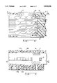
- FIG. 5 is a view in section on the line 5--5 in FIG. 6.
- FIG. 6 is a view in section on the line 6--6 in FIG. 5.
- FIG. 7 is a diagrammatic elevation view of the electrical connector of the invention showing the key when it is not in the locked position.
- FIG. 8 is a view in section on the line 8--8 in FIG. 9.
- FIG. 9 is a view in section on the line 9--9 in FIG. 8.
- FIG. 10 is a view in section on the line 10--10 in FIG. 9.
- FIG. 11 is a part-sectional elevation view of the assembled connector.
- FIG. 12 is a view in section on the line 12--12 in FIG. 13.
- FIG. 13 is a view in section on the line 13--13 in FIG. 12.
- FIG. 14 is a view in section on the line 14--14 in FIG. 13.
- FIGS. 1 and 2 are perspective views of a key 1 adapted to be used in conjunction with a casing 20 of a connector.
- the key is a U-shaped member with two branches 2 and 3 and a center section 4.
- Each branch 2 and 3 has a retaining lug 5 on its outside face near its free end.
- This lug has a step 5a on the side facing away from said free end.
- Each branch 2 and 3 has a boss 6 along each longitudinal edge near the free end and, in line with each boss, an elongate opening 7 to allow each boss 6 to retract elastically.
- a series of bars 8 extends away from the inside surface of the center section 4 and parallel to the branches 2 and 3, each bar having a rectangular section with two shorter sides 8a and 8b and two longer sides 8c and 8d, the longer side 8c having a longitudinal median rib 9.
- the corners of the shorter sides 8a and 8b adjoining the longer side 8d are bevelled to form bevels 11.
- the inside face of the branch 2 carries a protuberance 14 parallel to and coplanar with the bars 8, one face of this protuberance 14 having a bevel 15 corresponding to the bevels 11.
- the inside face of the branch 3 also has a protuberance 14 with a bevel 15.
- the casing 20 of the connector is in the form of a substantially parallelepiped-shaped body with a series of passages 17 and 18 in it each adapted to receive an electrical connection member 21.
- FIG. 3 shows the member 21 to a larger scale. It has an elongate body made from a material that is a good conductor of electricity and has at one end an elastic clamp 23 adapted to grip a complementary male member and at the other end crimping lugs 24 and 25 for gripping an electrical connector.
- the body has a shoulder 27 joined to the part with the lugs 24 and 25 by a narrow part 26 ending in a slightly flared portion 28.
- the member 21 can be various sizes depending on the electrical current to flow through it but the narrow part 26 is always the same, as is the distance between the shoulder 27 and the free end, regardless of the size of the member.
- the passages 17 receive members 21 larger than those inserted into the passages 18.
- Each passage 17 and 18 has at one end an opening 30 into which a member 21 is inserted and at the other end a shoulder 31 for retaining said member 21 with its slot 32.
- the casing 20 is adapted to be inserted into a skirt 35 of a female member 38, upstanding from the back of which are male members 36 adapted to pass through the slots 32 and to be inserted into the elastic clamps 23.
- the casing 20 includes conduits 35 and 36 respectively adapted to receive the branches 2 and 3, each conduit having a slot 37 in which the corresponding lug 5 can slide.
- the key can slide freely in the conduits in the casing but cannot separate from the latter.
- first detents 41 for locking the key in a prelocked position and second detents 42 corresponding to a locked position of the key.
- the bosses 6 can engage with the detents 41 or 42 subject to slight elastic deformation facilitated by the slot 7.
- the bosses 6 are inserted in grooves 43 and 44 in the walls 39 and 40, respectively, between the detents 41 and 42.
- passages 17 and 18 are arranged in series aligned in parallel, each series being separated from the adjacent series by a wall 46 and the face 8c of the bars 8 on the same side as the shoulders 31 projecting across two adjacent rows of passages 17, 18.
- Slots 48 with lips 52 and 53 are formed in the walls 46, parallel to the conduits 35 and 36.
- Slots 50 are formed in the walls adjacent the passages 35 and 36, parallel to the conduits 35 and 36. The slots 48 extend from the conduit 35 to the conduit 36.
- a lip 53 of the slots 48 includes a groove 54 to guide the rib 9.
- the protuberances 14 are inserted in the sloes 50.
- the casing 20 has a housing 55 at one end into which the end of the key 1 including the center section 4 is inserted so that said key does not project beyond the surface of said casing when it is in the locked position.
- FIG. 14 shows that the shorter sides 8b of the bars 8 project into the passages 17 of a first row and their shorter sides 8a project into the passages of a row adjacent said first row. Accordingly, the longer sides 8c operate with the shoulders 27 to oppose withdrawal of the members 21 when they are housed in the passages 17, the bevels 11 accommodating the slightly flared portions 28.
- the electrical contact members 21 are female, but they could be male instead, of course.
Landscapes
- Connector Housings Or Holding Contact Members (AREA)
- Details Of Connecting Devices For Male And Female Coupling (AREA)
- Coupling Device And Connection With Printed Circuit (AREA)
Applications Claiming Priority (2)
| Application Number | Priority Date | Filing Date | Title |
|---|---|---|---|
| FR9500455 | 1995-01-17 | ||
| FR9500455A FR2729507B1 (fr) | 1995-01-17 | 1995-01-17 | Perfectionnements aux connecteurs electriques |
Publications (1)
| Publication Number | Publication Date |
|---|---|
| US5634826A true US5634826A (en) | 1997-06-03 |
Family
ID=9475185
Family Applications (1)
| Application Number | Title | Priority Date | Filing Date |
|---|---|---|---|
| US08/576,018 Expired - Lifetime US5634826A (en) | 1995-01-17 | 1995-12-21 | Electrical connector |
Country Status (6)
| Country | Link |
|---|---|
| US (1) | US5634826A (de) |
| EP (1) | EP0723314B1 (de) |
| JP (1) | JP3400224B2 (de) |
| DE (1) | DE69600062T2 (de) |
| ES (1) | ES2108588T3 (de) |
| FR (1) | FR2729507B1 (de) |
Cited By (6)
| Publication number | Priority date | Publication date | Assignee | Title |
|---|---|---|---|---|
| US5839923A (en) * | 1995-12-22 | 1998-11-24 | The Furukawa Electric Co., Ltd. | Connector with terminal withdrawal stopper |
| US5863224A (en) * | 1995-03-07 | 1999-01-26 | Sumitomo Wiring Systems, Ltd. | Retainer type connector |
| US5893780A (en) * | 1996-01-25 | 1999-04-13 | Connecteurs Cinch, Societe Anonyme | Electrical connector |
| US6352443B1 (en) * | 1999-11-17 | 2002-03-05 | Hirose Electric Co., Ltd. | Lamp socket |
| US20030138996A1 (en) * | 1997-04-25 | 2003-07-24 | Semiconductor Energy Laboratory Co., Ltd. | Semiconductor device and method of fabricating the same |
| US20060052004A1 (en) * | 2004-09-09 | 2006-03-09 | Sumitomo Wiring Systems, Ltd. | Connector and method of assembling it |
Families Citing this family (6)
| Publication number | Priority date | Publication date | Assignee | Title |
|---|---|---|---|---|
| JP3042369B2 (ja) * | 1995-05-22 | 2000-05-15 | 住友電装株式会社 | リテーナ取付構造 |
| AU4881097A (en) * | 1996-11-29 | 1998-06-22 | Whitaker Corporation, The | Electrical connector housing and apparatus for unlocking and locking |
| DE19814107A1 (de) * | 1998-03-30 | 1999-10-07 | Whitaker Corp | Gehäuse für eine elektrische Steckverbinderanordnung mit Kontaktsicherung |
| JP3674948B2 (ja) * | 2001-04-13 | 2005-07-27 | 住友電装株式会社 | コネクタ |
| DE20110509U1 (de) * | 2001-06-27 | 2002-09-05 | Grote & Hartmann | Elektrisches Steckverbindergehäuse aus Kunststoff mit einer Sekundärverriegelungseinrichtung |
| JP6497989B2 (ja) * | 2015-03-13 | 2019-04-10 | 矢崎総業株式会社 | コネクタ |
Citations (7)
| Publication number | Priority date | Publication date | Assignee | Title |
|---|---|---|---|---|
| GB2186748A (en) * | 1986-02-14 | 1987-08-19 | Nissan Motor | Electrical connector |
| DE3705739A1 (de) * | 1986-02-24 | 1987-08-27 | Amp Inc | Elektrische verbinderanordnung |
| EP0417655A1 (de) * | 1989-09-12 | 1991-03-20 | Delphi Automotive Systems Deutschland GmbH | Elektrischer Stecker mit zweifacher Kontaktteilverriegelung |
| US5017163A (en) * | 1989-08-02 | 1991-05-21 | Yazaki Corporation | Terminal engaging apparatus of connector |
| US5100346A (en) * | 1991-03-15 | 1992-03-31 | Cardell Corporation | Micropin connector system |
| DE4325371A1 (de) * | 1992-07-28 | 1994-03-03 | Yazaki Corp | Verbindungsvorrichtung mit mehreren Anschlüssen |
| US5516308A (en) * | 1993-09-01 | 1996-05-14 | Yazaki Corporation | Connector equipped with comb-like terminal locking tool |
-
1995
- 1995-01-17 FR FR9500455A patent/FR2729507B1/fr not_active Expired - Lifetime
- 1995-12-21 US US08/576,018 patent/US5634826A/en not_active Expired - Lifetime
- 1995-12-28 JP JP34335395A patent/JP3400224B2/ja not_active Expired - Lifetime
-
1996
- 1996-01-05 DE DE69600062T patent/DE69600062T2/de not_active Expired - Lifetime
- 1996-01-05 ES ES96400030T patent/ES2108588T3/es not_active Expired - Lifetime
- 1996-01-05 EP EP96400030A patent/EP0723314B1/de not_active Expired - Lifetime
Patent Citations (8)
| Publication number | Priority date | Publication date | Assignee | Title |
|---|---|---|---|---|
| GB2186748A (en) * | 1986-02-14 | 1987-08-19 | Nissan Motor | Electrical connector |
| DE3705739A1 (de) * | 1986-02-24 | 1987-08-27 | Amp Inc | Elektrische verbinderanordnung |
| US5017163A (en) * | 1989-08-02 | 1991-05-21 | Yazaki Corporation | Terminal engaging apparatus of connector |
| EP0417655A1 (de) * | 1989-09-12 | 1991-03-20 | Delphi Automotive Systems Deutschland GmbH | Elektrischer Stecker mit zweifacher Kontaktteilverriegelung |
| US5100346A (en) * | 1991-03-15 | 1992-03-31 | Cardell Corporation | Micropin connector system |
| DE4325371A1 (de) * | 1992-07-28 | 1994-03-03 | Yazaki Corp | Verbindungsvorrichtung mit mehreren Anschlüssen |
| US5356317A (en) * | 1992-07-28 | 1994-10-18 | Yazaki Corporation | Multi-terminal connector |
| US5516308A (en) * | 1993-09-01 | 1996-05-14 | Yazaki Corporation | Connector equipped with comb-like terminal locking tool |
Cited By (7)
| Publication number | Priority date | Publication date | Assignee | Title |
|---|---|---|---|---|
| US5863224A (en) * | 1995-03-07 | 1999-01-26 | Sumitomo Wiring Systems, Ltd. | Retainer type connector |
| US5839923A (en) * | 1995-12-22 | 1998-11-24 | The Furukawa Electric Co., Ltd. | Connector with terminal withdrawal stopper |
| US5893780A (en) * | 1996-01-25 | 1999-04-13 | Connecteurs Cinch, Societe Anonyme | Electrical connector |
| US20030138996A1 (en) * | 1997-04-25 | 2003-07-24 | Semiconductor Energy Laboratory Co., Ltd. | Semiconductor device and method of fabricating the same |
| US6352443B1 (en) * | 1999-11-17 | 2002-03-05 | Hirose Electric Co., Ltd. | Lamp socket |
| US20060052004A1 (en) * | 2004-09-09 | 2006-03-09 | Sumitomo Wiring Systems, Ltd. | Connector and method of assembling it |
| US7204725B2 (en) * | 2004-09-09 | 2007-04-17 | Sumitomo Wiring Systems, Ltd. | Connector and method of assembling it |
Also Published As
| Publication number | Publication date |
|---|---|
| ES2108588T3 (es) | 1997-12-16 |
| DE69600062T2 (de) | 1998-01-22 |
| EP0723314A1 (de) | 1996-07-24 |
| EP0723314B1 (de) | 1997-09-10 |
| FR2729507A1 (fr) | 1996-07-19 |
| JP3400224B2 (ja) | 2003-04-28 |
| DE69600062D1 (de) | 1997-10-16 |
| FR2729507B1 (fr) | 1997-02-21 |
| JPH08255647A (ja) | 1996-10-01 |
Similar Documents
| Publication | Publication Date | Title |
|---|---|---|
| US3971613A (en) | Electrical housing member | |
| US5281168A (en) | Electrical connector with terminal position assurance system | |
| US5002504A (en) | Electrical connector latch construction | |
| US5634826A (en) | Electrical connector | |
| US5928011A (en) | Slide lock position assurance and release lever | |
| US3409859A (en) | Separable electrical connector having rearwardly directed latch fingers | |
| GB2082402A (en) | Electrical connector | |
| US7367837B2 (en) | Connector for flexible flat strip cables | |
| EP0445973B1 (de) | Elektrischer Verbinder mit schleifendem Kontakt | |
| US7780484B2 (en) | Electrical connector having alternative inner housings | |
| US5575685A (en) | Electrical connectors | |
| US3763458A (en) | Terminal retaining connector block | |
| US4444450A (en) | Flat transmission cable connector and housing therefor | |
| US5651704A (en) | Electrical connector with terminal retainer | |
| US5122079A (en) | Multiple conductor cable connector with towers | |
| US4900262A (en) | Lock mechanism for electrical connector | |
| US3417365A (en) | Electrical connector | |
| US5468162A (en) | Locking connector | |
| US5064383A (en) | Multiple conductor cable connector with clip and towers | |
| US5385491A (en) | Electrical connector with flexible terminal latch means and terminal position assurance device | |
| US4447102A (en) | Electrical connector assemblies | |
| US5928014A (en) | Electrical connector having a pair of connector housings | |
| US4090770A (en) | Connector cover construction | |
| KR960012624A (ko) | 전기 케이블 어셈블리 | |
| US5009615A (en) | Terminal assembly with fixed and flexible tab receptacle retainers |
Legal Events
| Date | Code | Title | Description |
|---|---|---|---|
| STCF | Information on status: patent grant |
Free format text: PATENTED CASE |
|
| FEPP | Fee payment procedure |
Free format text: PAYOR NUMBER ASSIGNED (ORIGINAL EVENT CODE: ASPN); ENTITY STATUS OF PATENT OWNER: LARGE ENTITY |
|
| FEPP | Fee payment procedure |
Free format text: PAYOR NUMBER ASSIGNED (ORIGINAL EVENT CODE: ASPN); ENTITY STATUS OF PATENT OWNER: LARGE ENTITY Free format text: PAYER NUMBER DE-ASSIGNED (ORIGINAL EVENT CODE: RMPN); ENTITY STATUS OF PATENT OWNER: LARGE ENTITY |
|
| FPAY | Fee payment |
Year of fee payment: 4 |
|
| REMI | Maintenance fee reminder mailed | ||
| FPAY | Fee payment |
Year of fee payment: 8 |
|
| FPAY | Fee payment |
Year of fee payment: 12 |