US5632307A - Methods for using a high tensile strength reinforcement to repair surface defects in a pipe - Google Patents
Methods for using a high tensile strength reinforcement to repair surface defects in a pipe Download PDFInfo
- Publication number
- US5632307A US5632307A US08/472,014 US47201495A US5632307A US 5632307 A US5632307 A US 5632307A US 47201495 A US47201495 A US 47201495A US 5632307 A US5632307 A US 5632307A
- Authority
- US
- United States
- Prior art keywords
- pipe
- adhesive
- filler material
- state
- convolutions
- Prior art date
- Legal status (The legal status is an assumption and is not a legal conclusion. Google has not performed a legal analysis and makes no representation as to the accuracy of the status listed.)
- Expired - Fee Related
Links
Images


Classifications
-
- F—MECHANICAL ENGINEERING; LIGHTING; HEATING; WEAPONS; BLASTING
- F16—ENGINEERING ELEMENTS AND UNITS; GENERAL MEASURES FOR PRODUCING AND MAINTAINING EFFECTIVE FUNCTIONING OF MACHINES OR INSTALLATIONS; THERMAL INSULATION IN GENERAL
- F16L—PIPES; JOINTS OR FITTINGS FOR PIPES; SUPPORTS FOR PIPES, CABLES OR PROTECTIVE TUBING; MEANS FOR THERMAL INSULATION IN GENERAL
- F16L55/00—Devices or appurtenances for use in, or in connection with, pipes or pipe systems
- F16L55/16—Devices for covering leaks in pipes or hoses, e.g. hose-menders
- F16L55/168—Devices for covering leaks in pipes or hoses, e.g. hose-menders from outside the pipe
- F16L55/175—Devices for covering leaks in pipes or hoses, e.g. hose-menders from outside the pipe by using materials which fill a space around the pipe before hardening
-
- F—MECHANICAL ENGINEERING; LIGHTING; HEATING; WEAPONS; BLASTING
- F16—ENGINEERING ELEMENTS AND UNITS; GENERAL MEASURES FOR PRODUCING AND MAINTAINING EFFECTIVE FUNCTIONING OF MACHINES OR INSTALLATIONS; THERMAL INSULATION IN GENERAL
- F16L—PIPES; JOINTS OR FITTINGS FOR PIPES; SUPPORTS FOR PIPES, CABLES OR PROTECTIVE TUBING; MEANS FOR THERMAL INSULATION IN GENERAL
- F16L55/00—Devices or appurtenances for use in, or in connection with, pipes or pipe systems
- F16L55/16—Devices for covering leaks in pipes or hoses, e.g. hose-menders
- F16L55/168—Devices for covering leaks in pipes or hoses, e.g. hose-menders from outside the pipe
- F16L55/1686—Devices for covering leaks in pipes or hoses, e.g. hose-menders from outside the pipe by winding a tape
Definitions
- the present invention relates to methods for repairing axially extending structures having an internal force directed radially outward therefrom and, more particularly, to methods for repairing and reinforcing pipe in a pipeline which carries gas and/or liquid under pressure. Still more particularly, the invention relates to methods for reinforcing a corroded or otherwise defective section of pipeline without taking the pipeline out of service, or at least minimizing the down time during repair and/or rehabilitation.
- Pipelines for carrying gas or liquid under pressure are ordinarily made of steel in order to withstand the internal pressures required to transport fluids over large distances.
- corrosion of the pipe may eventually occur.
- Pipelines buried in the ground are subject to deterioration from electrolytic and biochemical corrosion, cyclical soil stress, cathodic disbonding, and galvanic corrosion resulting from damp soil and from making pipe attachments, such as valves, from metals which are dissimilar to the steel or other material from which the pipelines are made. Over time, these corrosion mechanisms can cause pits and crevices to form in the pipe.
- the pipeline may be subject to mechanical damage, such as gouging and denting from the machinery used to install the pipeline or to expose, inspect and repair the pipeline after installation. These gouges and/or dents weaken the pipe and may quicken the corrosion process.
- the corroded and gouged regions of a pipeline are typically detected through the use of a "smart pig" or through cathodic surveys. Dented portions of a pipeline may be detected through the use of other conventional "pigs" which determine the clearance in the pipeline as they travel therethrough.
- a reinforcing member is applied to cover the deteriorated area.
- the pipeline is prepared for the application of the reinforcing member by removing any corrosion protection material which may have been applied to the pipeline, cleaning the surface by shot-blasting and applying a primer.
- reinforcing members in the form of a plurality of split steel sleeves are welded or bolted to the pipeline in end to end relationship until the entire deteriorated area of the pipeline has been covered. The pressure of the fluid in the pipeline is then returned to normal and the pipeline is again buried.
- a recently developed technique for reinforcing pipeline involves the application of a high tensile strength material to the pipeline by winding to form a plurality of convolutions around the defective region.
- a high tensile strength material As described in published Canadian patent application No. 2,028,524, the disclosure of which is incorporated by reference herein, the surface of a deteriorated portion of the pipeline is prepared in a conventional manner.
- a filler material is then applied to fill in any dents, gouges and corrosion pitting to provide the pipeline with a smooth outer surface. As instructed in the aforementioned patent application and as practiced in the field, the filler material is permitted to cure to a rigid state before the reinforcement process continues.
- an adhesive is applied over the filler material and over the entire circumference of the pipeline in the region of the defect.
- a coiled band of a high tensile strength composite is wound around the pipeline with a layer of adhesive applied between adjacent convolutions.
- the pipeline can be brought to normal operating pressures once the adhesive has cured to a sufficient strength.
- the installation of the high tensile strength composite in accordance with the foregoing technique does not require any special machinery or equipment and can therefore be performed relatively quickly by unskilled workers having only a moderate degree of training.
- this reinforcement method has on occasion produced inconsistent results in returning the corroded pipeline to its initial burst strength. That is, although this reinforcement method may at times return the pipeline to its initial burst strength, in at least one instance, the use of the same materials and the same steps for installing the high tensile strength composite has resulted in a test pipe which was not adequately reinforced and which therefore burst prior to reaching the nominal burst pressure of the pipe.
- the present invention addresses these need by providing an improved method for repairing a pipe having a defective region in its outer surface defined by at least one cavity extending from the outer surface of the pipe toward the center of the pipe.
- the use of the term “pipe” herein is not intended to be limiting, but rather is merely exemplary. That is, as used herein, the term “pipe” includes storage drums, pressure tanks and canisters, and any other axially extending structure having an internal force directed radially outward therefrom.
- a method according to the invention includes the step of providing a filler material having a workable fluid state and a rigid cured state, and then filling the cavity to at least the outer surface of the pipe with the filler material in the fluid state.
- an excess of filling material is applied to overfill the pipe cavity.
- a plurality of convolutions of a high tensile strength material is wrapped about the pipe to form a coil overlying the filler material.
- the coil is then tightened about the pipe so that the filler material completely fills that portion of the cavity underlying the coil, whereupon the filler material is permitted to cure to the rigid state.
- the coil has a sufficient width to entirely cover the cavity. For wider cavities, a plurality of coils may be arranged adjacent one another on the pipe so that the combined width of the coils covers the cavity.
- the high tensile strength material preferably consists of a band of composite material including a multiplicity of continuous, high tensile strength filaments encapsulated in a resin matrix and extending codirectionally with one another through the resin matrix.
- the composites may be electrically conductive or electrically non-conductive, depending on the particular needs of the end user.
- the filaments are preferably nonmetallic filaments; more preferably glass fibers; and still more preferably, E-type glass fibers due to their low cost.
- Preferred bands of composite material may include a plurality of elastic convolutions having a coiled configuration in a relaxed condition. These bands may be wound about the pipe by deflecting portions of the band to an uncoiled configuration and maneuvering these deflected portions of the band around the pipe, wherein these portions will move back toward the relaxed condition to tighten about the pipe.
- the band of high tensile strength material may define a spiral terminating in an inner end and an outer end and having a plurality of elastic convolutions for encircling and engaging the pipe, each convolution having an inner surface and an outer surface in contact with corresponding surfaces of adjacent convolutions.
- the high tensile strength material may consist of a plurality of individual, continuous, high tensile strength filaments encapsulated in a cured resin matrix and extending through the clock spring spiral parallel to the direction of spiral.
- the elasticity of the convolutions will bias the band into the clock spring spiral with a force greater than the weight of the band so that the band remains in its clock spring spiral when suspended by the outer end of the spiral.
- the step of providing the filler material may also include the step of mixing a base material with an activator capable of reacting with the base material to cure the filler material to a rigid state having a high compressive strength.
- an activator capable of reacting with the base material to cure the filler material to a rigid state having a high compressive strength.
- a variety of curable filler materials may be used; however, filler materials including a curable acrylate base material and a peroxide activator are particularly preferred.
- the step of wrapping the high tensile strength material to form a coil about the pipe may create void spaces between the outer surface of the pipe and the coil.
- the filler material be applied to the outer surface of the pipe adjacent these raised regions before the wrapping step so that the filler material completely fills these void spaces.
- a method according to the present invention may further include the step of applying a layer of an adhesive between adjacent ones of the plurality of convolutions of the band of composite material.
- the adhesive may also be applied between the outer surface of the pipe and a first convolution of the coil.
- Preferred adhesives have an uncured fluid state and a cured adhesive state.
- the adhesive is preferably compatible with the filler material so that the adhesive does not prevent the filler material from curing to the rigid state, and so that the filler material does not prevent the adhesive from curing to the adhesive state.
- Such adhesive preferably is also compatible with the protective coating on the pipeline so that the adhesive does not soften the protective coating and so that the protective coating does not prevent the adhesive from curing to the adhesive state.
- adhesives including mixtures of a curable acrylate and an activator for curing the acrylate are particularly preferred.
- the method of the present invention may be employed to reinforce defective regions in pipelines having bends.
- the wrapping step may include the step of wrapping a plurality of convolutions of the high tensile strength material about the pipe to form a plurality of coils overlying the filler material so that adjacent coils are spaced from one another along the outer radius of curvature of the pipe to thereby define unwrapped regions.
- these unwrapped regions may then be filled with a workable material such as the filler material.
- the methods of the present invention provide a way by which pipelines can be restored to at least their original burst strength on a consistent and reliable basis, while providing improved resistance to further structural deterioration of the pipeline caused by corrosion or external damage. Further, these methods are sufficiently simple that they can be performed in a cost efficient manner by unskilled workers, while minimizing the pipeline down time during repair and/or rehabilitation. Although the invention has been described herein with reference to the repair of pipelines, the methods herein are equally applicable to repair and/or reinforce any axially extending structure having an internal force directed radially outward therefrom.
- FIGS. 1A and 1B are enlarged, highly schematic, partial cross-sectional views of a pipe showing a region of deterioration repaired in accordance with a prior art method
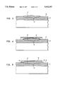
- FIGS. 2-6 are enlarged, highly schematic, partial cross-sectional views of a pipe showing the steps of repairing a region of deterioration in accordance with the present invention
- FIG. 7 is a perspective view of a reinforcement band formed from a high tensile strength material in accordance with the present invention.
- FIG. 8 is a highly schematic side elevation of a reinforcement band being installed around a pipeline in a ditch
- FIG. 9 is an enlarged, highly schematic, partial cross-sectional view of a reinforcement band installed around a pipe having a raised weld bead;
- FIG. 10 is a fragmentary front view of a pipe on which a plurality of reinforcement bands according to the present invention have been installed to provide reinforcement, portions of some of the bands being cut away;
- FIG. 11 is a transverse cross-sectional view taken along line A--A of FIG. 10;
- FIG. 12 is an enlarged fragment of the cross-sectional view of FIG. 11.
- FIG. 13 is a front view of a bent pipe on which a plurality of reinforcement bands according to the present invention have been placed to provide reinforcement.
- the first step in repairing and reinforcing a transmission pipeline is to determine those areas of the pipeline which may be defective as a result of, for example, corrosion, gouging or denting.
- corrosion and gouging are detected by performing cathodic surveys or by sending through the pipeline a so-called "smart pig" which is capable of detecting the presence and location of regions that are corroded or otherwise weakened.
- a clearance "pig” may be passed through the pipeline to determine dented regions of the pipeline. Once these defective regions have been detected, the fluid pressure within the pipeline is reduced substantially below the operating pressure and the soil surrounding the pipeline is excavated to expose these defective regions.
- the pipeline is then prepared for the application of a reinforcement member by removing any corrosion protection and cleaning the surface of all loose material.
- FIGS. 1A and 1B Pipelines reinforced in accordance with this prior art method are shown in FIGS. 1A and 1B.
- a curable filler material 5 is allowed to cure to a rigid state and is then ground or sanded until approximately flush with the outer surface 7 of the pipe.
- the circumference of the pipeline in the defective region, including that area containing the filler material 5, is then coated with an adhesive (not shown), and a coiled band 11 of a high tensile strength composite is wound in a plurality of convolutions around the pipeline with a layer of adhesive between adjacent convolutions.
- the initial steps in reinforcing a pipeline in accordance with the present invention are essentially the same as those of the aforementioned prior art technique. That is, corroded and other weakened areas of the pipeline are detected in the conventional manner through the use of cathodic surveys or smart pigs. After the defective regions have been identified, these areas are exposed by excavating to remove the soil from around the pipeline.
- Pipelines ordinarily are installed with corrosion protection, typically in the form of a coating of coal tar, tape, thin film epoxy, polyethylene, mastic, epoxy paint or polyurethane paint. Should the corrosion protection become damaged, corrosion of the pipeline will normally occur. Before a reinforcement can be applied to the pipeline, the corrosion protection must be removed. This is typically accomplished by chipping and scraping the protective coating from the pipeline. The removal of this protective coating reveals the regions of corrosion which leave the surface of the pipe in a rough, irregular condition.
- pipelines may be mechanically damaged by the heavy machinery used during the installation process or during excavation to make repairs.
- mechanical damage is typically in the form of gouges or dents in the pipeline wall.
- gouging and denting may weaken the pipe itself and the coating of corrosion protection thereabout so that, if left unrepaired, the damaged portion of the pipe may corrode at an advanced rate.
- FIGS. 2-6 A method for reinforcing pipelines in accordance with the present invention is shown in FIGS. 2-6. Following the removal of the protective coating, the method continues by cleaning the surface of the pipeline by wire brushing, sand blasting or other conventional techniques to remove all loose material in the defective region, and the raised edges of any gouges are feathered down by grinding. Optionally, a pretreat bond primer may then be applied to the gouges, dents and areas of pitting caused by corrosion.
- a filler material 12 is applied over the defective region to completely fill in, and in fact to overfill, any pits, gauges or dents, such as cavity 14.
- a suitable filler material will initially have a pasty fluid consistency so that it can be readily applied and worked into cavity 14, and so that it will adhere to cavity 14 once applied.
- the filler material 12 must maintain this workable consistency for a sufficient length of time for the reinforcement process to be completed, after which it will cure or harden to a rigid state. In this rigid state, the filler material should have a sufficient compressive strength to withstand the load which will be transferred through the filler material from the pipe to the reinforcement band. Filler materials having compressive strengths of at least 9,000 psi as measured by ASTM D695 are particularly desirable.
- suitable filler materials will also be compatible with the adhesives used in the installation process of the present invention.
- the term "compatible” refers to filler materials which will completely cure to a rigid state in contact with such adhesives, and which will not interfere with the curing of such adhesives to their full adhesive state.
- a particularly preferred filler material 12 in accordance with the present invention is MA441, produced by Illinois Tool Works of Chicago, Ill. This filler material is a two component system consisting of a methyl methacrylate base component filled with an essentially inert material, such as glass beads, and a peroxide activator for curing the base component.
- the filler material 12 is applied not only to fill cavity 14, but preferably so that it extends above the outer surface 16 of the pipe 10. While the filler material 12 is in its uncured workable state, a layer of an adhesive 18 may be applied by paint roller, brush or other conventional method to the entire outer circumference of the pipe 10 in the defective region, including that region containing filler material 12, as shown in FIG. 4.
- Preferred adhesives will initially be fluid in an uncured state with an appropriate viscosity for easy application and adherence to the pipeline.
- preferred adhesives will be compatible with the protective coating which may remain as a film on the pipeline. In that regard, such preferred adhesives will not soften the protective coating material and will not be prevented from curing to the adhesive state by the protective coating material.
- the adhesive will remain in this uncured fluid state for a sufficient length of time to complete the installation process, after which it will cure to a harder, more strongly adhesive state.
- Particularly preferred adhesives in the cured state will provide protection against ultraviolet radiation, and will exhibit long term resistance to creep at the temperatures at which the pipeline operates, as well as resistance to water absorption and degradation from environmental exposure over long periods of time.
- such adhesives will have a lap shear strength of at least about 900 psi as determined by ASTM D1002, a nominal elongation of about 30%, and a pot life of about 45 minutes in a temperature range of about 32°-110° F. before gelling begins and the adhesive is no longer workable.
- a particularly preferred adhesive in this regard is MA440, produced by Illinois Tool Works of Chicago, Ill.
- This adhesive is a two component system consisting of a methyl methacrylate base component and a peroxide catalyst.
- the MA440 adhesive and the MA441 filler material are compatible with one another such that neither one interferes with the curing of the other to its final cured state.
- reinforcement band 20 is installed around the outer surface of pipe 10 over the defective region.
- reinforcement band 20 is a web of a composite material having a rectangular cross-section, an inner surface, an outer surface, and sides or edges.
- the band 20 is coiled into a spiral having a plurality of concentric elastic convolutions including an innermost convolution having an inner end 30, an outermost convolution having an outer end 32, and intermediate convolutions.
- Methods for fabricating reinforcement band 20 are generally disclosed in U.S. Pat. No. 4,700,752 to Fawley. Preferred methods for fabricated reinforcement band 20 are disclosed in U.S. patent application Ser. No.
- the composite material includes a large plurality of individual, lightweight, high tensile strength fibers encapsulated in a cured resin matrix and extending parallel to one another in the direction of the spiral. Although the parallel fibers are generally indicated by parallel longitudinal lines 34 in FIG. 7, each space between adjacent parallel lines 34 actually represents hundreds or thousands of longitudinal fibers, each having a diameter of less than about 0.001 inches.
- the fibers preferably are nonmetallic and electrically non-conductive, although the use of electrically conductive fibers, such as carbon or graphite fibers, is not prohibited.
- Preferred fibers in this regard are glass fibers, with E-type glass fibers being particularly preferred due to their relatively low cost.
- fibers formed from other high tensile strength materials such as S-type glass and Kevlar, may be used.
- Suitable resins for forming the composite web are elastic when cured, thereby exhibiting an elastic memory.
- these resins are cured in a coiled configuration, such as that of reinforcement band 20, a force can be used to uncoil the band, but once this force is removed the band will return substantially to its initial coiled configuration.
- the elasticity of the convolutions is preferably such that the band is biased into the coiled configuration with a force greater than the weight of the band so that the band will remain in the coiled configuration when suspended by outer end 32.
- the cured resin will be resistant to degradation from moisture, the chemical activity of soil and other environmental activity so as to protect the embedded fibers and the portion of the pipe 10 underlying the reinforcement band 20 from corrosion.
- the resin may be electrically non-conductive or may be made electrically conductive by incorporating an electrically conductive material therein, all depending upon the needs of the end user.
- Suitable resin materials for forming the composite web include polyester resins, polyurethane resins and epoxy resins. Isophthalic polyester resins are particularly preferred.
- a layer of adhesive 18 may be applied directly to the surface of pipe 10 and filler material 12 before the installation of reinforcement band 20.
- this adhesive layer may be applied as an additional protective layer to assure that moisture cannot penetrate and initiate corrosion between the pipe 10 and reinforcement band 20.
- the adhesive will not adhere or will not strongly adhere to the corrosion protection material originally in place on the pipe 10. Indeed, the adhesive may actually react with and soften the corrosion protection material. Therefore, where it is difficult or impossible to completely remove the layer of corrosion protection material from pipe 10 prior to reinforcement, and where the adhesive is not compatible with the corrosion protection material, a barrier film to which the adhesive will strongly adhere is applied around the protective material on pipe 10.
- barrier films may include, for example, conventional shrink wraps, Trenton wax and the like.
- an adhesive pad 36 having a contact adhesive on both sides, is attached to pipe 10 adjacent cavity 14, in the circumferential portion of pipe 10 containing cavity 14.
- a suitable adhesive pad 36 may be a rectangularly shaped close cell vinyl pad with dimensions of about 3.50 inches by about 9.25 inches.
- FIG. 8 shows a reinforcement band 20 being installed on a pipe 10 which is a part of a pipeline.
- the soil surrounding the portions of the pipeline which require reinforcement has been excavated to form a ditch 38 which is large enough so that there is sufficient clearance to maneuver the reinforcement band 20 around the pipeline.
- No cranes or other equipment are required to move the reinforcement bands 20 to the pipeline or to support the bands during installation.
- the reinforcement bands 20 can be carried and positioned manually, usually by one person. For example, the weight of a reinforcement band 20 for a 16 inch diameter pipe is about 14 pounds, and for a 30 inch diameter pipe, the weight is about 29 pounds.
- the reinforcement band 20 is initially applied to pipe 10 by adhering outer end 32 to adhesive pad 36 adjacent cavity 14. This is shown clearly in FIG. 12. With outer end 32 held in place, the reinforcement band 20 may be installed by moving the band under and then over the pipe 10, uncoiling the spiral as it is moved around the pipe. After the first convolution has been applied to the pipe 10, the outer surface of the convolution is coated with adhesive 18 and the reinforcement band 20 is again passed under and then over pipe 10 to form the next convolution. Again, the outer surface of this convolution is coated with adhesive 18 and the next convolution is formed, the process continuing until, as shown in FIG.
- Coil 40 will preferably include at least 5 convolutions, and more preferably about 8 convolutions, of reinforcement band 20.
- FIG. 8 shows the reinforcement band 20 being installed by a single person, a two-person team is preferred since each person can pass the band over or under the pipe 10 to the other person during installation. In addition, one person can hold the remaining portion of band 20 and maintain tension in the convolution being applied to the pipe 10 to assure a tight fit, while the other person applies the coating of adhesive 18 to the external surface of the convolution.
- the convolutions of reinforcement band 20 are wrapped around pipe 10, the elasticity of the composite web will cause the convolutions to tighten somewhat upon themselves and upon the outer surface of pipe 10, thereby causing a portion 42 of filler material 12 to squeeze outwardly from beneath the side edges of coil 40.
- the convolutions are radially aligned with one another by tapping on the side edges with a block or the like until the edges on each side of coil 40 are in substantial alignment with one another.
- the convolutions of coil 40 may then be tightened further by mechanical means until the innermost convolution of coil 40 is in intimate contact with outer surface 16 of pipe 10.
- a Velcro pad is secured to the outermost convolution of coil 40 adjacent end 30.
- a cinch bar (not shown) can then be used to exert a tangential force on the outermost convolution of coil 40.
- the cinch bar consists of a rigid elongated bar having a strap attached at one end thereto. The free end of the strap is provided with a Velcro pad for mating with the Velcro pad adhered to the coil 40.
- one end of the cinch bar is placed against the coil 40 and acts as a fulcrum for the application of a leverage force at the other end of the cinch bar.
- the layer of adhesive 18 between adjacent convolutions acts as a lubricant to facilitate the tightening of the convolutions.
- the innermost convolution comes closer and closer to the outer surface 16 of pipe 10 and additional amounts of filler material 12 are squeezed out from under the side edges of coil 40.
- the tightening process is completed when the innermost convolution of coil 40 is in intimate and substantially continuous contact with the outer surface 16 of pipe 10, as shown in FIG. 6. At this point, there are no void spaces between filler material 12 and the innermost convolution of coil 40. It is not necessary to coat the final convolution of coil 40 with adhesive.
- One or more strips of tape for example, fiber tape, are placed around the coil 40 to hold the coil tightly in place until the adhesive 18 cures.
- a layer of a corrosion protection material 45 can be applied over the coil 40, encapsulating the coil and the adjacent portion of pipe 10.
- Corrosion protection material 45 may be a conventional shrink wrap, tape, mastic, wax or similar material which will serve as a moisture barrier to prevent further corrosion of pipe 10 in the repaired area.
- the pressure within the pipeline can be returned to normal operating pressures.
- the filler material 12 is also curing so that, by the time the pressure in pipe 10 is increased, the filler material will have achieved a rigid state having sufficient compressive strength to transfer the load from pipe 10 to coil 40.
- pipe 10 may include a longitudinal weld bead 44 at the seam where the edges of the sheet of steel have been joined together to fabricate the pipe.
- this weld is formed by double submerge arc welding, and results in a weld bead 44 which is raised above the surface 16 of pipe 10.
- void spaces 46 and 48 will be created between the outer surface 16 of the pipe and the reinforcement band.
- filler material 12 is applied to the outer surface 16 of the pipe on either side of the raised weld bead 44 or similar raised surface irregularity so that, as the reinforcement band 20 is installed to form a coil 40 about the pipe, these void spaces 46 and 48 will be filled with filler material. As coil 40 is tightened, the filler material will spread throughout and entirely fill the void spaces 46 and 48.
- the width of reinforcement band 20 will normally be selected so that it forms a coil 40 which is about two inches wider than cavity 14 so as to completely cover cavity 14; reinforcement bands having a width of about 10-12 inches are typical.
- a number of reinforcement bands 20 may be installed on the pipe to form a plurality of coils 50, 52, 54, 56 and 58 which entirely cover the defective region, as shown in FIG. 10.
- Each of coils 50-58 are formed as described in connection with the formation of coil 40. Although coils 50-58 are shown as abutting one another in edge-to-edge fashion, it is not essential that the coils be in actual contact. Rather, the pipeline will be adequately reinforced even with coils 50-58 installed with small gaps therebetween.
- the pipe When new, the pipe has sufficient burst strength to sustain this hoop stress. However, as it corrodes, the burst strength of the pipe will diminish until it reaches a level at which is can no longer sustain the hoop stress generated under normal operating pressures. The exertion of further internal pressure will initially cause the pipe to deform plastically by bulging, and will eventually result in the pipe rupturing.
- the reinforcement In techniques for reinforcing defective regions of the pipeline, the reinforcement is intended to assume part or all of the hoop stress normally sustained by the pipe. That is, as the pipe expands under the internal fluid pressure, this load will be transferred to the reinforcement which, since it has a relatively low modulus of elasticity, will not expand and will thus prevent the pipe from expanding further.
- the filler material is cured to a rigid state and ground down substantially flush with the outer surface of the pipe before applying the reinforcement band.
- the inconsistent results achieved with this reinforcement method can be attributed to this filler material application and grinding step. That is, in attempting to grind the filler material smoothly, the unskilled workers rehabilitating the pipeline would sometimes grind away a small excess of filler material, resulting in the formation of one or more gaps 13 between the filler material and the reinforcement band, as can be seen in FIG. 1A.
- too little filler material may be ground away, resulting in the formation of gaps 15 between the filler material and the reinforcement band, as shown in FIG. 1B.
- the pipe 10 will be able to expand through the volume of gap 13 on the one hand and gaps 15 on the other hand until contacting and being restrained by the reinforcement band 11. This small amount of expansion of pipe 10 may be sufficient for pipe 10 to fail by bursting.
- the method described above for reinforcing a pipeline can be applied to repair and reinforce pipelines having gouges, dents or corrosion pitting along these bends.
- the radius of curvature of the pipeline will prevent a plurality of coils from being installed in edge-to-edge contact with one another in these curved regions.
- the radius of curvature of the curved region 100 of the pipeline is such that significant gaps 102 and 104 will be extant on the outer radius of curvature of the pipeline between coils 110, 112 and 114, respectively.
- Gaps 102 and 104 will be present even in those cases where the edges of coils 110, 112 and 114 contact one another along the inner radius of curvature of the pipeline.
- the size of these gaps 102 and 104 can be minimized by making the width of coils 110, 112 and 114 as small as practical without detrimentally affecting the installation and function of the reinforcement.
- the optimum width of the coils will depend on the diameter of the pipeline and the radius of curvature of the bend. For example, for 12-18 inch pipelines having bends of about 90°, coils formed from reinforcement bands about 3-6 inches wide are preferred.
- the gaps 102 and 104 between the coils may be filled with a workable sealant or another workable material, such as filler material 12, in order to seal the edges of coils 110, 112 and 114 so that moisture cannot penetrate between the convolutions of the coils.
Landscapes
- Engineering & Computer Science (AREA)
- General Engineering & Computer Science (AREA)
- Mechanical Engineering (AREA)
- Pipe Accessories (AREA)
- Lining Or Joining Of Plastics Or The Like (AREA)
- Blast Furnaces (AREA)
Priority Applications (1)
| Application Number | Priority Date | Filing Date | Title |
|---|---|---|---|
| US08/472,014 US5632307A (en) | 1992-09-09 | 1995-06-06 | Methods for using a high tensile strength reinforcement to repair surface defects in a pipe |
Applications Claiming Priority (3)
| Application Number | Priority Date | Filing Date | Title |
|---|---|---|---|
| US94273192A | 1992-09-09 | 1992-09-09 | |
| US34451394A | 1994-11-23 | 1994-11-23 | |
| US08/472,014 US5632307A (en) | 1992-09-09 | 1995-06-06 | Methods for using a high tensile strength reinforcement to repair surface defects in a pipe |
Related Parent Applications (1)
| Application Number | Title | Priority Date | Filing Date |
|---|---|---|---|
| US34451394A Continuation | 1992-09-09 | 1994-11-23 |
Publications (1)
| Publication Number | Publication Date |
|---|---|
| US5632307A true US5632307A (en) | 1997-05-27 |
Family
ID=25478509
Family Applications (1)
| Application Number | Title | Priority Date | Filing Date |
|---|---|---|---|
| US08/472,014 Expired - Fee Related US5632307A (en) | 1992-09-09 | 1995-06-06 | Methods for using a high tensile strength reinforcement to repair surface defects in a pipe |
Country Status (11)
| Country | Link |
|---|---|
| US (1) | US5632307A (fr) |
| EP (1) | EP0659255B1 (fr) |
| CN (1) | CN1043168C (fr) |
| AT (1) | ATE189736T1 (fr) |
| AU (1) | AU666589B2 (fr) |
| CA (1) | CA2142816C (fr) |
| DE (1) | DE69327847T2 (fr) |
| ES (1) | ES2143510T3 (fr) |
| RU (1) | RU2108514C1 (fr) |
| SA (1) | SA93140300B1 (fr) |
| WO (1) | WO1994005945A1 (fr) |
Cited By (50)
| Publication number | Priority date | Publication date | Assignee | Title |
|---|---|---|---|---|
| WO2000056831A1 (fr) * | 1999-03-19 | 2000-09-28 | Henkel Kommanditgesellschaft Auf Aktien | Etancheite des conduites et necessaire de reparation |
| US6247499B1 (en) | 1999-08-13 | 2001-06-19 | Ico, Inc. | Pipe wrap corrosion protection system |
| WO2001046612A1 (fr) * | 1999-12-20 | 2001-06-28 | Wil-Cor, Inc. | Systeme composite d'enrobage a haute temperature |
| US6298882B1 (en) * | 1999-04-26 | 2001-10-09 | Spm, Inc. | Explosion resistant blanket for flow line |
| US6306781B1 (en) | 1999-07-21 | 2001-10-23 | Senior Investments Ag | Expansion joint patch apparatus |
| US6354334B1 (en) * | 2000-02-25 | 2002-03-12 | Fernand Ellyin | Fiber-reinforced composite wrapped steel liner |
| US6386236B1 (en) | 2000-05-31 | 2002-05-14 | Air Logistics Corporation | Method of prestressing and reinforcing damaged cylindrical structures |
| US6435218B2 (en) * | 2000-02-22 | 2002-08-20 | Mannesmann Ag | Pipe with crack stopper feature, and process of protecting a pipe against propagation of cracks |
| US20020129860A1 (en) * | 2001-03-16 | 2002-09-19 | Manzon Paul Stephen | Local degraded area repair and restoration component for pressure retaining items |
| EP1298267A1 (fr) * | 2000-06-29 | 2003-04-02 | Nippon Oil Corporation | Procede de renfort de structure, materiau contenant des fils de fibre de renfort destine au renfort de structure, materiau de renfort de structure et structure renforcee |
| US20030090106A1 (en) * | 2001-11-09 | 2003-05-15 | Goddard James B. | Pipe having a water-tight in-line bell |
| US20040231740A1 (en) * | 2001-08-07 | 2004-11-25 | Jerome Stubler | Method for repairing pipes |
| US20040231789A1 (en) * | 2003-04-28 | 2004-11-25 | Richard Blackmore | Tensioned pipe support |
| US20060118191A1 (en) * | 2004-12-03 | 2006-06-08 | Rice Brian L | System and method for pipe repair |
| US20060272724A1 (en) * | 2005-04-26 | 2006-12-07 | Borland Robin N | System and method for pipe repair using fiber wrap and polymeric resin |
| US20070107791A1 (en) * | 2004-12-03 | 2007-05-17 | Illinois Tool Works Inc. | System and method for pipe repair |
| US20070169829A1 (en) * | 2006-01-23 | 2007-07-26 | Prabhat Krishnaswamy | Soft crack arrestors for pipelines |
| US20080017263A1 (en) * | 2004-12-03 | 2008-01-24 | Robinson David P | System and method for pipe repair |
| WO2008027649A1 (fr) * | 2006-08-29 | 2008-03-06 | Conocophillips Company | Tuyau enrobé de fibre sèche |
| US20080281178A1 (en) * | 2007-03-07 | 2008-11-13 | Echo Therapeutics, Inc. | Transdermal analyte monitoring systems and methods for analyte detection |
| US20090095796A1 (en) * | 2007-10-16 | 2009-04-16 | Amit Prakash | Wire wrapped pressure vessels |
| US20090295149A1 (en) * | 2008-05-30 | 2009-12-03 | William Zepp | Pipe Joint and Related Method |
| US20090314409A1 (en) * | 2008-06-18 | 2009-12-24 | Ehsani Mohammad R | Apparatus and Method of Reinforcing a Conduit or Vessel |
| US20100000621A1 (en) * | 2008-06-27 | 2010-01-07 | Fujifilm Corporation | Method for repairing flexible tube |
| US7673655B1 (en) | 2008-12-02 | 2010-03-09 | Tdw Delaware, Inc. | Composite wrap repair of internal defects |
| US20100078118A1 (en) * | 2008-09-19 | 2010-04-01 | Ehsani Mohammad R | Repair and strengthening of small diameter pipes with frp laminates |
| US20100084038A1 (en) * | 2006-01-23 | 2010-04-08 | Prabhat Krishnaswamy | Soft Crack Arrestors for Pipelines |
| US20100147409A1 (en) * | 2007-01-15 | 2010-06-17 | Beijing Safetech Pipeline Co., Ltd. | Technique for repairing, strengthening and crack arrest of pipe |
| US20100154913A1 (en) * | 2008-02-08 | 2010-06-24 | Brooks Carl M | Repair apparatus and method for pipe and fittings |
| US20100326737A1 (en) * | 2009-06-24 | 2010-12-30 | Peddle Darron G | Flexible extrusion resistant ring for seal assembly |
| US20110203694A1 (en) * | 2008-02-08 | 2011-08-25 | Brooks Carl M | Repair system and method |
| WO2011146260A2 (fr) * | 2010-05-21 | 2011-11-24 | Pipestream B.V. | Procédés de réparation d'un pipeline défectueux |
| US20160001470A1 (en) * | 2009-11-17 | 2016-01-07 | James M. Souza | Methods of dispersing nanoparticles into a matrix |
| WO2016007517A1 (fr) | 2014-07-08 | 2016-01-14 | Milliken & Company | Procédé de renfort d'un élément structurel et dispositif pour ledit procédé |
| US20160102800A1 (en) * | 2013-06-06 | 2016-04-14 | Albert Daniels | Repair Kit |
| US9316339B1 (en) * | 2015-03-25 | 2016-04-19 | Milliken & Company | Method and apparatus for repair of polyolefin pipes and structures |
| US9376782B1 (en) * | 2008-09-19 | 2016-06-28 | Mohammad R. Ehsani | Repair and strengthening of piles and pipes with FRP laminates |
| US20160186909A1 (en) * | 2013-07-30 | 2016-06-30 | 3X Engineering | Reinforcement strip for repairing fluid transport pipes |
| US20160363250A1 (en) * | 2015-06-11 | 2016-12-15 | Stress Engineering Services, Inc. | Crack Arrestor |
| US10197172B2 (en) | 2016-02-11 | 2019-02-05 | S.P.M. Flow Control, Inc. | Clapper valve |
| US10488187B2 (en) * | 2016-03-09 | 2019-11-26 | Mitsubishi Heavy Industries, Ltd. | Member inspection device and member repairing method |
| US10830383B2 (en) | 2017-01-13 | 2020-11-10 | Turtle Two Gun Pipe and Welding LLC | Augmentation of mechanical properties of high pressure pipe |
| US11199287B1 (en) * | 2021-02-23 | 2021-12-14 | Trinity Bay Equipment Holdings, LLC | Multi-layer pipe tubing repair systems and methods |
| US11274784B2 (en) * | 2019-07-31 | 2022-03-15 | WELEAD Infrastructure Engineering Technology (Zhengzhou), Ltd. | In-service repair method combining externally bonded pre-stressed FRP and polymer grouting for PCCP with broken wire |
| US20220196199A1 (en) * | 2019-04-22 | 2022-06-23 | Team Industrial Services, Inc. | Pipe replacement system |
| US11378220B2 (en) | 2017-12-18 | 2022-07-05 | That's A Wrap LLC | Saturation systems and methods for pipeline and pressure vessel repair |
| US20220268389A1 (en) * | 2019-08-20 | 2022-08-25 | Beijing Safetech Pipeline Co., Ltd. | Pre-tightening force repairing method, repairing method involving combination of pre-tightening force and clamp, and repaired pipeline |
| CN115654257A (zh) * | 2022-10-26 | 2023-01-31 | 云南电网有限责任公司电力科学研究院 | 带压堵漏方法和带压堵漏结构 |
| CN116608358A (zh) * | 2023-07-20 | 2023-08-18 | 复星科技集团有限公司 | 一种复合材料管道成型的全历程智能检测方法及应用 |
| WO2024177492A1 (fr) | 2023-12-11 | 2024-08-29 | "Kr15T5" Unipessoal Lda Filiāle | Procédé de restauration de l'isolation d'une canalisation |
Families Citing this family (17)
| Publication number | Priority date | Publication date | Assignee | Title |
|---|---|---|---|---|
| CN101579773B (zh) * | 2008-05-15 | 2011-02-09 | 中国石油天然气股份有限公司 | 输油管道在线修复焊接工艺方法 |
| ES2385514B1 (es) | 2010-05-26 | 2013-06-10 | Grupo Navec Servicios Industriales, Sl | Método de reparación y/o prevención de fugas en tuberías o recipientes a presión y refuerzo estructural compuesto utilizado. |
| FR2968381B1 (fr) * | 2010-12-07 | 2012-12-28 | 3X Engineering | Dispositif de colmatage de fuite dans une canalisation de transport de fluide. |
| CN102418830A (zh) * | 2011-08-18 | 2012-04-18 | 唐山市达泰科技有限公司 | 尾矿渣管线耐磨快速修复方法 |
| AT511828B1 (de) * | 2012-01-10 | 2013-03-15 | Adria Wien Pipeline Gmbh | Verfahren und vorrichtung zur reparatur einer fehlstelle einer rohrleitung |
| CN104514943A (zh) * | 2013-09-30 | 2015-04-15 | 宝山钢铁股份有限公司 | 压力管道埋藏缺陷的修复方法 |
| DE202013105476U1 (de) | 2013-12-02 | 2014-01-09 | Obduramus Umwelttechnik Gmbh | System zur äußeren Abdichtung eines Rohrleitungssystems |
| CN103994302B (zh) * | 2014-05-30 | 2015-12-30 | 山西太钢不锈钢股份有限公司 | 煤气管道补坯焊接加固方法 |
| US9757599B2 (en) | 2014-09-10 | 2017-09-12 | Dymat Construction Products, Inc. | Systems and methods for fireproofing cables and other structural members |
| CN106555914A (zh) * | 2015-09-30 | 2017-04-05 | 大亚湾核电运营管理有限责任公司 | 核电站大型衬胶管道修复工艺 |
| WO2017164969A1 (fr) * | 2016-03-23 | 2017-09-28 | Milliken Infrastructure Solutions, Llc | Procédé et système d'assemblage d'au moins deux éléments tubulaires |
| RU2640132C1 (ru) * | 2016-12-06 | 2017-12-26 | Евгений Михайлович Щеголев | Способ ремонта трубопровода |
| CN108758158A (zh) * | 2018-04-27 | 2018-11-06 | 安徽安纳达钛业股份有限公司 | 针对高温酸性腐蚀气体管道的不停车堵漏方法及其应用 |
| CN109128684B (zh) * | 2018-08-21 | 2021-04-23 | 首钢京唐钢铁联合有限责任公司 | 一种混合机主轴修复方法 |
| CN110043748A (zh) * | 2019-03-27 | 2019-07-23 | 北京京燕水务有限公司 | 玻璃钢管破裂紧急处置方法 |
| RU202360U1 (ru) * | 2020-05-18 | 2021-02-12 | Общество с ограниченной ответственностью "Агентство ГЛИНТ" | Бандаж для ремонта трубопровода |
| CN113389952A (zh) * | 2021-05-19 | 2021-09-14 | 江苏锦淮塑业有限公司 | 一种内部带有钢圈层的加强型耐热阻燃pe管 |
Citations (75)
| Publication number | Priority date | Publication date | Assignee | Title |
|---|---|---|---|---|
| US2026133A (en) * | 1934-06-16 | 1935-12-31 | Kidde & Co Walter | Manufacture of containers for carbonic acid gas and the like, and product thereof |
| US2161036A (en) * | 1936-09-30 | 1939-06-06 | Us Rubber Co | Method of protecting pipe lines |
| US2280501A (en) * | 1938-08-25 | 1942-04-21 | British Oxygen Co Ltd | Container for fluids under pressure |
| US2401092A (en) * | 1943-10-09 | 1946-05-28 | Price Brothers Co | Prestressed steel pipe |
| US2713551A (en) * | 1951-11-19 | 1955-07-19 | Trenton Corp | Reinforced covering for pipes |
| US2718583A (en) * | 1952-11-18 | 1955-09-20 | David B Noland | Water-heater tank of reinforced plastic and method and apparatus for making the same |
| US2795523A (en) * | 1954-11-22 | 1957-06-11 | Gen Motors Corp | Method of repairing automobile sheet metal panels |
| US2824033A (en) * | 1955-03-01 | 1958-02-18 | Donaldson Chase | Process of manufacturing composite pipe |
| US2857932A (en) * | 1955-07-20 | 1958-10-28 | Westinghouse Electric Corp | Composite high strength tubular structure |
| US2924546A (en) * | 1952-05-28 | 1960-02-09 | Cordo Chemical Corp | Method of repairing a rigid hollow article |
| US3096105A (en) * | 1960-09-09 | 1963-07-02 | Dresser Ind | Split arrestor having circumferentially extending grain structure for welded pipelines having longitudinally extending grain structure |
| US3184092A (en) * | 1959-09-10 | 1965-05-18 | Quartz & Silice S A | Thin-walled pressure vessels and method of manufacture |
| US3188121A (en) * | 1961-12-12 | 1965-06-08 | Rezolin Inc | Cable sheath pressure tap fitting |
| GB1013039A (en) * | 1964-01-02 | 1965-12-15 | Johns Manville | Pipe covering and method of making same |
| US3240644A (en) * | 1962-11-02 | 1966-03-15 | Specialties Dev Corp | Method of making pressure vessels |
| GB1025319A (en) * | 1963-05-08 | 1966-04-06 | Owens Corning Fiberglass Corp | Reinforced protective pipe wrap material and method and apparatus for producing same and applying the material to pipe |
| FR1441653A (fr) * | 1965-04-27 | 1966-06-10 | Nee & Mcnulty | Procédé d'application d'un revêtement de protection sur des conduites souterraines |
| US3321924A (en) * | 1964-06-29 | 1967-05-30 | Orval E Liddell | Protection of submerged piling |
| US3349807A (en) * | 1965-05-28 | 1967-10-31 | Dexter D Penman | Process of limiting ripping of high pressure compressible fluid conduit and means therefor |
| US3358898A (en) * | 1965-01-27 | 1967-12-19 | Russell J Medkeff | Repair tape |
| US3368005A (en) * | 1963-03-27 | 1968-02-06 | Buczala | Process of sealing a bell and spigot joint |
| US3439405A (en) * | 1966-11-25 | 1969-04-22 | Foster Wheeler Corp | Method of vessel fabrication |
| US3457963A (en) * | 1964-07-20 | 1969-07-29 | Imp Metal Ind Kynoch Ltd | Article and method of bonding reinforced rings to tubular articles |
| US3480499A (en) * | 1966-09-12 | 1969-11-25 | Hercules Inc | Method of making low-void filament wound structures |
| US3483896A (en) * | 1966-05-02 | 1969-12-16 | United Aircraft Corp | Composite reinforced plastic pipe |
| US3486655A (en) * | 1966-04-01 | 1969-12-30 | Metal Containers Ltd | Filament wound vessel |
| US3502529A (en) * | 1966-07-18 | 1970-03-24 | Gian Pietro Borgnolo | Method of making resin impregnated filamented wound structures |
| US3531345A (en) * | 1968-11-08 | 1970-09-29 | Theodore M Torosian | Repair of automotive exhaust system |
| US3631897A (en) * | 1970-06-22 | 1972-01-04 | Herbert Corliss Fischer | Prestressed tubular article |
| US3687762A (en) * | 1970-10-05 | 1972-08-29 | Universal Oil Prod Co | Method of making a void free filament wound article |
| US3698746A (en) * | 1971-01-18 | 1972-10-17 | Atlantic Richfield Co | Crack arrester |
| US3757829A (en) * | 1971-05-12 | 1973-09-11 | Johns Manville | Composite pipe wrap material and method |
| US3768269A (en) * | 1972-04-07 | 1973-10-30 | Shell Oil Co | Mitigation of propagating collapse failures in pipelines due to external load |
| US3784441A (en) * | 1971-07-12 | 1974-01-08 | Kaempen Industries | Composite structure |
| US3815773A (en) * | 1971-05-17 | 1974-06-11 | Brunswick Corp | Cyclic pressure vessel |
| US3843010A (en) * | 1971-10-13 | 1974-10-22 | Brunswick Corp | Metal lined pressure vessel |
| US3860039A (en) * | 1972-05-26 | 1975-01-14 | British Petroleum Co | Pipelines |
| US3860043A (en) * | 1972-12-07 | 1975-01-14 | Automation Ind Inc | Duct |
| US3870350A (en) * | 1974-04-15 | 1975-03-11 | Atlantic Richfield Co | Crack arrester system |
| US3873139A (en) * | 1973-10-29 | 1975-03-25 | Chicago Bridge & Iron Co | Pipe joint |
| US3880195A (en) * | 1973-03-13 | 1975-04-29 | Texas Eastern Trans Corp | Composite pipeline prestressed construction |
| US3900048A (en) * | 1971-07-20 | 1975-08-19 | Owens Corning Fiberglass Corp | Reinforced thermoplastic pipe |
| US3939874A (en) * | 1973-02-27 | 1976-02-24 | British Gas Corporation | External pipe coatings for a reinforced pipe |
| US3969812A (en) * | 1974-04-19 | 1976-07-20 | Martin Marietta Corporation | Method of manufacturing an overwrapped pressure vessel |
| US3977614A (en) * | 1973-03-07 | 1976-08-31 | Imperial Metal Industries (Kynoch) Limited | Winding apparatus |
| US4001054A (en) * | 1974-04-10 | 1977-01-04 | Makepeace Charles E | Process for making metal pipe |
| JPS5238630A (en) * | 1975-09-20 | 1977-03-25 | Asahi Shiyueebell Kk | Covered steel pipe |
| US4014370A (en) * | 1975-09-22 | 1977-03-29 | Mcnulty Frank E | Outer wrap for pipelines |
| US4081303A (en) * | 1973-04-03 | 1978-03-28 | Johns-Manville Corporation | Pipe liner laminate and method of making a pipe with said liner |
| US4106528A (en) * | 1973-12-19 | 1978-08-15 | Nikolaus Laing | Tube for fluid substances under pressure |
| GB1532651A (en) * | 1975-01-22 | 1978-11-15 | British Gas Corp | Methods of and apparatus for arresting propagating fractures in pipelines |
| US4133351A (en) * | 1976-04-16 | 1979-01-09 | Team, Inc. | Method and apparatus for sealing a pipeline leak |
| US4144125A (en) * | 1975-09-25 | 1979-03-13 | Kraftwerk Union Aktiengesellschaft | Rupture protection device for hollow cylindrical members such as pipes, and particularly for pipes of nuclear reactors carrying primary coolant |
| US4148127A (en) * | 1975-10-20 | 1979-04-10 | Northern Border Pipeline Company | Method of applying a bond-type crack arrestor to a pipe section of a pipeline |
| US4176691A (en) * | 1975-01-22 | 1979-12-04 | British Gas Corporation | Apparatus for arresting propagating fractures in pipelines |
| US4180104A (en) * | 1977-09-26 | 1979-12-25 | Northern Border Pipeline Company | Out of contact highly geometrical crack arrestor |
| US4181157A (en) * | 1978-01-03 | 1980-01-01 | Flexfab, Inc. | Fire sleeving |
| JPS5539444A (en) * | 1978-09-13 | 1980-03-19 | Pioneer Electronic Corp | Scramble/descramble system for catv broadcast |
| US4195669A (en) * | 1976-01-12 | 1980-04-01 | United States Steel Corporation | Method of arresting crack propagation in line pipe characterized by ductile fracture |
| US4214932A (en) * | 1979-05-17 | 1980-07-29 | Exxon Research & Engineering Co. | Method for making composite tubular elements |
| US4289172A (en) * | 1978-05-31 | 1981-09-15 | Ekstroem Stig Ove Mauritz | Reinforced bitumen pipes and process for their manufacture |
| US4340090A (en) * | 1979-05-16 | 1982-07-20 | Toray Silicone Company, Ltd. | Silicone compositions for the treatment of glass fibers and methods of treatment |
| US4357961A (en) * | 1975-05-14 | 1982-11-09 | Chick Douglas K | Pipeline repair kit |
| US4383556A (en) * | 1981-02-10 | 1983-05-17 | Evgenievich Paton B | Crack arresting device for limiting propagation of cracks in welded structures fabricated from sheets |
| US4391301A (en) * | 1981-08-27 | 1983-07-05 | A. O. Smith Corporation | Hole reinforcement |
| CA1169790A (fr) * | 1981-03-09 | 1984-06-26 | Brian L. Jones | Manchon stabilise pour pipeline |
| US4465309A (en) * | 1981-08-13 | 1984-08-14 | Umac, Inc. | Connecting or repair device |
| US4514245A (en) * | 1980-09-26 | 1985-04-30 | Spie-Batignolles | Method for reinforcing a hollow body made by winding a profiled section |
| US4589562A (en) * | 1981-05-04 | 1986-05-20 | Fawley Norman | Structures reinforced by a composite material |
| US4676276A (en) * | 1981-10-20 | 1987-06-30 | Fawley Norman | Method of treating a pipe and product produced thereby |
| US4700752A (en) * | 1982-10-01 | 1987-10-20 | Fawley Norman | Clock spring crack arrestor |
| US4731982A (en) * | 1984-05-15 | 1988-03-22 | Loctite Ltd. | Gas line sealing method utilizing penetrating flexible sealant |
| US4737330A (en) * | 1986-06-11 | 1988-04-12 | Volkswagen Ag | Process for creating internal strains in a component part of fiber-reinforced plastic layers subjected to tensile stresses |
| US4756337A (en) * | 1986-02-24 | 1988-07-12 | Royston Laboratories, Inc. | Gasline repair kit |
| CA2028524A1 (fr) * | 1990-03-14 | 1991-09-15 | Norman C. Fawley | Dispositif de renfort de tuyauterie, et methode connexe |
Family Cites Families (2)
| Publication number | Priority date | Publication date | Assignee | Title |
|---|---|---|---|---|
| US2924566A (en) * | 1957-07-26 | 1960-02-09 | Union Oil Co | Treatment of bituminous sands |
| WO1994005499A1 (fr) * | 1992-09-09 | 1994-03-17 | Clock Spring Company L.P. | Bandes de renforcement en materiau composite a resistance a la traction elevee et leurs procedes de fabrication |
-
1993
- 1993-08-24 EP EP93920315A patent/EP0659255B1/fr not_active Expired - Lifetime
- 1993-08-24 AU AU50901/93A patent/AU666589B2/en not_active Expired
- 1993-08-24 CA CA002142816A patent/CA2142816C/fr not_active Expired - Lifetime
- 1993-08-24 AT AT93920315T patent/ATE189736T1/de not_active IP Right Cessation
- 1993-08-24 RU RU95108322A patent/RU2108514C1/ru active
- 1993-08-24 DE DE69327847T patent/DE69327847T2/de not_active Expired - Lifetime
- 1993-08-24 ES ES93920315T patent/ES2143510T3/es not_active Expired - Lifetime
- 1993-08-24 WO PCT/US1993/007971 patent/WO1994005945A1/fr active IP Right Grant
- 1993-10-30 SA SA93140300A patent/SA93140300B1/ar unknown
-
1994
- 1994-03-08 CN CN94102476A patent/CN1043168C/zh not_active Expired - Lifetime
-
1995
- 1995-06-06 US US08/472,014 patent/US5632307A/en not_active Expired - Fee Related
Patent Citations (77)
| Publication number | Priority date | Publication date | Assignee | Title |
|---|---|---|---|---|
| US2026133A (en) * | 1934-06-16 | 1935-12-31 | Kidde & Co Walter | Manufacture of containers for carbonic acid gas and the like, and product thereof |
| US2161036A (en) * | 1936-09-30 | 1939-06-06 | Us Rubber Co | Method of protecting pipe lines |
| US2280501A (en) * | 1938-08-25 | 1942-04-21 | British Oxygen Co Ltd | Container for fluids under pressure |
| US2401092A (en) * | 1943-10-09 | 1946-05-28 | Price Brothers Co | Prestressed steel pipe |
| US2713551A (en) * | 1951-11-19 | 1955-07-19 | Trenton Corp | Reinforced covering for pipes |
| US2924546A (en) * | 1952-05-28 | 1960-02-09 | Cordo Chemical Corp | Method of repairing a rigid hollow article |
| US2718583A (en) * | 1952-11-18 | 1955-09-20 | David B Noland | Water-heater tank of reinforced plastic and method and apparatus for making the same |
| US2795523A (en) * | 1954-11-22 | 1957-06-11 | Gen Motors Corp | Method of repairing automobile sheet metal panels |
| US2824033A (en) * | 1955-03-01 | 1958-02-18 | Donaldson Chase | Process of manufacturing composite pipe |
| US2857932A (en) * | 1955-07-20 | 1958-10-28 | Westinghouse Electric Corp | Composite high strength tubular structure |
| US3184092A (en) * | 1959-09-10 | 1965-05-18 | Quartz & Silice S A | Thin-walled pressure vessels and method of manufacture |
| US3096105A (en) * | 1960-09-09 | 1963-07-02 | Dresser Ind | Split arrestor having circumferentially extending grain structure for welded pipelines having longitudinally extending grain structure |
| US3188121A (en) * | 1961-12-12 | 1965-06-08 | Rezolin Inc | Cable sheath pressure tap fitting |
| US3240644A (en) * | 1962-11-02 | 1966-03-15 | Specialties Dev Corp | Method of making pressure vessels |
| US3368005A (en) * | 1963-03-27 | 1968-02-06 | Buczala | Process of sealing a bell and spigot joint |
| GB1025319A (en) * | 1963-05-08 | 1966-04-06 | Owens Corning Fiberglass Corp | Reinforced protective pipe wrap material and method and apparatus for producing same and applying the material to pipe |
| GB1013039A (en) * | 1964-01-02 | 1965-12-15 | Johns Manville | Pipe covering and method of making same |
| US3321924A (en) * | 1964-06-29 | 1967-05-30 | Orval E Liddell | Protection of submerged piling |
| US3457963A (en) * | 1964-07-20 | 1969-07-29 | Imp Metal Ind Kynoch Ltd | Article and method of bonding reinforced rings to tubular articles |
| US3358898A (en) * | 1965-01-27 | 1967-12-19 | Russell J Medkeff | Repair tape |
| FR1441653A (fr) * | 1965-04-27 | 1966-06-10 | Nee & Mcnulty | Procédé d'application d'un revêtement de protection sur des conduites souterraines |
| US3349807A (en) * | 1965-05-28 | 1967-10-31 | Dexter D Penman | Process of limiting ripping of high pressure compressible fluid conduit and means therefor |
| US3486655A (en) * | 1966-04-01 | 1969-12-30 | Metal Containers Ltd | Filament wound vessel |
| US3483896A (en) * | 1966-05-02 | 1969-12-16 | United Aircraft Corp | Composite reinforced plastic pipe |
| US3502529A (en) * | 1966-07-18 | 1970-03-24 | Gian Pietro Borgnolo | Method of making resin impregnated filamented wound structures |
| US3480499A (en) * | 1966-09-12 | 1969-11-25 | Hercules Inc | Method of making low-void filament wound structures |
| US3439405A (en) * | 1966-11-25 | 1969-04-22 | Foster Wheeler Corp | Method of vessel fabrication |
| US3531345A (en) * | 1968-11-08 | 1970-09-29 | Theodore M Torosian | Repair of automotive exhaust system |
| US3631897A (en) * | 1970-06-22 | 1972-01-04 | Herbert Corliss Fischer | Prestressed tubular article |
| US3687762A (en) * | 1970-10-05 | 1972-08-29 | Universal Oil Prod Co | Method of making a void free filament wound article |
| US3698746A (en) * | 1971-01-18 | 1972-10-17 | Atlantic Richfield Co | Crack arrester |
| US3757829A (en) * | 1971-05-12 | 1973-09-11 | Johns Manville | Composite pipe wrap material and method |
| US3815773A (en) * | 1971-05-17 | 1974-06-11 | Brunswick Corp | Cyclic pressure vessel |
| US3784441A (en) * | 1971-07-12 | 1974-01-08 | Kaempen Industries | Composite structure |
| US3900048A (en) * | 1971-07-20 | 1975-08-19 | Owens Corning Fiberglass Corp | Reinforced thermoplastic pipe |
| US3843010A (en) * | 1971-10-13 | 1974-10-22 | Brunswick Corp | Metal lined pressure vessel |
| US3768269A (en) * | 1972-04-07 | 1973-10-30 | Shell Oil Co | Mitigation of propagating collapse failures in pipelines due to external load |
| US3860039A (en) * | 1972-05-26 | 1975-01-14 | British Petroleum Co | Pipelines |
| US3860043A (en) * | 1972-12-07 | 1975-01-14 | Automation Ind Inc | Duct |
| US3939874A (en) * | 1973-02-27 | 1976-02-24 | British Gas Corporation | External pipe coatings for a reinforced pipe |
| US3977614A (en) * | 1973-03-07 | 1976-08-31 | Imperial Metal Industries (Kynoch) Limited | Winding apparatus |
| US3880195A (en) * | 1973-03-13 | 1975-04-29 | Texas Eastern Trans Corp | Composite pipeline prestressed construction |
| US4081303A (en) * | 1973-04-03 | 1978-03-28 | Johns-Manville Corporation | Pipe liner laminate and method of making a pipe with said liner |
| US3873139A (en) * | 1973-10-29 | 1975-03-25 | Chicago Bridge & Iron Co | Pipe joint |
| US4106528A (en) * | 1973-12-19 | 1978-08-15 | Nikolaus Laing | Tube for fluid substances under pressure |
| US4001054A (en) * | 1974-04-10 | 1977-01-04 | Makepeace Charles E | Process for making metal pipe |
| US3870350A (en) * | 1974-04-15 | 1975-03-11 | Atlantic Richfield Co | Crack arrester system |
| US3969812A (en) * | 1974-04-19 | 1976-07-20 | Martin Marietta Corporation | Method of manufacturing an overwrapped pressure vessel |
| US4176691A (en) * | 1975-01-22 | 1979-12-04 | British Gas Corporation | Apparatus for arresting propagating fractures in pipelines |
| GB1532651A (en) * | 1975-01-22 | 1978-11-15 | British Gas Corp | Methods of and apparatus for arresting propagating fractures in pipelines |
| US4357961A (en) * | 1975-05-14 | 1982-11-09 | Chick Douglas K | Pipeline repair kit |
| JPS5238630A (en) * | 1975-09-20 | 1977-03-25 | Asahi Shiyueebell Kk | Covered steel pipe |
| US4014370A (en) * | 1975-09-22 | 1977-03-29 | Mcnulty Frank E | Outer wrap for pipelines |
| US4144125A (en) * | 1975-09-25 | 1979-03-13 | Kraftwerk Union Aktiengesellschaft | Rupture protection device for hollow cylindrical members such as pipes, and particularly for pipes of nuclear reactors carrying primary coolant |
| US4224966A (en) * | 1975-10-20 | 1980-09-30 | Northern Border Pipeline Company | Crack arrestor |
| US4148127A (en) * | 1975-10-20 | 1979-04-10 | Northern Border Pipeline Company | Method of applying a bond-type crack arrestor to a pipe section of a pipeline |
| US4195669A (en) * | 1976-01-12 | 1980-04-01 | United States Steel Corporation | Method of arresting crack propagation in line pipe characterized by ductile fracture |
| US4133351A (en) * | 1976-04-16 | 1979-01-09 | Team, Inc. | Method and apparatus for sealing a pipeline leak |
| US4552183A (en) * | 1976-05-10 | 1985-11-12 | Readyseal Limited | Repairing leaks in pipelines carrying fluent medium |
| US4180104A (en) * | 1977-09-26 | 1979-12-25 | Northern Border Pipeline Company | Out of contact highly geometrical crack arrestor |
| US4181157A (en) * | 1978-01-03 | 1980-01-01 | Flexfab, Inc. | Fire sleeving |
| US4289172A (en) * | 1978-05-31 | 1981-09-15 | Ekstroem Stig Ove Mauritz | Reinforced bitumen pipes and process for their manufacture |
| JPS5539444A (en) * | 1978-09-13 | 1980-03-19 | Pioneer Electronic Corp | Scramble/descramble system for catv broadcast |
| US4340090A (en) * | 1979-05-16 | 1982-07-20 | Toray Silicone Company, Ltd. | Silicone compositions for the treatment of glass fibers and methods of treatment |
| US4214932A (en) * | 1979-05-17 | 1980-07-29 | Exxon Research & Engineering Co. | Method for making composite tubular elements |
| US4514245A (en) * | 1980-09-26 | 1985-04-30 | Spie-Batignolles | Method for reinforcing a hollow body made by winding a profiled section |
| US4383556A (en) * | 1981-02-10 | 1983-05-17 | Evgenievich Paton B | Crack arresting device for limiting propagation of cracks in welded structures fabricated from sheets |
| CA1169790A (fr) * | 1981-03-09 | 1984-06-26 | Brian L. Jones | Manchon stabilise pour pipeline |
| US4589562A (en) * | 1981-05-04 | 1986-05-20 | Fawley Norman | Structures reinforced by a composite material |
| US4465309A (en) * | 1981-08-13 | 1984-08-14 | Umac, Inc. | Connecting or repair device |
| US4391301A (en) * | 1981-08-27 | 1983-07-05 | A. O. Smith Corporation | Hole reinforcement |
| US4676276A (en) * | 1981-10-20 | 1987-06-30 | Fawley Norman | Method of treating a pipe and product produced thereby |
| US4700752A (en) * | 1982-10-01 | 1987-10-20 | Fawley Norman | Clock spring crack arrestor |
| US4731982A (en) * | 1984-05-15 | 1988-03-22 | Loctite Ltd. | Gas line sealing method utilizing penetrating flexible sealant |
| US4756337A (en) * | 1986-02-24 | 1988-07-12 | Royston Laboratories, Inc. | Gasline repair kit |
| US4737330A (en) * | 1986-06-11 | 1988-04-12 | Volkswagen Ag | Process for creating internal strains in a component part of fiber-reinforced plastic layers subjected to tensile stresses |
| CA2028524A1 (fr) * | 1990-03-14 | 1991-09-15 | Norman C. Fawley | Dispositif de renfort de tuyauterie, et methode connexe |
Non-Patent Citations (29)
| Title |
|---|
| "A New Family of Composite Products Stops Cracks in Line Pipe, Extends Life of Pipeline, Improves Safety", Reinforcement Digest, No. 46, Jan. 1989, cover, pp. 2-5. |
| "Composite-Reinforced Technology--Products for the Pipeline Industry", date unknown, but prior to Feb., 1988, pp. 1-6. |
| "Final Report on Observations of Tests and Recommendations of the Use of Clock Spring Devices for Repair of Corrosion in Pipelines", Vieth and Kiefner, May 22, 1992, pp. 1-32. |
| "Instructions for Clock Spring Installation", Clock Spring Company North America, L.P., Feb., 1991, pp. 1-5. |
| "New Pipeline Crack-Arresting Techniques Succesfully Tested", Grid, Winter 1987/1988, cover, pp. 1 and 27-28. |
| "Pipeline Reinforcement", NCF Industries, Nov. 10, 1987, pp. 1-4. |
| "Repair/Reinforcement Technology Strengthens Pipe at Low Cost", Grid, Fall 1989, pp. 42-43. |
| A New Family of Composite Products Stops Cracks in Line Pipe, Extends Life of Pipeline, Improves Safety , Reinforcement Digest, No. 46, Jan. 1989, cover, pp. 2 5. * |
| Composite Reinforced Technology Products for the Pipeline Industry , date unknown, but prior to Feb., 1988, pp. 1 6. * |
| Federal Register, vol. 57, No. 240, Dec. 14, 1992, pp. 59199 59200. * |
| Federal Register, vol. 57, No. 240, Dec. 14, 1992, pp. 59199-59200. |
| Federal Register, vol. 58, No. 48, Mar. 15, 1993, p. 13824. * |
| Final Report on Observations of Tests and Recommendations of the Use of Clock Spring Devices for Repair of Corrosion in Pipelines , Vieth and Kiefner, May 22, 1992, pp. 1 32. * |
| Gibbs Ellison video of Cuero Installation on Oct. 10, 1989, date unknown. * |
| Gibbs-Ellison video of Cuero Installation on Oct. 10, 1989, date unknown. |
| Instructions for Clock Spring Installation , Clock Spring Company North America, L.P., Feb., 1991, pp. 1 5. * |
| Internal MAPCO memorandum from Douglas Lee regarding Clock Spring Pipeline Reinforcement, Mar. 23, 1990, one page. * |
| Letter from Norm Fawley to Lawrence Postier, May 7, 1990, one page. * |
| NCF Industries Report on Clock Spring Pipe Reinforcement Test, Jul. 25, 1989, pp. 1 16. * |
| NCF Industries' Report on Clock Spring Pipe Reinforcement Test, Jul. 25, 1989, pp. 1-16. |
| NCF Industries Report on Panhandle Eastern Tests, Oct. 2, 1989, pp. 1 16. * |
| NCF Industries' Report on Panhandle Eastern Tests, Oct. 2, 1989, pp. 1-16. |
| New Pipeline Crack Arresting Techniques Succesfully Tested , Grid, Winter 1987/1988, cover, pp. 1 and 27 28. * |
| News Release Panhandle Eastern Corporation Using New Pipeline Repair Technology Dec. 7, 1989 (pp. 1 4). * |
| News Release--"Panhandle Eastern Corporation Using New Pipeline Repair Technology"--Dec. 7, 1989 (pp. 1-4). |
| Pipeline Reinforcement , NCF Industries, Nov. 10, 1987, pp. 1 4. * |
| Repair/Reinforcement Technology Strengthens Pipe at Low Cost , Grid, Fall 1989, pp. 42 43. * |
| Tocci, Lisa, "Building a Better Pipe", American Gas, vol. 73, No. 8, Aug., 1991, cover, pp. 1-5. |
| Tocci, Lisa, Building a Better Pipe , American Gas, vol. 73, No. 8, Aug., 1991, cover, pp. 1 5. * |
Cited By (87)
| Publication number | Priority date | Publication date | Assignee | Title |
|---|---|---|---|---|
| WO2000056831A1 (fr) * | 1999-03-19 | 2000-09-28 | Henkel Kommanditgesellschaft Auf Aktien | Etancheite des conduites et necessaire de reparation |
| US6298882B1 (en) * | 1999-04-26 | 2001-10-09 | Spm, Inc. | Explosion resistant blanket for flow line |
| US6306781B1 (en) | 1999-07-21 | 2001-10-23 | Senior Investments Ag | Expansion joint patch apparatus |
| US6247499B1 (en) | 1999-08-13 | 2001-06-19 | Ico, Inc. | Pipe wrap corrosion protection system |
| WO2001046612A1 (fr) * | 1999-12-20 | 2001-06-28 | Wil-Cor, Inc. | Systeme composite d'enrobage a haute temperature |
| US6276401B1 (en) * | 1999-12-20 | 2001-08-21 | Fred D. Wilson | High temperature composite pipe wrapping system |
| US6435218B2 (en) * | 2000-02-22 | 2002-08-20 | Mannesmann Ag | Pipe with crack stopper feature, and process of protecting a pipe against propagation of cracks |
| US6354334B1 (en) * | 2000-02-25 | 2002-03-12 | Fernand Ellyin | Fiber-reinforced composite wrapped steel liner |
| US6386236B1 (en) | 2000-05-31 | 2002-05-14 | Air Logistics Corporation | Method of prestressing and reinforcing damaged cylindrical structures |
| EP1298267A1 (fr) * | 2000-06-29 | 2003-04-02 | Nippon Oil Corporation | Procede de renfort de structure, materiau contenant des fils de fibre de renfort destine au renfort de structure, materiau de renfort de structure et structure renforcee |
| EP1298267A4 (fr) * | 2000-06-29 | 2005-12-28 | Nippon Oil Corp | Procede de renfort de structure, materiau contenant des fils de fibre de renfort destine au renfort de structure, materiau de renfort de structure et structure renforcee |
| US20020129860A1 (en) * | 2001-03-16 | 2002-09-19 | Manzon Paul Stephen | Local degraded area repair and restoration component for pressure retaining items |
| US6860297B2 (en) * | 2001-03-16 | 2005-03-01 | Paul Stephen Manzon | Local degraded area repair and restoration component for pressure retaining items |
| US7174920B2 (en) * | 2001-08-07 | 2007-02-13 | Freyssinet International (Stup) | Method for repairing pipes |
| US20040231740A1 (en) * | 2001-08-07 | 2004-11-25 | Jerome Stubler | Method for repairing pipes |
| US20030090106A1 (en) * | 2001-11-09 | 2003-05-15 | Goddard James B. | Pipe having a water-tight in-line bell |
| US7306264B2 (en) * | 2001-11-09 | 2007-12-11 | Advanced Drainage Systems, Inc. | Pipe having a water-tight in-line bell |
| US20040231789A1 (en) * | 2003-04-28 | 2004-11-25 | Richard Blackmore | Tensioned pipe support |
| US7267739B2 (en) | 2003-04-28 | 2007-09-11 | Verline, Inc. | Tensioned pipe support |
| US20070107792A1 (en) * | 2004-12-03 | 2007-05-17 | Illinois Tool Works Inc. | System and method for pipe repair |
| US7426942B2 (en) * | 2004-12-03 | 2008-09-23 | Illinois Tool Works Inc. | System and method for pipe repair |
| US20070107791A1 (en) * | 2004-12-03 | 2007-05-17 | Illinois Tool Works Inc. | System and method for pipe repair |
| US8141592B2 (en) | 2004-12-03 | 2012-03-27 | Illinois Tool Works Inc. | System and method for pipe repair |
| US20060137756A1 (en) * | 2004-12-03 | 2006-06-29 | Rice Brian L | System and method for pipe repair |
| US20060118191A1 (en) * | 2004-12-03 | 2006-06-08 | Rice Brian L | System and method for pipe repair |
| US20080017263A1 (en) * | 2004-12-03 | 2008-01-24 | Robinson David P | System and method for pipe repair |
| US7673654B2 (en) | 2004-12-03 | 2010-03-09 | Illinois Tool Works Inc. | System and method for pipe repair |
| US7500494B2 (en) | 2004-12-03 | 2009-03-10 | Illinois Tool Works Inc. | System and method for pipe repair |
| US7367362B2 (en) | 2004-12-03 | 2008-05-06 | Illinois Tool Works Inc. | System and method for pipe repair |
| US7387138B2 (en) * | 2004-12-03 | 2008-06-17 | Illinois Tool Works Inc. | System and method for pipe repair |
| US20060272724A1 (en) * | 2005-04-26 | 2006-12-07 | Borland Robin N | System and method for pipe repair using fiber wrap and polymeric resin |
| US8353317B2 (en) * | 2006-01-23 | 2013-01-15 | Prabhat Krishnaswamy | Soft crack arrestors for pipelines |
| US20070169829A1 (en) * | 2006-01-23 | 2007-07-26 | Prabhat Krishnaswamy | Soft crack arrestors for pipelines |
| US20100084038A1 (en) * | 2006-01-23 | 2010-04-08 | Prabhat Krishnaswamy | Soft Crack Arrestors for Pipelines |
| US20080053554A1 (en) * | 2006-08-29 | 2008-03-06 | Conocophillips Company | Dry fiber wrapped pipe |
| US8418337B2 (en) | 2006-08-29 | 2013-04-16 | Conocophillips Company | Dry fiber wrapped pipe |
| WO2008027649A1 (fr) * | 2006-08-29 | 2008-03-06 | Conocophillips Company | Tuyau enrobé de fibre sèche |
| US20100147409A1 (en) * | 2007-01-15 | 2010-06-17 | Beijing Safetech Pipeline Co., Ltd. | Technique for repairing, strengthening and crack arrest of pipe |
| US20080281178A1 (en) * | 2007-03-07 | 2008-11-13 | Echo Therapeutics, Inc. | Transdermal analyte monitoring systems and methods for analyte detection |
| US8812071B2 (en) | 2007-03-07 | 2014-08-19 | Echo Therapeutics, Inc. | Transdermal analyte monitoring systems and methods for analyte detection |
| US20090095796A1 (en) * | 2007-10-16 | 2009-04-16 | Amit Prakash | Wire wrapped pressure vessels |
| US9939108B2 (en) * | 2007-10-16 | 2018-04-10 | WireTough Cylinders, LLC | Wire wrapped pressure vessels |
| US20100154913A1 (en) * | 2008-02-08 | 2010-06-24 | Brooks Carl M | Repair apparatus and method for pipe and fittings |
| US7938146B2 (en) * | 2008-02-08 | 2011-05-10 | Western Specialties, Llc | Repair apparatus and method for pipe and fittings |
| US20110203694A1 (en) * | 2008-02-08 | 2011-08-25 | Brooks Carl M | Repair system and method |
| US8424571B2 (en) * | 2008-02-08 | 2013-04-23 | Carl M. Brooks | Repair system and method |
| US8109540B2 (en) | 2008-05-30 | 2012-02-07 | Contech Construction Products Inc. | Pipe joint and related method |
| US8678449B2 (en) | 2008-05-30 | 2014-03-25 | Contech Engineered Solutions LLC | Pipe joint and related method |
| US20090295149A1 (en) * | 2008-05-30 | 2009-12-03 | William Zepp | Pipe Joint and Related Method |
| US20090314409A1 (en) * | 2008-06-18 | 2009-12-24 | Ehsani Mohammad R | Apparatus and Method of Reinforcing a Conduit or Vessel |
| US20100000621A1 (en) * | 2008-06-27 | 2010-01-07 | Fujifilm Corporation | Method for repairing flexible tube |
| US8365774B2 (en) * | 2008-06-27 | 2013-02-05 | Fujifilm Corporation | Method for repairing flexible tube |
| US20100078118A1 (en) * | 2008-09-19 | 2010-04-01 | Ehsani Mohammad R | Repair and strengthening of small diameter pipes with frp laminates |
| US9376782B1 (en) * | 2008-09-19 | 2016-06-28 | Mohammad R. Ehsani | Repair and strengthening of piles and pipes with FRP laminates |
| US7673655B1 (en) | 2008-12-02 | 2010-03-09 | Tdw Delaware, Inc. | Composite wrap repair of internal defects |
| US8444185B2 (en) * | 2009-06-24 | 2013-05-21 | Parker-Hanninfin Corporation | Flexible extrusion resistant ring seal assembly |
| US20100326737A1 (en) * | 2009-06-24 | 2010-12-30 | Peddle Darron G | Flexible extrusion resistant ring for seal assembly |
| US20160001470A1 (en) * | 2009-11-17 | 2016-01-07 | James M. Souza | Methods of dispersing nanoparticles into a matrix |
| US9475216B2 (en) * | 2009-11-17 | 2016-10-25 | Milliken & Company | Methods of dispersing nanoparticles into a matrix |
| US9890894B2 (en) | 2009-11-17 | 2018-02-13 | Milliken Infrastructure Solutions, Llc | Composite structural reinforcement repair device |
| US9744555B2 (en) | 2009-11-17 | 2017-08-29 | Milliken & Company | Methods of dispersing nanoparticles into a matrix |
| WO2011146260A3 (fr) * | 2010-05-21 | 2012-03-08 | Pipestream B.V. | Procédés de réparation d'un pipeline défectueux |
| WO2011146260A2 (fr) * | 2010-05-21 | 2011-11-24 | Pipestream B.V. | Procédés de réparation d'un pipeline défectueux |
| US10190720B2 (en) * | 2013-06-06 | 2019-01-29 | Albert Daniels | Repair kit |
| US20160102800A1 (en) * | 2013-06-06 | 2016-04-14 | Albert Daniels | Repair Kit |
| US20160186909A1 (en) * | 2013-07-30 | 2016-06-30 | 3X Engineering | Reinforcement strip for repairing fluid transport pipes |
| US9784398B2 (en) * | 2013-07-30 | 2017-10-10 | 3X Engineering | Reinforcement strip for repairing fluid transport pipes |
| WO2016007517A1 (fr) | 2014-07-08 | 2016-01-14 | Milliken & Company | Procédé de renfort d'un élément structurel et dispositif pour ledit procédé |
| US20160281901A1 (en) * | 2015-03-25 | 2016-09-29 | Milliken Infrastructure Solutions, Llc | Apparatus for repair of polyolefin pipes and structures |
| US9316339B1 (en) * | 2015-03-25 | 2016-04-19 | Milliken & Company | Method and apparatus for repair of polyolefin pipes and structures |
| US9797540B2 (en) * | 2015-03-25 | 2017-10-24 | Milliken Infrastructure Solutions, Llc | Apparatus for repair of polyolefin pipes and structures |
| US20160363250A1 (en) * | 2015-06-11 | 2016-12-15 | Stress Engineering Services, Inc. | Crack Arrestor |
| US9851043B2 (en) * | 2015-06-11 | 2017-12-26 | Stress Engineering Services, Inc. | Crack arrestor |
| US11365819B2 (en) | 2016-02-11 | 2022-06-21 | Spm Oil & Gas Inc. | Clapper valve |
| US10197172B2 (en) | 2016-02-11 | 2019-02-05 | S.P.M. Flow Control, Inc. | Clapper valve |
| US10753490B2 (en) | 2016-02-11 | 2020-08-25 | S.P.M. Flow Control, Inc. | Clapper valve |
| US10488187B2 (en) * | 2016-03-09 | 2019-11-26 | Mitsubishi Heavy Industries, Ltd. | Member inspection device and member repairing method |
| US10830383B2 (en) | 2017-01-13 | 2020-11-10 | Turtle Two Gun Pipe and Welding LLC | Augmentation of mechanical properties of high pressure pipe |
| US11378220B2 (en) | 2017-12-18 | 2022-07-05 | That's A Wrap LLC | Saturation systems and methods for pipeline and pressure vessel repair |
| US20220196199A1 (en) * | 2019-04-22 | 2022-06-23 | Team Industrial Services, Inc. | Pipe replacement system |
| US11274784B2 (en) * | 2019-07-31 | 2022-03-15 | WELEAD Infrastructure Engineering Technology (Zhengzhou), Ltd. | In-service repair method combining externally bonded pre-stressed FRP and polymer grouting for PCCP with broken wire |
| US20220268389A1 (en) * | 2019-08-20 | 2022-08-25 | Beijing Safetech Pipeline Co., Ltd. | Pre-tightening force repairing method, repairing method involving combination of pre-tightening force and clamp, and repaired pipeline |
| US11199287B1 (en) * | 2021-02-23 | 2021-12-14 | Trinity Bay Equipment Holdings, LLC | Multi-layer pipe tubing repair systems and methods |
| CN115654257A (zh) * | 2022-10-26 | 2023-01-31 | 云南电网有限责任公司电力科学研究院 | 带压堵漏方法和带压堵漏结构 |
| CN116608358A (zh) * | 2023-07-20 | 2023-08-18 | 复星科技集团有限公司 | 一种复合材料管道成型的全历程智能检测方法及应用 |
| CN116608358B (zh) * | 2023-07-20 | 2023-10-10 | 复星科技集团有限公司 | 一种复合材料管道成型的全历程智能检测方法及应用 |
| WO2024177492A1 (fr) | 2023-12-11 | 2024-08-29 | "Kr15T5" Unipessoal Lda Filiāle | Procédé de restauration de l'isolation d'une canalisation |
Also Published As
| Publication number | Publication date |
|---|---|
| ATE189736T1 (de) | 2000-02-15 |
| RU2108514C1 (ru) | 1998-04-10 |
| WO1994005945A1 (fr) | 1994-03-17 |
| CN1043168C (zh) | 1999-04-28 |
| DE69327847D1 (de) | 2000-03-16 |
| SA93140300B1 (ar) | 2006-03-01 |
| EP0659255A1 (fr) | 1995-06-28 |
| RU95108322A (ru) | 1997-03-10 |
| ES2143510T3 (es) | 2000-05-16 |
| CN1120143A (zh) | 1996-04-10 |
| AU666589B2 (en) | 1996-02-15 |
| CA2142816A1 (fr) | 1994-03-17 |
| AU5090193A (en) | 1994-03-29 |
| CA2142816C (fr) | 1998-08-04 |
| EP0659255B1 (fr) | 2000-02-09 |
| DE69327847T2 (de) | 2000-06-15 |
| EP0659255A4 (fr) | 1995-11-15 |
Similar Documents
| Publication | Publication Date | Title |
|---|---|---|
| US5632307A (en) | Methods for using a high tensile strength reinforcement to repair surface defects in a pipe | |
| US6336983B1 (en) | Method of and apparatus for reinforcing pipe | |
| US6276401B1 (en) | High temperature composite pipe wrapping system | |
| US6167913B1 (en) | Pipe liner, a liner product and methods for forming and installing the liner | |
| JP5203369B2 (ja) | 乾燥繊維被覆管 | |
| US7938146B2 (en) | Repair apparatus and method for pipe and fittings | |
| CA2589854C (fr) | Systeme et methode de reparation pour tuyaux | |
| US7472722B2 (en) | Method of permanently repairing a pipeline section using a combination wrap and sleeve structure | |
| US8424571B2 (en) | Repair system and method | |
| US20060272724A1 (en) | System and method for pipe repair using fiber wrap and polymeric resin | |
| RU2374551C2 (ru) | Способ ремонта дефектных участков трубопроводов | |
| US10830383B2 (en) | Augmentation of mechanical properties of high pressure pipe | |
| Bruce et al. | Pipeline Repair Using Full‐Encirclement Repair Sleeves | |
| RU2240468C1 (ru) | Муфта для ремонта трубопровода и способ ее установки | |
| EP1210544B1 (fr) | Revetement interieur de canalisation, produit de revetement et procede de fabrication et d'installation dudit revetement | |
| Miles | Qualification of an Application System for In-Field External Reinforcement of Pipelines Using Helical Steel Wrap | |
| Liu et al. | A New Pipeline Repair System and Its Application in China |
Legal Events
| Date | Code | Title | Description |
|---|---|---|---|
| CC | Certificate of correction | ||
| FPAY | Fee payment |
Year of fee payment: 4 |
|
| FPAY | Fee payment |
Year of fee payment: 8 |
|
| AS | Assignment |
Owner name: CLOCK SPRING COMPANY, L.P., TEXAS Free format text: CHANGE OF NAME;ASSIGNOR:CLOCK SPRING COMPANY OF NORTH AMERICA, L.P.;REEL/FRAME:018883/0052 Effective date: 19930525 Owner name: CLOCK SPRING COMPANY OF NORTH AMERICA, L.P., CALIF Free format text: ASSIGNMENT OF ASSIGNORS INTEREST;ASSIGNORS:SCHMIDT, JUSTIN;BLOCK, NORM;KELTY, PAUL;REEL/FRAME:018883/0042 Effective date: 19930304 |
|
| REMI | Maintenance fee reminder mailed | ||
| LAPS | Lapse for failure to pay maintenance fees | ||
| STCH | Information on status: patent discontinuation |
Free format text: PATENT EXPIRED DUE TO NONPAYMENT OF MAINTENANCE FEES UNDER 37 CFR 1.362 |
|
| FP | Lapsed due to failure to pay maintenance fee |
Effective date: 20090527 |