US5630335A - Equipment-holder bar for a rolling mill stand - Google Patents
Equipment-holder bar for a rolling mill stand Download PDFInfo
- Publication number
- US5630335A US5630335A US08/411,462 US41146295A US5630335A US 5630335 A US5630335 A US 5630335A US 41146295 A US41146295 A US 41146295A US 5630335 A US5630335 A US 5630335A
- Authority
- US
- United States
- Prior art keywords
- slider
- equipment
- holder bar
- guide means
- stationary body
- Prior art date
- Legal status (The legal status is an assumption and is not a legal conclusion. Google has not performed a legal analysis and makes no representation as to the accuracy of the status listed.)
- Expired - Lifetime
Links
Images


Classifications
-
- B—PERFORMING OPERATIONS; TRANSPORTING
- B21—MECHANICAL METAL-WORKING WITHOUT ESSENTIALLY REMOVING MATERIAL; PUNCHING METAL
- B21B—ROLLING OF METAL
- B21B39/00—Arrangements for moving, supporting, or positioning work, or controlling its movement, combined with or arranged in, or specially adapted for use in connection with, metal-rolling mills
- B21B39/14—Guiding, positioning or aligning work
- B21B39/16—Guiding, positioning or aligning work immediately before entering or after leaving the pass
- B21B39/165—Guides or guide rollers for rods, bars, rounds, tubes ; Aligning guides
-
- B—PERFORMING OPERATIONS; TRANSPORTING
- B24—GRINDING; POLISHING
- B24B—MACHINES, DEVICES, OR PROCESSES FOR GRINDING OR POLISHING; DRESSING OR CONDITIONING OF ABRADING SURFACES; FEEDING OF GRINDING, POLISHING, OR LAPPING AGENTS
- B24B41/00—Component parts such as frames, beds, carriages, headstocks
-
- B—PERFORMING OPERATIONS; TRANSPORTING
- B21—MECHANICAL METAL-WORKING WITHOUT ESSENTIALLY REMOVING MATERIAL; PUNCHING METAL
- B21B—ROLLING OF METAL
- B21B27/00—Rolls, roll alloys or roll fabrication; Lubricating, cooling or heating rolls while in use
- B21B27/06—Lubricating, cooling or heating rolls
- B21B27/10—Lubricating, cooling or heating rolls externally
- B21B2027/103—Lubricating, cooling or heating rolls externally cooling externally
Definitions
- This invention concerns an equipment-holder bar for a rolling mill stand.
- the equipment-holder bar according to the invention is fitted advantageously to rolling mill stands so as to position correctly and to clamp in a desired position the equipment and particularly, but not only, a guide box fitted upstream and possibly also downstream of a rolling mill stand so as to guide the rolled stock.
- This equipment-holder bar is installed in cooperation with the specific rolling pass defined by the rolling rolls.
- the rolling mill stands of the state of the art entail a series of problems linked to the fact that they have to align and guide the rolled stock being fed so as to ensure the correct rolling of the rolled stock.
- a guide box for the rolled stock is fitted for this purpose upstream of the rolling mill stand and has precisely the task of aligning and guiding the rolled stock immediately upstream of the specific rolling pass defined by the rolling rolls.
- These guide boxes for the rolled stock can also be fitted downstream of the rolling mill stand. They entail the problem, however, that they have to be positioned first on the rolling mill stand and thereafter have to be clamped in that position so that they cannot be displaced.
- These movable carriages are generally driven by a screw associated with a motor, which is actuated to achieve a millimetric alignment of the rolled stock in relation to the rolling pass.
- These positioner carriages include clamping means, which are actuated when the guide box for the rolled stock has been aligned with the rolling pass.
- the guide box is cooled continuously with a great flow of water; this cooling water and the scale which becomes detached from the rolled stock passing through are deposited on the screw that adjusts and moves the movable carriage bearing the guide box, thus involving a set of problems due to wear, incorrect functioning, breakages, etc.
- the purpose of this invention is to provide for the rolling mill stand an equipment-holder bar which is at one and the same time simple, safe and efficient and which makes possible an accurate adjustment and secure clamping of the equipment fitted to the bar, such as the guide box for the rolled stock.
- the equipment-holder bar according to the invention enables an accurate alignment of the guide box for the rolled stock to be achieved in relation to the specific rolling pass and enables the guide box to be clamped in a stable manner in the right position.
- the positioning and clamping assembly is perfectly sealed and thus prevents the water, scale, dust and various debris from being deposited on the adjustment means and from covering those adjustment means with scale, thus avoiding all the problems arising from such infiltrations and/or incrustations.
- the equipment-holder bar according to the invention has a structure which reduces considerably its overall bulk.
- the equipment-holder bar according to the invention comprises a completely automatic clamping and unclamping system, which requires no manual work such as tightening or slackening the clamping nuts or bolts when positioning the guide box correctly.
- This clamping system makes the operations of clamping and unclamping the equipment-holder bar and the guide box much more simple and quick without needing any particular effort by the machine operator.
- the clamping system according to the invention is also much more efficient and secure than the clamping systems employed heretofore.
- the equipment-holder bar according to the invention is clamped to the frame of the rolling mill stand in a known manner such as is able to resist the mechanical and thermal stresses to which the equipment-holder bar is subjected by the passage of the rolled stock being fed.
- the equipment-holder bar according to the invention can be installed upstream and possibly also downstream of a rolling mill stand.
- upstream and downstream we shall mean positions relative to the direction of feed of the rolled stock.
- the equipment-holder bar according to the invention comprises a stationary body extending upstream of, and crosswise to, the rolling mill stand and substantially parallel to the rolling rolls.
- This stationary body includes lengthwise guides suitably distributed on its outer surface.
- These guides are suitably arranged on different planes so as to enable a slider clamped transversely by these guides to run lengthwise.
- the equipment including the guide box for the rolled stock, to be positioned in relation to the rolling pass and to be clamped thereafter in the right position is associated with the slider.
- This slider is associated with lengthwise traversing means comprising an outer sleeve fitted with a seal engagement to an inner sleeve installed in turn with a seal engagement on a rotary positioner shaft.
- the rotary positioner shaft is associated with a motor for its rotation in one direction or the other and comprises in a substantially central position a male-threaded segment delimited at both sides by abutments.
- a bush including male and female threaded portions cooperates with this male-threaded central segment and is associated in a substantially intermediate position with the inner sleeve, which runs with a seal engagement on the lateral segments of the rotary positioner shaft.
- the equipment-holder bar according to the invention includes an outer sleeve installed with a seal engagement on the inner sleeve and including in its inner surface a female-threaded portion with which the male-threaded portion of the bush cooperates.
- the equipment-holder slider is associated solidly with this outer sleeve.
- the positioning of the equipment in relation to the rolling pass is carried out by rotating the positioner shaft, with a resulting traversing, in one direction or the other, of the threaded bush associated with the outer sleeve, and with a resulting traversing of the outer sleeve.
- the seal engagement between the inner sleeve and the rotary positioner shaft and between the inner sleeve and the outer sleeve prevents possible infiltrations of water, scale, dust or debris which might cause problems in the relative movements of those elements.
- the clamping in position of the equipment-holder bar according to the invention is ensured by a hydraulic actuator which, by acting on the slider, creates a transverse pressure on the lengthwise sliding guides, this pressure being such as will prevent any relative movement of the slider on the stationary body.
- the subsequent positioning of the slider is therefore carried out by unclamping partly the hydraulic actuator and by rotating the rotary positioner shaft until the slider has been brought to the right position.
- the means transmitting the motion from the rotary positioner shaft to the outer sleeve associated with the slider are fully contained within the outer sleeve and are installed with an engagement seal so as to prevent any incrustations due to the cooling water, dust or scale becoming detached from the rolled stock being processed.
- the equipment-holder bar according to the invention incorporates also means to cool the rolling rolls, these means being positioned between the slider and the relative roll and being solidly fixed to the slider.
- the means to cool the rolling rolls are thus protected and these cooling means are shielded from any damage in the event of accidents or of jamming of the rolled stock.
- FIG. 1 shows a plan view of an equipment-holder bar according to the invention in association with a rolling mill stand
- FIG. 2 shows a lengthwise section along the line A--A of the rolling mill stand of FIG. 1 equipped with the equipment-holder bar according to the invention
- FIG. 3 shows a cross section along the line B--B of the rolling mill stand of FIG. 1 equipped with the equipment-holder bar according to the invention
- FIG. 4 shows in an enlarged scale the detail "C" of FIG. 2 illustrating the equipment-holder bar according to the invention
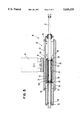
- FIG. 5 shows in an enlarged scale the detail "D" of FIG. 3 illustrating the equipment-holder bar according to the invention.
- the reference number 10 in the attached figures denotes generally an equipment-holder bar according to the invention.
- the equipment-holder bar 10 is installed in association with a rolling mill stand 11 for the purpose of positioning and thereafter clamping in position the equipment, such as a guide box 12 for the rolled stock, for instance, in relation to a rolling pass defined by rolling rolls 47.
- This equipment-holder bar 10 comprises a stationary body 13, which extends crosswise to the rolling mill stand 11 and is secured solidly, in this case, by fixture bolts 14, to a frame 15 of the rolling mill stand 11.
- This stationary body 13 includes on its outer surface a plurality of guides 16, which are positioned on different planes and with which there cooperate mating guides 17 included in a coordinated position on a slider 18.
- the equipment-holder bar 10 incorporates also means 46 to cool the rolling rolls 47, these means being positioned between the slider 18 and the relative roll 47 and being solidly fixed to the slider 18.
- the means 46 to cool the rolling rolls 47 are thus protected so that they cannot be damaged in the event of accidents or jamming of the rolled stock.
- the stationary body 13 and slider 18 include lower guides 16a-17a, downstream inclined guides 16b-17b and also upper movable guides 38.
- These guides 16 have the task of guiding and supporting the slider 18 in the traversing movement of the slider 18 crosswise to the rolling mill stand 11.
- the slider 18 can slide lengthwise in both directions along the stationary body 13 so as to position transversely the equipment, consisting in this case of the guide box 12, in relation to the rolling pass of the rolling mill stand 11.
- the slider 18 is positioned lengthwise by positioner means 37 which include an outer sleeve 21 associated with a rotary positioner shaft 31.
- the slider 18 is installed by means of a spline 20 on the outer sleeve 21, which cannot be rotated but can run lengthwise in a seating 22 defined by the stationary body 13 and by the slider 18.
- This outer sleeve 21 comprises a female-threaded portion 23 extending along its whole length and cooperates at its two ends with annular stoppers 24 fitted with a seal engagement to an inner sleeve 25; in this case the seal engagement of the annular stoppers 24 on the inner sleeve 25 is obtained with packings 30.
- the inner sleeve 25 includes in a substantially central position a bush 26 comprising a female-threaded portion 27 and a male-threaded portion 28.
- the inner sleeve 25 includes at its ends two annular stoppers 29 installed with a seal engagement obtained with packings 30 on the rotary positioner shaft 31, which is driven by a motor that is not shown here.
- the male-threaded portion 28 of the bush 26 cooperates with the female-threaded portion 23 of the outer sleeve 21, whereas the female-threaded portion 27 of the bush 26 cooperates with the intermediate threaded segment 32 of the rotary positioner shaft 31; this intermediate threaded segment 32 is delimited at both its ends by abutments 33.
- the inner sleeve 25 has been embodied with two segments, which are connected solidly at one side and the other to the bush 26.
- a part 45 of the stationary body 13 extending upstream of the lodgement seat 22 includes an inclined surface 39 cooperating with the upper movable guides 38.
- the slider 18 includes a movable body 40 associated with fork means 19 and with the positioner means 37; this movable body 40 has an inclined surface 41 cooperating with the upper movable guides 38, which are actuated perpendicularly by clamping/unclamping means 34 comprising a hydraulic actuator 35 so as to displace reciprocally and to clamp the stationary body 13 and the slider 18.
- the movable body 40 is conformed advantageously substantially as a cylinder and can be rotated circumferentially and be moved axially in a seating 44 included in the slider 18.
- the clamping in position of the slider 18 and therefore of the guide box 12 for the rolled stock is achieved by actuating the clamping/unclamping means 34 comprising the hydraulic actuator 35.
- the hydraulic actuator 35 acts on the fork means 19 associated with the stationary body 13 and cooperating with the slider 18.
- the actuation of the hydraulic actuator 35 causes the slider 18 to act with a desired pressure on the guides 16 of the frame 15 and thus clamps the slider 18 in position.
- the fork means 19 associated with the hydraulic actuator 35 cooperate on one side with an inclined surface 42 included on the slider 18 and on the other side with an inclined surface 43 on the guide box 12 for the rolled stock.
Landscapes
- Engineering & Computer Science (AREA)
- Mechanical Engineering (AREA)
- Metal Rolling (AREA)
- Refuge Islands, Traffic Blockers, Or Guard Fence (AREA)
- Laminated Bodies (AREA)
- Moulding By Coating Moulds (AREA)
- Lining Or Joining Of Plastics Or The Like (AREA)
- Reduction Rolling/Reduction Stand/Operation Of Reduction Machine (AREA)
- Grinding Of Cylindrical And Plane Surfaces (AREA)
Applications Claiming Priority (2)
| Application Number | Priority Date | Filing Date | Title |
|---|---|---|---|
| IT94UD000050A IT1266715B1 (it) | 1994-03-31 | 1994-03-31 | Barra porta attrezzature per gabbia di laminazione |
| ITUD94A0050 | 1994-03-31 |
Publications (1)
| Publication Number | Publication Date |
|---|---|
| US5630335A true US5630335A (en) | 1997-05-20 |
Family
ID=11421552
Family Applications (1)
| Application Number | Title | Priority Date | Filing Date |
|---|---|---|---|
| US08/411,462 Expired - Lifetime US5630335A (en) | 1994-03-31 | 1995-03-28 | Equipment-holder bar for a rolling mill stand |
Country Status (8)
| Country | Link |
|---|---|
| US (1) | US5630335A (de) |
| EP (1) | EP0674953B1 (de) |
| KR (1) | KR950031383A (de) |
| CN (1) | CN1062787C (de) |
| AT (1) | ATE165753T1 (de) |
| DE (1) | DE69502329T2 (de) |
| ES (1) | ES2117314T3 (de) |
| IT (1) | IT1266715B1 (de) |
Cited By (1)
| Publication number | Priority date | Publication date | Assignee | Title |
|---|---|---|---|---|
| US5970772A (en) * | 1999-03-01 | 1999-10-26 | Kotobuki Sangyo Kabushiki Kaisha | Positioning control device for guide apparatus |
Families Citing this family (2)
| Publication number | Priority date | Publication date | Assignee | Title |
|---|---|---|---|---|
| DE102006049161A1 (de) | 2006-10-18 | 2008-04-24 | Sms Demag Ag | Walzgerüst mit Stütz- und/oder Arbeitswalzen zum Walzen von Blechen oder Bändern |
| US20140373590A1 (en) * | 2013-06-25 | 2014-12-25 | Siemens Industry, Inc. | Worm and rack rest bar assembly |
Citations (6)
| Publication number | Priority date | Publication date | Assignee | Title |
|---|---|---|---|---|
| DE2129337A1 (de) * | 1971-06-12 | 1973-03-08 | Otto Doepper | Walzarmatur an der ein- oder auslaufseite von walzgeruesten |
| GB1351725A (en) * | 1971-03-06 | 1974-05-01 | Hille Eng Co Ltd | Rolling mill apparatus |
| JPS62292214A (ja) * | 1986-06-11 | 1987-12-18 | Kawasaki Steel Corp | 棒鋼圧延機のガイド移動装置 |
| JPH03216205A (ja) * | 1990-01-19 | 1991-09-24 | Kawasaki Steel Corp | 傾斜ロール圧延機におけるディスクガイドシューの研掃方法及び装置 |
| JPH03291103A (ja) * | 1990-04-05 | 1991-12-20 | Kawasaki Steel Corp | サイドガイド付竪ロール圧延機 |
| US5174142A (en) * | 1991-08-16 | 1992-12-29 | Pong David T | Method and apparatus for guiding a rod to a slitter station |
Family Cites Families (1)
| Publication number | Priority date | Publication date | Assignee | Title |
|---|---|---|---|---|
| GB135725A (en) * | 1919-02-26 | 1919-12-04 | Frederick Price | Inserted Blade Tools. |
-
1994
- 1994-03-31 IT IT94UD000050A patent/IT1266715B1/it active IP Right Grant
-
1995
- 1995-03-08 AT AT95103309T patent/ATE165753T1/de not_active IP Right Cessation
- 1995-03-08 ES ES95103309T patent/ES2117314T3/es not_active Expired - Lifetime
- 1995-03-08 EP EP95103309A patent/EP0674953B1/de not_active Expired - Lifetime
- 1995-03-08 DE DE69502329T patent/DE69502329T2/de not_active Expired - Fee Related
- 1995-03-28 US US08/411,462 patent/US5630335A/en not_active Expired - Lifetime
- 1995-03-30 KR KR1019950006957A patent/KR950031383A/ko not_active Application Discontinuation
- 1995-03-31 CN CN95103801A patent/CN1062787C/zh not_active Expired - Fee Related
Patent Citations (6)
| Publication number | Priority date | Publication date | Assignee | Title |
|---|---|---|---|---|
| GB1351725A (en) * | 1971-03-06 | 1974-05-01 | Hille Eng Co Ltd | Rolling mill apparatus |
| DE2129337A1 (de) * | 1971-06-12 | 1973-03-08 | Otto Doepper | Walzarmatur an der ein- oder auslaufseite von walzgeruesten |
| JPS62292214A (ja) * | 1986-06-11 | 1987-12-18 | Kawasaki Steel Corp | 棒鋼圧延機のガイド移動装置 |
| JPH03216205A (ja) * | 1990-01-19 | 1991-09-24 | Kawasaki Steel Corp | 傾斜ロール圧延機におけるディスクガイドシューの研掃方法及び装置 |
| JPH03291103A (ja) * | 1990-04-05 | 1991-12-20 | Kawasaki Steel Corp | サイドガイド付竪ロール圧延機 |
| US5174142A (en) * | 1991-08-16 | 1992-12-29 | Pong David T | Method and apparatus for guiding a rod to a slitter station |
Non-Patent Citations (6)
| Title |
|---|
| Patent Abstracts of Japan vol. 12, No. 182 (M 702) May 27, 1988 & JP A 62 292 214, Kawasaki Steel Dec. 18, 1987 Abstract. * |
| Patent Abstracts of Japan vol. 12, No. 182 (M-702) May 27, 1988 & JP-A-62 292 214, Kawasaki Steel Dec. 18, 1987 - Abstract. |
| Patent Abstracts of Japan vol. 15, No. 493 (M 1191) Dec. 13, 1991 & JP A 03 216 205 (Kawasaki Steel) Sep. 24, 1991 Abstract. * |
| Patent Abstracts of Japan vol. 15, No. 493 (M-1191) Dec. 13, 1991 & JP-A-03 216 205 (Kawasaki Steel) Sep. 24, 1991 - Abstract. |
| Patent Abstracts of Japan, vol. 16 No. 129 (M 1228) Apr. 2, 1992 & JP A 03 291 103 (Kawasaki Steel Dec. 20, 1991 Abstract. * |
| Patent Abstracts of Japan, vol. 16 No. 129 (M-1228) Apr. 2, 1992 & JP A-03 291 103 (Kawasaki Steel - Dec. 20, 1991- Abstract. |
Cited By (1)
| Publication number | Priority date | Publication date | Assignee | Title |
|---|---|---|---|---|
| US5970772A (en) * | 1999-03-01 | 1999-10-26 | Kotobuki Sangyo Kabushiki Kaisha | Positioning control device for guide apparatus |
Also Published As
| Publication number | Publication date |
|---|---|
| ITUD940050A1 (it) | 1995-10-01 |
| ATE165753T1 (de) | 1998-05-15 |
| EP0674953A1 (de) | 1995-10-04 |
| ES2117314T3 (es) | 1998-08-01 |
| DE69502329T2 (de) | 1998-09-03 |
| DE69502329D1 (de) | 1998-06-10 |
| CN1113459A (zh) | 1995-12-20 |
| ITUD940050A0 (it) | 1994-03-31 |
| IT1266715B1 (it) | 1997-01-14 |
| KR950031383A (ko) | 1995-12-18 |
| CN1062787C (zh) | 2001-03-07 |
| EP0674953B1 (de) | 1998-05-06 |
Similar Documents
| Publication | Publication Date | Title |
|---|---|---|
| DE19711317C2 (de) | Werkzeugmaschine | |
| US4589179A (en) | Flexible positioner | |
| US4743002A (en) | Automatic die clamp | |
| GB2100475A (en) | Apparatus to control the position of rolled strip during rolling | |
| US5630335A (en) | Equipment-holder bar for a rolling mill stand | |
| US10675721B2 (en) | Adjustable templates for pipe cutting frames | |
| WO2002092277A2 (de) | Motorspindel mit verbesserter bearbeitungsgenauigkeit sowie verfahren zum betrieb einer derartigen motorspindel | |
| EP1554079B1 (de) | Spannvorrichtung für längliche werkstücke in einer laserstrahlmaschine | |
| US20160333928A1 (en) | Machine tool with an improved covering for the translational movement guide | |
| DE102009011221B4 (de) | Spannvorrichtung für Hohlschaftwerkzeuge, insbesondere zum Einbau in eine Revolverscheibe | |
| EP0249021A2 (de) | Zentrier- und Spannsystem | |
| US4893532A (en) | Break away tool element and method of mounting | |
| CA2053405C (en) | Motion control system | |
| US4248074A (en) | Axial roll adjustment for a rolling mill | |
| EP0222732B1 (de) | Strangführung | |
| US20110109024A1 (en) | Apparatus for insertion and extraction of fuel injection lances into and out of the tuyere stock of a furnace blast | |
| CN2191048Y (zh) | 一种轧辊轴向固定装置 | |
| EP1105721B1 (de) | Walzstrasse | |
| DE102009025133B3 (de) | Vorrichtung zum Separieren von Bandstreifen eines längsgeteilten Bandes, insbesondere eines Metallbandes | |
| DE19514390A1 (de) | Schleifmaschine | |
| EP0509136B1 (de) | Walze und Walzgerüst | |
| KR200267433Y1 (ko) | 열간압연소재안내장치 | |
| DE19708686A1 (de) | Rohrtrenngerät | |
| DE8316776U1 (de) | Tisch einer Werkzeugmaschine | |
| EP2837463A1 (de) | Werkzeugmaschine mit einer Primärspule zur kontaktlosen Energie- und/oder Signalübertragung |
Legal Events
| Date | Code | Title | Description |
|---|---|---|---|
| AS | Assignment |
Owner name: DANIELI & C. OFFICINE MECCANICHE SPA, ITALY Free format text: ASSIGNMENT OF ASSIGNORS INTEREST;ASSIGNORS:TINGVALL, LARS GUNNAR;MIKAEL, LENNART;NONINO, GIANNI;AND OTHERS;REEL/FRAME:007480/0851 Effective date: 19950228 |
|
| STCF | Information on status: patent grant |
Free format text: PATENTED CASE |
|
| FPAY | Fee payment |
Year of fee payment: 4 |
|
| FEPP | Fee payment procedure |
Free format text: PAYOR NUMBER ASSIGNED (ORIGINAL EVENT CODE: ASPN); ENTITY STATUS OF PATENT OWNER: LARGE ENTITY |
|
| FPAY | Fee payment |
Year of fee payment: 8 |
|
| FPAY | Fee payment |
Year of fee payment: 12 |