US5625559A - Transport management control apparatus and method for unmanned vehicle system - Google Patents
Transport management control apparatus and method for unmanned vehicle system Download PDFInfo
- Publication number
- US5625559A US5625559A US08/493,783 US49378395A US5625559A US 5625559 A US5625559 A US 5625559A US 49378395 A US49378395 A US 49378395A US 5625559 A US5625559 A US 5625559A
- Authority
- US
- United States
- Prior art keywords
- route
- travel
- unmanned
- node
- unmanned vehicle
- Prior art date
- Legal status (The legal status is an assumption and is not a legal conclusion. Google has not performed a legal analysis and makes no representation as to the accuracy of the status listed.)
- Expired - Fee Related
Links
- 238000000034 method Methods 0.000 title claims abstract description 134
- 238000004088 simulation Methods 0.000 claims abstract description 11
- 238000012545 processing Methods 0.000 claims description 18
- 238000004364 calculation method Methods 0.000 claims description 17
- 230000002123 temporal effect Effects 0.000 claims 2
- YTAHJIFKAKIKAV-XNMGPUDCSA-N [(1R)-3-morpholin-4-yl-1-phenylpropyl] N-[(3S)-2-oxo-5-phenyl-1,3-dihydro-1,4-benzodiazepin-3-yl]carbamate Chemical compound O=C1[C@H](N=C(C2=C(N1)C=CC=C2)C1=CC=CC=C1)NC(O[C@H](CCN1CCOCC1)C1=CC=CC=C1)=O YTAHJIFKAKIKAV-XNMGPUDCSA-N 0.000 claims 1
- 238000007726 management method Methods 0.000 abstract description 28
- 230000007704 transition Effects 0.000 description 68
- 238000010586 diagram Methods 0.000 description 41
- 230000002860 competitive effect Effects 0.000 description 13
- 238000010276 construction Methods 0.000 description 3
- 230000000694 effects Effects 0.000 description 3
- 238000011156 evaluation Methods 0.000 description 3
- 230000000414 obstructive effect Effects 0.000 description 3
- 230000001276 controlling effect Effects 0.000 description 2
- 238000007796 conventional method Methods 0.000 description 2
- 238000006073 displacement reaction Methods 0.000 description 2
- 238000011835 investigation Methods 0.000 description 2
- 239000000203 mixture Substances 0.000 description 2
- 230000003068 static effect Effects 0.000 description 2
- 102100022441 Sperm surface protein Sp17 Human genes 0.000 description 1
- 230000015572 biosynthetic process Effects 0.000 description 1
- 239000000969 carrier Substances 0.000 description 1
- 230000006870 function Effects 0.000 description 1
- 239000003550 marker Substances 0.000 description 1
- 230000001105 regulatory effect Effects 0.000 description 1
- 239000007787 solid Substances 0.000 description 1
- 238000012360 testing method Methods 0.000 description 1
- 238000013519 translation Methods 0.000 description 1
- 230000014616 translation Effects 0.000 description 1
- 238000002604 ultrasonography Methods 0.000 description 1
Images


Classifications
-
- G—PHYSICS
- G05—CONTROLLING; REGULATING
- G05D—SYSTEMS FOR CONTROLLING OR REGULATING NON-ELECTRIC VARIABLES
- G05D1/00—Control of position, course, altitude or attitude of land, water, air or space vehicles, e.g. using automatic pilots
- G05D1/02—Control of position or course in two dimensions
- G05D1/021—Control of position or course in two dimensions specially adapted to land vehicles
- G05D1/0268—Control of position or course in two dimensions specially adapted to land vehicles using internal positioning means
- G05D1/0274—Control of position or course in two dimensions specially adapted to land vehicles using internal positioning means using mapping information stored in a memory device
-
- G—PHYSICS
- G05—CONTROLLING; REGULATING
- G05B—CONTROL OR REGULATING SYSTEMS IN GENERAL; FUNCTIONAL ELEMENTS OF SUCH SYSTEMS; MONITORING OR TESTING ARRANGEMENTS FOR SUCH SYSTEMS OR ELEMENTS
- G05B19/00—Programme-control systems
- G05B19/02—Programme-control systems electric
- G05B19/418—Total factory control, i.e. centrally controlling a plurality of machines, e.g. direct or distributed numerical control [DNC], flexible manufacturing systems [FMS], integrated manufacturing systems [IMS] or computer integrated manufacturing [CIM]
- G05B19/4189—Total factory control, i.e. centrally controlling a plurality of machines, e.g. direct or distributed numerical control [DNC], flexible manufacturing systems [FMS], integrated manufacturing systems [IMS] or computer integrated manufacturing [CIM] characterised by the transport system
- G05B19/41895—Total factory control, i.e. centrally controlling a plurality of machines, e.g. direct or distributed numerical control [DNC], flexible manufacturing systems [FMS], integrated manufacturing systems [IMS] or computer integrated manufacturing [CIM] characterised by the transport system using automatic guided vehicles [AGV]
-
- G—PHYSICS
- G05—CONTROLLING; REGULATING
- G05D—SYSTEMS FOR CONTROLLING OR REGULATING NON-ELECTRIC VARIABLES
- G05D1/00—Control of position, course, altitude or attitude of land, water, air or space vehicles, e.g. using automatic pilots
- G05D1/02—Control of position or course in two dimensions
- G05D1/021—Control of position or course in two dimensions specially adapted to land vehicles
- G05D1/0255—Control of position or course in two dimensions specially adapted to land vehicles using acoustic signals, e.g. ultra-sonic singals
-
- G—PHYSICS
- G05—CONTROLLING; REGULATING
- G05D—SYSTEMS FOR CONTROLLING OR REGULATING NON-ELECTRIC VARIABLES
- G05D1/00—Control of position, course, altitude or attitude of land, water, air or space vehicles, e.g. using automatic pilots
- G05D1/02—Control of position or course in two dimensions
- G05D1/021—Control of position or course in two dimensions specially adapted to land vehicles
- G05D1/0287—Control of position or course in two dimensions specially adapted to land vehicles involving a plurality of land vehicles, e.g. fleet or convoy travelling
- G05D1/0289—Control of position or course in two dimensions specially adapted to land vehicles involving a plurality of land vehicles, e.g. fleet or convoy travelling with means for avoiding collisions between vehicles
-
- G—PHYSICS
- G05—CONTROLLING; REGULATING
- G05D—SYSTEMS FOR CONTROLLING OR REGULATING NON-ELECTRIC VARIABLES
- G05D1/00—Control of position, course, altitude or attitude of land, water, air or space vehicles, e.g. using automatic pilots
- G05D1/02—Control of position or course in two dimensions
- G05D1/021—Control of position or course in two dimensions specially adapted to land vehicles
- G05D1/0287—Control of position or course in two dimensions specially adapted to land vehicles involving a plurality of land vehicles, e.g. fleet or convoy travelling
- G05D1/0291—Fleet control
-
- G—PHYSICS
- G05—CONTROLLING; REGULATING
- G05B—CONTROL OR REGULATING SYSTEMS IN GENERAL; FUNCTIONAL ELEMENTS OF SUCH SYSTEMS; MONITORING OR TESTING ARRANGEMENTS FOR SUCH SYSTEMS OR ELEMENTS
- G05B2219/00—Program-control systems
- G05B2219/30—Nc systems
- G05B2219/31—From computer integrated manufacturing till monitoring
- G05B2219/31003—Supervise route, reserve route and allocate route to vehicle, avoid collision
-
- G—PHYSICS
- G05—CONTROLLING; REGULATING
- G05B—CONTROL OR REGULATING SYSTEMS IN GENERAL; FUNCTIONAL ELEMENTS OF SUCH SYSTEMS; MONITORING OR TESTING ARRANGEMENTS FOR SUCH SYSTEMS OR ELEMENTS
- G05B2219/00—Program-control systems
- G05B2219/30—Nc systems
- G05B2219/32—Operator till task planning
- G05B2219/32372—Petrinet, coloured, inhibitor arc, timed, object token Petrinet
-
- Y—GENERAL TAGGING OF NEW TECHNOLOGICAL DEVELOPMENTS; GENERAL TAGGING OF CROSS-SECTIONAL TECHNOLOGIES SPANNING OVER SEVERAL SECTIONS OF THE IPC; TECHNICAL SUBJECTS COVERED BY FORMER USPC CROSS-REFERENCE ART COLLECTIONS [XRACs] AND DIGESTS
- Y02—TECHNOLOGIES OR APPLICATIONS FOR MITIGATION OR ADAPTATION AGAINST CLIMATE CHANGE
- Y02P—CLIMATE CHANGE MITIGATION TECHNOLOGIES IN THE PRODUCTION OR PROCESSING OF GOODS
- Y02P90/00—Enabling technologies with a potential contribution to greenhouse gas [GHG] emissions mitigation
- Y02P90/02—Total factory control, e.g. smart factories, flexible manufacturing systems [FMS] or integrated manufacturing systems [IMS]
-
- Y—GENERAL TAGGING OF NEW TECHNOLOGICAL DEVELOPMENTS; GENERAL TAGGING OF CROSS-SECTIONAL TECHNOLOGIES SPANNING OVER SEVERAL SECTIONS OF THE IPC; TECHNICAL SUBJECTS COVERED BY FORMER USPC CROSS-REFERENCE ART COLLECTIONS [XRACs] AND DIGESTS
- Y02—TECHNOLOGIES OR APPLICATIONS FOR MITIGATION OR ADAPTATION AGAINST CLIMATE CHANGE
- Y02P—CLIMATE CHANGE MITIGATION TECHNOLOGIES IN THE PRODUCTION OR PROCESSING OF GOODS
- Y02P90/00—Enabling technologies with a potential contribution to greenhouse gas [GHG] emissions mitigation
- Y02P90/60—Electric or hybrid propulsion means for production processes
Definitions
- the present invention relates to a transport management control apparatus and method for the same which in a unmanned carrier system such as that found in factories and the like, maintains the transport of unmanned carrier vehicles, and also determines the carrier route.
- FIG. 1 shows a constructional outline of an automated carrier system possessing a plurality of unmanned vehicles.
- a transport management control apparatus 100 for conducting management of an unmanned carrier system, a passage type travel grid 101, and unmanned vehicles #1 to #5 are provided.
- a plurality of nodes 1, 2 . . . 28 exist, at which unmanned vehicles #1 to #5 stop, change directions, and unload their contents.
- each of unmanned vehicles #1 to #5 possesses a function for determining its travel route up until its individual target point (hereafter referred to as "target node"); these unmanned vehicles move over their individually-determined routes to their target nodes which are determined by means of transport management control apparatus 100.
- target node a function for determining its travel route up until its individual target point
- move designations are sent from transport management control apparatus 100 to unmanned vehicles #1 to #5 as shown in FIG. 1.
- These unmanned vehicles #1 to #5 then follow the optimal travel routes to respective target destinations.
- the costs of each of the travel intervals (arcs) linking neighboring nodes are used, and the route which provides the minimum total cost value is selected.
- the travel routes of other unmanned vehicles are not taken into consideration; in other words, the optimal travel route of one unmanned vehicle is determined without considering the existence of other unmanned vehicles.
- the aforementioned costs represent characteristics such as the time required for transit of each arc, and the like.
- FIG. 2 shows the cost involved in travel grid 101; in this figure, the cost for each arc is shown in ().
- FIGS. 3 and 4 show the travel route of each unmanned vehicle #1 to #5 formed at this time;
- FIG. 3 is a transport diagram showing the travel routes of each of unmanned vehicles #1 to #5 using a solid line, dotted line, short-dashed line, single-dotted chain line, and double-dotted chain line, respectively;
- FIG. 4 shows the aforementioned routes in node series.
- unmanned vehicles #1 to #5 each independently send to transport management control apparatus 100 the node numbers on their respective traveling routes, in movement order, and the reservation of the nodes is then carried out.
- Transport management control apparatus 100 then examines in order the node series requested in the aforementioned (FIG. 4), and allows reservations from other unmanned vehicles in the case when nodes are not previously reserved.
- Unmanned vehicles #1 to #5 then move up to the allowable nodes. By means of this aforementioned control, collisions between the unmanned vehicles are avoided.
- FIG. 5 is a transport diagram showing the present positions and subsequent travel routes of each unmanned vehicle #1 to #5 at this time.
- a competition for travel routes is generated in which unmanned vehicles #1 and #2 move in opposite directions on the same travel route.
- one of these unmanned vehicles changes routes neither will be able to reach the desired target.
- neither of unmanned vehicles #1 and #2 will be allowed to reserve the node of their subsequent destination.
- unmanned vehicle #1 finds a detour route (node 4 ⁇ 18 ⁇ 19 ⁇ 20 ⁇ 12 ⁇ . . . ) and reserves node 18 and then moves to the reserved node. In this manner, it is then possible for unmanned vehicles #2 to move along its original route; however, another competition for travel routes is then generated between unmanned vehicles #1 and #3.
- FIG. 6 is a transport diagram showing the routes of unmanned vehicles #1 to #5 at this time. Accordingly, unmanned vehicle #3 locates a detour route (node 20 ⁇ 6 ⁇ 5 ⁇ 4 ⁇ 3 ⁇ 16 ⁇ 15), and then reserves and moves to node 6.
- the applicant of the present invention has previously proposed the method employing the structure shown in FIG. 7 (Japanese Patent Application No. Hei 3-14133) as an optimal route determining apparatus, in which at least the data establishment is complete, in unmanned carrier systems.
- FIG. 7 shows the composition of an unmanned carrier vehicle
- reference 16 indicates a map data memory which stores map data of the travel grid, and data relating to the nodes on the travel grid at which the unmanned carrier vehicle can stop, the coordinates thereof, or connection relationships are stored therein.
- reference numeral 17 indicates an unmanned vehicle data memory which stores data relating to the speed and the like of the unmanned carrier vehicles.
- reference numeral 18 indicates a graph generator, which creates the graph GO shown below.
- Reference 19 indicates an optimal route generator; it determines the departure node and target node from the carrying directive supplied to the unmanned carrier vehicles from a control unit, which is not depicted in the Figure. Next, this generator generates an optimal route which minimizes estimated costs based on the graph GO determined in the graph generator 18 and on the unmanned carrier vehicle data and map data.
- d ij represents the straight line distance (mm) between the initial point node i and the final point node j, and is expressed by:
- x i and y i indicate the x and y coordinates (mm) of node 1
- x j and y j indicate the x and y coordinates (mm) of node j.
- the cost B ij of the arc from node i to node j is determined by means of the formula (4) below.
- the distance d ij is determined as shown above, while v ij represents the movement speed (m/sec) from node i to node j, so that B ij has an amount in correspondence with the movement time between the nodes.
- the cost B ij of the are from node i to node j is determined in accordance with the formula (5) as shown below.
- P ij is a penalty coefficient expressing the "desirability" in accordance with the directionality of the route. For example, if the direction from node i to node j is an "undesirable" direction (opposite direction), then P ij is a negative number and the costs are raised, while when this direction is a "desirable" direction (normal direction) then P ij has a positive value, and it is possible to reduce the costs.
- the absolute value of the coefficient P ij is set within a range of "0-1" in accordance with the degree of desirability.
- the shortest route having the smallest estimated costs (hereinbelow referred to as the shortest route) in the case in which 2 freely selected points (the departure point and the target point) are connected.
- travel grids have considerable regularity, such as the ladder shape shown in FIG. 8, or the square lattice shown in FIG. 9.
- the lattice shaped travel grid shown in FIG. 8 is constructed from the node labeled "28".
- FIG. 10 shows the (x,y) coordinate data for each node.
- FIG. 11 represents a compilation of the node numbers of the initial point and the final point, the direction, and the velocity data with respect to all scenes which are capable of adjoining movement in this lattice shaped travel grid.
- the directionality of the route is not considered and all directional data have a value of "0".
- the movement velocity differs in the horizontal direction and the vertical direction, so that costs are calculated by means of formula (4), which takes account of movement velocity.
- FIG. 12 shows the results of the calculation at the side of each arc.
- the costs of arcs in which the initial point and the final point are opposite is equal, so that for example, the costs of the arcs leading to nodes 1 and 2 are calculated by means of the following formula: ##EQU1## and are thus calculated to be "3000".
- the reason why the velocity was divided by "1000" was in order to bring it in line with the units of formula (4).
- An identical calculation is performed with respect to the other arcs.
- the costs should be estimated for each arc along which travel is conducted and the route having the smallest total cost should be selected. However, here, as shown in FIG. 13, there are 8 shortest routes having equal total costs.
- FIG. 9 shows the ladder shaped travel grid shown in FIG. 9 from the node numbered "100".
- FIG. 14 shows the (x, y) coordinate data for each node.
- the movement velocity between the nodes is set to (1000 mm/sec) in all cases, and the scene data are omitted. Furthermore, the distance between adjoining nodes is set to 1 meter in all cases, so that the costs for each arc as calculated by means of formulas (2) or (4) have an identical value of (1000) in all cases.
- the number of shortest routes from the node at the lower left to the node at the upper right is determined by the following formula:
- a transport management control apparatus which controls the transport of a plurality of unmanned vehicles traveling along a travel route comprising a plurality of nodes constituting stopping positions, and connecting routes connecting these nodes.
- the transport management control apparatus comprises:
- route search means which searches, for each unmanned vehicle, an optimal travel route which connects a present node of the unmanned vehicle to a target node of the unmanned vehicle and has a minimum cost
- route arrangement means which, based on the searched result by the route search means, controls the route search means so that a travel interval having a specified moving direction is not searched as a part of optimal travel routes, and causes the route search means to search the optimal routes in order to obtain the final optimal travel routes which have no conflict.
- a transport management control apparatus which has first means for simulating the movements of the unmanned vehicles by using a simulation model and for detecting whether the unmanned vehicles meet a deadlock problem, based on the simulation result, and second means for resolving the deadlock problem.
- a transport management control method for controlling the transport of a plurality of unmanned vehicles traveling along a travel route comprising a plurality of nodes comprising stopping positions and connecting routes connecting these nodes.
- the transport management control method has the steps of:
- a first step in which the optimal travel route of each of a plurality of unmanned carrier vehicles is determined
- a third step in which processing is halted in the case in which opposite direction intervals are not present, and in other cases, costs of the opposite direction intervals are estimated;
- a fourth step in which a direction is applied to the opposite direction interval having the highest cost so that this interval has one direction;
- a fifth step in which, in the traveling routes to which a direction has been applied, the optimal traveling routes of all unmanned carrier vehicles are again determined;
- a transport management control method for controlling the transport of a plurality of unmanned vehicles traveling over a travel route formed from a plurality of node provided at stationary positions, and connecting routes connecting the intervals between said nodes.
- the transport management apparatus has the steps of:
- step d adding a detour route to the route of an unmanned vehicle in the case when the deadlock problem cannot be solved by means of said step d;
- step e adding a passing route to the route of an unmanned vehicle in the case when the deadlock problem cannot be solved by means of said step e.
- the apparatus comprises:
- first cost calculation means in which, with respect to a set of travel intervals connecting a first and second node which Join one another and between which travel is possible, among a plurality of nodes on a travel route, calculates a first cost for each travel interval, based on the distance between the nodes and the movement time;
- second cost calculation means which, when the target nodes are directed, calculates the angular difference between the direction of the first node, as seen from the target node, and a prespecified direction, and calculates the angular difference between the direction of the second node, as seen from the target node, and a prespecified direction, and based on these angular differences, calculates a second cost for each travel interval;
- addition means for adding the results of the cost calculation of the first and second cost calculation means for each travel interval
- route generation means which, based on the added costs calculated by means of the addition means, selects the case in which the estimated value of the added costs of each travel interval has the smallest value as the optimal route from the departure node to the target node.
- FIG. 1 shows a construction of a conventional unmanned carrier system.
- FIG. 2 shows the costs on a travel grid 101 of the conventional example shown in FIG. 1.
- FIGS. 3 and 4 show movement routes in a first conventional example.
- FIG. 5 shows movement routes in a second conventional example.
- FIG. 6 shows movement routes in a third conventional example.
- FIG. 7 shows a construction of a conventional optimal route determining apparatus.
- FIG. 8 shows travel grid having ladder shape.
- FIG. 9 shows travel grid having square lattice shape.
- FIG. 10 shows the (x, y) coordinate data for each node in the travel grid shown in FIG. 8.
- FIG. 11 shows compilation of the node numbers of the initial point and the final point, the direction, and the velocity data with respect to all scenes in the travel grid shown in FIG. 8.
- FIG. 12 shows the calculated results of the costs of the arcs in the grid shown in FIG. 8.
- FIG. 13 shows the shortest routes, each one requiring the minimum cost ,in the grid shown in FIG. 8.
- FIG. 14 shows the (x, y) coordinate data for each node in the travel grid shown in FIG. 9.
- FIG. 15 is a block diagram showing a transport management control apparatus according to an embodiment of the present invention.
- FIG. 16 shows a "tree" diagram used in route planning.
- FIG. 17 is a flow chart showing the route planning process of route planning portion 109.
- FIGS. 18 to 23 are transport diagrams showing a first example of the operation involved in an operational planning process.
- FIG. 24 shows oposite direction intervals in travel routes and the results of the ectimates of the costs.
- FIGS. 25 to 27 are transport diagrams showing a second example of the operation.
- FIG. 28 shows a portion of the tree diagram showing the second example of the operation.
- FIG. 29 is a transport diagram for use in describing an operation using a Petri net.
- FIG. 30 shows departure nodes and target nodes of unmanned vehicle shown in FIG. 29.
- FIG. 31 is a Petri net diagram which models the transport diagram shown in FIG. 29.
- FIG. 32 is a flow chart showing a relief route search procedure of operational planning portion 108.
- FIG. 33 is a transport diagram of an example of the operations of the relief route search procedure.
- FIG. 34 is a flow chart showing a deadlock recognition procedure of operational planning portion 108.
- FIGS. 35 and 36 are transport diagrams showing an example of the operations in deadlock recognition procedure.
- FIG. 37 shows results of an examination conducted in the deadlock recognition procedure.
- FIG. 38 is a flow chart showing the ignition sequence adjusting procedure of operational planning portion 108.
- FIG. 39 is a transport diagram showing an example of the operations of an ignition sequence adjusting procedure.
- FIG. 40 shows a node reservation sequence
- FIG. 41 is a flow chart showing a detour route search procedure of operational planning portion 108.
- FIGS. 42 and 43 are transport diagrams showing an example of the operations of detour route search procedure.
- FIG. 44 is a flow chart showing a passing route search procedure of operational planning portion 108.
- FIGS. 45 and 46 are transport diagrams showing an operational example of the passing route search procedure.
- FIGS. 47 to 49 are flow charts showing an operational planning procedure (main procedure) of operational planning portion 108.
- FIGS. 50 to 56 are Petri net diagrams showing an operational example of operational planning portion 108.
- FIG. 57 is a node reservation sequence showing a result of the operational example.
- FIG. 58 is a transport planning diagram showing a result of the same operational example.
- FIG. 59 shows an initial designation of Operational Example 1 of transport management control apparatus 102.
- FIG. 60 shows a standard routing of the same.
- FIG. 61 shows a final routing of the same.
- FIG. 62 shows the initial routing of the same.
- FIG. 63 shows the standard routing of the same.
- FIG. 64 shows the final routing of the same.
- FIG. 65 is a transport planning diagram of this Operational Example 1.
- FIG. 66 show the standard routing of Operational Example 2 of transport management apparatus 102.
- FIG. 67 shows the final routing of Operational Example 2 of transport management control apparatus 102.
- FIGS. 68 to 70 are transport diagrams showing the initial routing, standard routing, and final routing, respectively, of the same Operational Example 2.
- FIG. 71 is a transport planning diagram of the same Operational Example 2.
- FIG. 72 is a block diagram showing an optimal route determining apparatus according to a preferred embodiment of the present invention.
- FIG. 73 shows angular potential costs used for the optimal route determining apparatus shown in FIG. 72.
- FIGS. 74 and 75 shows calculation results of the costs.
- FIG. 15 is a block diagram showing the construction of a transport management control apparatus 102 according the present embodiment.
- a transport control data memory 103 is provided for recording the movement routes of each unmanned vehicle as well as the node reservation sequence; a carrier designation table memory 104 for recording the position and carrier destinations of the items to be transported; an unmanned vehicle data memory 105 for recording states, such as the present position, movement direction, and the like of each unmanned vehicle; a travel grid data memory 106 for recording the coordinates of each node along the travel grid, as well as the connection relationships and costs therein (FIG. 2); and a controller 107 for determining the optimum travel route and operational sequence of the unmanned vehicles, are provided.
- the aforementioned controller 107 is formed by means of a CPU or the like, and can be functionally divided into operational planning portion 108, route planning portion 109, and route search portion 110.
- route search portion 110 When a route search directive is sent from route planning portion 109, then route search portion 110 first determines the route from the departure node to the target node. Next, the costs of each route are estimated from the costs which are stored in travel grid data memory 106, and the route having the smallest costs is selected as the optimal route.
- Travel grid data memory 106 stores the costs of each arc of travel grid 101 as shown in FIG. 2.
- the numbers within the parentheses show the costs of each arc; for example, the costs between nodes 1 and 2 is "3000".
- the estimated costs of the route along nodes 1 ⁇ 2 ⁇ 3 ⁇ 4 is the smallest, at "7500”. and this route is thus selected as the optimal route.
- the directional information discussed hereinbelow is contained in the route search directive, routes having a direction opposite to this applied direction are not selected.
- Route search portion 110 outputs the routes determined by means of the above method, and the costs thereof, to route planning portion 109.
- the routes created here are the optimal routes only in the case in which there is no conflict on the travel grid.
- the final travel grids are determined using a tree search method.
- the "tree" to be discussed herein has a structure such as that shown in FIG. 16, in which branching is conducted in a downward direction.
- references N1, N2, . . . indicate branching points at which branching conditions are introduced, and among these, branching point N1 is the root branching point at which branching is initiated.
- branching point N2 is taken to be the present branching point
- branching point N1 is the master branching point of branching point N2
- branching points N3 and N4 are subsidiary branching points of branching point N2.
- the search is fundamentally conducted from the upper branching points in the direction of the lower branching points; however, in cases in which the search becomes impossible, the master branching point is temporarily returned to (hereinbelow, this is termed "backtracking") and branching is conducted to other branching points.
- backtracking this is termed "backtracking"
- FIG. 17 is a flow chart showing the processing conducted by route planning portion 109; the explanation hereinbelow will be conducted on the basis of this Figure.
- step SP2 When processing is initiated (step SP1), in step SP2, a search directive is sent to route search portion 110, and the traveling routes of each unmanned carrier vehicle are determined.
- the route search portion 110 which has received a search directive, searches for the route by means of the method described above, and outputs the results to route planning portion 109.
- the target nodes of the unmanned carrier vehicles which are determined by means of the data which is stored in carrying directive table memory 103, are contained.
- step SP3 the root branching point of the tree is cleared.
- step SP4 a freely selected interval in which the movement of two unmanned carrier vehicles is conducted so as to be in opposite directions (opposite direction interval) is found, based on the traveling route of each unmanned carrier vehicle which is supplied from route search portion 110, and this is conducted for all combinations of unmanned carrier vehicles.
- step SP5 if no opposite direction intervals are present in the results of step SP4, processing is terminated (step SP16), and in the case in which opposite direction intervals are present, control proceeds to the following step SP6. Furthermore, in the ease in which opposite direction intervals are not present, the traveling routes at this time becomes the final traveling routes.
- step SP6 the costs of the opposite direction intervals of the routes of each unmanned carrier vehicle are estimated.
- the costs of the opposite direction intervals are read out from travel grid data memory 106.
- the cost per occurrence of conflict is estimated.
- step SP7 a conflicted unmanned carrier vehicle set is created in the order of increasing costs of the traveling routes and listed by number attached to the unmanned carrier vehicles.
- step SP8 a branching point having this conflicted unmanned carrier vehicle set is appended below the master branching point.
- the conflicted unmanned carrier vehicle set is established in the root branching point.
- an unmanned carrier vehicle to be observed is determined from the conflicted unmanned carrier vehicle set.
- This unmanned carrier vehicle to be observed is selected, in order, from the first unmanned carrier vehicle in the conflicted unmanned carrier vehicle set which is listed in order of increasing cost. Furthermore, in the case in which there is no succeeding unmanned carrier vehicle, a determination is made that there is no unmanned carrier vehicle to be observed.
- step SP10 in the case in which an unmanned carrier vehicle to be observed was not present in the processing of the previous step SP9, control proceeds to the following step SP11, while in the case in which an unmanned carrier vehicle to be observed was present, branching is conducted to step SP13.
- step SP11 an investigation is made into whether the present branching point is prior to the root branching or not, and in the case in which the present branching point is not the root branching point, control passes to the following step SP12, while in the case in which the present branching point is the root branching point, that is to say, in the case in which route management has failed in all of the conflicted unmanned carrier vehicle sets of the route branching point, all processing is terminated as a result of route management failure (step SP17).
- step SP12 the processing of the present branching point is passed to the master branching point (backtracking) and control returns to the processing of step SP9. Furthermore, the directional application which was conducted at the time of the branching to the present branching point is canceled at this point.
- step SP13 in the travel grid, opposite direction intervals on the route of the unmanned carrier vehicle to be observed have a direction which is opposite to the direction of movement of the unmanned carrier vehicle applied thereto (the route is made unidirectional), and this is added to the directional information.
- step SP14 a search directive is sent to route search unit 108, and all the routes of the unmanned carrier vehicles in the travel grid to which a direction has been applied are predetermined.
- step SP15 an investigation is made as to whether routes which were not determined in the route search of the previous step SP14 are present or not, and in the case in which such routes are present, control passes to the following step SP16, while in the case in which such routes are not present, control returns to step SP4.
- step SP16 the directional application of the travel grid which was conducted in step SP13 is canceled, and then control returns to step SP9.
- this interval is not included in the opposite direction interval.
- FIGS. 18 to 23 are transport diagrams showing the carrying route of each unmanned carrier vehicle; portions therein corresponding to portions in FIG. 3 have identical reference numbers, and an explanation thereof will omitted here.
- the departure nodes and target nodes of each unmanned carrier vehicle #1 through #5 are identical to those in FIG. 3.
- route planning portion 109 determines the target node of the movement of unmanned carrier vehicles #1 through #5, based on the carrying directives stored in carrying directive table memory 104, and a search directive is conducted with respect to route search portion 110.
- Route search portion 110 finds the respective traveling routes of unmanned carrier vehicles #1 through #5 in accordance with the search directive, and the results thereof are outputted to route planning portion 109 (FIG. 18).
- Route planning portion 109 finds the opposite direction interval, and the carriers involved in the conflict, from the traveling routes (initial routes) supplied from route search portion 110, and estimates the cost of the opposite direction intervals.
- FIG. 24 shows the opposite direction intervals and the results of the estimates of the costs thereof. Next, the results of the estimate are listed in order of increasing cost, and the conflicted unmanned carrier vehicle set shown below is created.
- Unmanned carrier vehicle composition (#2, #1, #5, #3, #4)
- route planning portion 109 establishes the conflicted unmanned carrier vehicle set in the root branching point N1 shown in FIG. 16, and the first unmanned carrier vehicle #2 is selected as the unmanned carrier vehicle to be observed.
- directional application in a direction opposite to the direction of movement of unmanned carrier vehicle #2 (making this interval unidirectional) is conducted with respect to the opposite direction interval of the route of unmanned carrier vehicle #2, and in the subsequent route search, the movement is limited to the direction nodes 2 ⁇ 3 ⁇ 4 ⁇ 5 ⁇ 6 ⁇ 7.
- route planning portion 109 outputs a search directive containing directional information, and route search portion 110 again conducts a route search based on the directional information.
- FIG. 19 is a transport diagram showing the results of this search, in the diagram, the interval to which direction has been applied is indicated by the thick arrows. Based on these results, route planning portion 109 again conducts an estimate of the costs of each route, and the set (#1. #3, #4, #5) is created.
- a branching point N2 is appended below the branching point N1 of the tree (FIG. 16), and the conflicted unmanned carrier vehicle set described above is established in branching point N2.
- the unmanned carrier vehicle #2 of branching point N1 is connected with branching point N2.
- the unmanned carrier vehicle #1 which stands at the head of the set of the branching point N2 is selected as the unmanned carrier vehicle to be observed, the directional application of the opposite direction intervals is conducted, and this is appended to the previous directional application.
- route search portion 110 the search results shown in FIG. 20 are obtained.
- nodes 9 ⁇ 8 and 13 ⁇ 12 are again made unidirectional.
- Route planning portion 109 again conducts a cost estimate, creates the conflicted unmanned carrier vehicle set (#5, #4, #2, and #3), and establishes this conflicted unmanned carrier vehicle set in branching point N3 below branching point N2 in the conflict tree.
- unmanned careier vehicle #5 becomes the unmanned carrier vehicle to be observed, and identical processing is conducted.
- a directional application nodes 24 ⁇ 23 ⁇ 22 ⁇ 21 ⁇ 20 ⁇ 19 ⁇ 18 ⁇ 17.gtoreq.16 ⁇ 15
- This state indicates a failure of route alignment (the x symbol in FIG. 16), and at this time, the directional application of the routes which was established is canceled.
- the unmanned carrier vehicle which is to be observed is changed to the following unmanned carrier vehicle #1 in the conflicted unmanned carrier vehicle set of branching point N3, and identical processing is conducted; however, here as well, a route could not be obtained for the unmanned carrier vehicle #1.
- the unmanned carrier vehicles are selected in order from the same conflicted unmanned carrier vehicle set as the unmanned carrier vehicle which is to be observed, and identical processing is conducted; however, all route alignments fall.
- unmanned carrier vehicle #1 is selected as the unmanned carrier vehicle to be observed, and directional application and a route search are conducted (FIG. 23). At this time, there is no opposite direction interval present in the route, so that the route alignment is successful (shown by the concentric circle mark in FIG. 16), and the routes at this point become the final traveling routes.
- the traveling routes are transmitted from transport management control apparatus 102 to unmanned carrier vehicles 1 through #5, and the unmanned carrier vehicles #1 through #5 conduct movement in accordance with these routes.
- This travel grid 110 represents the travel grid 101 (FIG. 3) described above, in which the interval between nodes 20 and 21 has been rendered impassable.
- the departure nodes and target nodes of each of the unmanned carrier vehicles #1 through #5 are identical, to those of the operational example 1 (FIG. 3).
- the intervals between nodes 6 and 7, nodes 7 and 8, and nodes 21 and 22 possess no detour routes other than the routes linking these nodes, so that they are not included in the opposite direction intervals.
- processing which is identical to operational example 1 is conducted, and first, initial routes such as those shown in FIG. 25 are determined. Based on these, the cost estimate is conducted, a conflicted unmanned carrier vehicle set (#1, #2, #4, #5, #3) is created, and this conflicted unmanned carrier vehicle set is established in the root branching point N6 of the tree shown in FIG. 28. Next, the unmanned carrier vehicle #1, which is at the lead end of this conflicted unmanned carrier vehicle set, is made the unmanned carrier vehicle to be observed, directional application (nodes 13 ⁇ 12 ⁇ 11 ⁇ 10 ⁇ 9 ⁇ 8, and nodes 6 ⁇ 5 ⁇ 4 ⁇ 3 ⁇ 2) is conducted, and after this, the traveling routes are predetermined.
- an unmanned carrier vehicle which travels in the opposite direction is present between nodes 8 and 7 and nodes 7 and 6; however, for the reasons stated above, theses are not included in the opposite direction intervals.
- the routes shown in FIG. 26 are obtained, and thereupon, the costs in these travel grid are accumulated, a conflicted unmanned carrier vehicle set (#1, #3, #4, #5) is created, and this conflicted unmanned carrier vehicle set is established in the subsidiary branching point N7 of branching point N6.
- the unmanned carrier vehicle #1 is selected as the unmanned carrier vehicle to be observed, directional application (nodes 6 ⁇ 20 ⁇ 19 ⁇ 18 ⁇ 17 ⁇ 16 ⁇ 15) is conducted, and this is appended to the previous directional application.
- the route for unmanned carrier vehicle #1 becomes unobtainable, so that the previous directional application is canceled, and the following unmanned carrier vehicle #3 in the conflicted unmanned carrier vehicle set in branching point N7 is selected as the unmanned carrier vehicle to be observed.
- the routes of unmanned carrier vehicles #1 through #5 are predetermined. As a result, the routes shown in FIG. 27 are obtained, and no opposite direction intervals are present in these routes, so that these become the final alignment results.
- Each unmanned carrier vehicle #1 through #5 conducts movement in accordance with these traveling routes.
- searching and alignment is conducted so that opposite direction intervals are eliminated in the traveling routes of each unmanned carrier vehicle, so that effects are obtained whereby wasted motion and waiting are minimized, and the movement efficiency of the unmanned carrier vehicles is improved.
- no opposite direction intervals are present in the travel grid of a plurality of unmanned carrier vehicles, and furthermore, searching is conducted so as to greatly reduce costs, so that it is possible to obtain travel grid for unmanned carrier vehicles having a minimized amount of wasted motion or waiting, and accordingly, an effect is achieved whereby it is possible to improve the movement efficiency of the unmanned carrier vehicles.
- Operational planning portion 108 periodically examines the movement of each unmanned vehicle based on the standard routing supplied from route planning portion 109, and plans the movement operations up until the target node for all of the unmanned vehicles, adjusting the movement sequence and changing or adding routes as necessary, in addition, this planning is performed by means of simulation using a Petri net. Before describing the operational planning procedure performed by operational planning portion 108, the Petri net and various processes involved in the operational planning will be described using concrete examples.
- FIG. 29 is a transport diagram for use in describing the aforementioned Petri net.
- unmanned vehicles #1 and #2 are in standby states on nodes 2 and 6, respectively, of travel grid 111.
- FIG. 30 shows the departure node and target node of each unmanned vehicle #1 and #2: the movement time between nodes (seconds) is shown in [].
- unmanned vehicle #1 moves in order from node 2 to node 3 and to node 4.
- the movement times between nodes 2 to 3 and nodes 3 to 4 are 1 second and 3 seconds, respectively.
- FIG. 31 uses a Petri net to describe the aforementioned transport diagram shown in FIG. 29, in this figure, presses P1 to P8 are provided which represent the occupancy states of each node 1 to 8 on travel grid 111.
- presses P1 to P8 are provided which represent the occupancy states of each node 1 to 8 on travel grid 111.
- the state in which an unmanned vehicle is present on a corresponding is denoted by a black token (circle) inside the circular marker; on the other hand, a state in which a node is not reserved is denoted by a white token (circle).
- a black token (circle) inside the circular marker
- a white token (circle).
- unmanned vehicles #1 and #2 are present on nodes 2 and 6, respectively, hence both presses P2 and P6 possess a black token.
- transitions T12, T23, . . . indicate the movement state of an unmanned vehicle.
- transition T56 the transition of input node 5 and output node 6
- transition T65 the transition corresponding to a move from node 6 to node 5
- transition T56 is ignited, thereby indicating that an unmanned vehicle is in a state of movement.
- this ignition lasts for an effective time period based on the movement time of the corresponding arc.
- ignition projected transition series in the case of the standard routing shown in FIG. 30, the ignition projected transition series of unmanned vehicles #1 and #2 are as follows: ##EQU3##
- Transition Tst is ignitable in the case when a black token is present on input side press Ps, a black token is not present on output side Pt, and all preceding transitions are ignited (to be explained hereafter).
- a black token and white token are respectively removed from input side press Ps and output side press Pt of transition Tst, and a black token is then placed on press Pt.
- transition Ti-1 can only be ignited in the case when all of transitions Ti, . . . Tj are ignitable.
- the purpose of this operation is so that the exits of other unmanned vehicles present in the single line interval are not closed by means of the ignition of transition Ti-1.
- step Sa2 an examination of the surrounding nodes is performed, and all nodes to which the relief operation can be performed are searched. Potential relief nodes satisfy the following conditions:
- step Sa3 the basic costs, such as the movement time and the like with regard to this potential relief node are then calculated.
- nodes which are occupied by an unmanned vehicle which are in a standby state are not selected, if possible. e.g. the costs of such nodes are multiplied by 100.
- step Sa4 the node with the smallest cost from step Sa3 is selected as the relief node, and the interval from the present node to the relief node is added to the travel route of the unmanned vehicle.
- FIG. 33 is a transport diagram showing an example of the aforementioned relief route search.
- unmanned vehicles #1 and #3 are both in a standby state (no movement projected), and unmanned vehicle #2 is en route towards node 3.
- unmanned vehicle #1 obstructing the route of unmanned vehicle #2, and thus must undergo relief operations.
- Potential relief nodes include nodes 2 and 7, hence the relief route costs to both of these nodes are examined.
- the movement time to node 2 is 1 second, however, since unmanned vehicle #3 is in a standby state at node 2, the basic cost is obtained by multiplying this movement time by 100 (see above).
- the movement time to node 7 is 4 seconds, however, since this node is free, the basic cost is 4.
- node 7, i.e. the node with the lowest cost is selected as the relief node, and the interval from node 3 to node 7 is added to the travel route of unmanned vehicle #1.
- step Sb2 an unmanned vehicle which has not yet entered the procedure mentioned hereafter is selected, and this vehicle is examined as to whether or not it is in a standby state.
- the procedure moves to step Sb3; and in the case when this vehicle is in a standby state, the procedure branches off to step Sb4.
- step Sb3 the closest unmanned vehicle on the travel route of the vehicle in question is identified as an obstruction, following which the procedure proceed to step Sb5.
- step Sb4 all of the unmanned vehicles in the vicinity of the unmanned vehicle in question are identified as obstructions, following which the procedure moves to step Sb5.
- step Sb5 an examination is performed as to whether or not the aforementioned procedure has been conducted on all unmanned vehicles: in the case when unprocessed unmanned vehicles still remain, the procedure return to step Sb2.
- step Sb6 an appropriate unmanned vehicle not in a standby state is selected, and a process is followed in which a second unmanned vehicle obstructing this first unmanned vehicle, a third unmanned vehicle obstructing this second unmanned vehicle, . . . are recognized to form two or more loops. This process is then performed for all possible combinations.
- step Sb7 the loop containing the most unmanned vehicles from among these aforementioned loops is selected as the competitive loop.
- step Sb8 when a competitive loop is not obtained in step Sb7, the present procedure ends (step Sb10) due to a deadlock recognition failure.
- step Sb9 a search is conducted with regard to each unmanned vehicle of the competitive loop for surrounding nodes to the unmanned vehicle can move, i.e., a search for nodes which are not occupied by other unmanned vehicles.
- the present procedure is then completed in step Sb10.
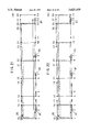
- FIGS. 35 and 36 show an example of a deadlock situation on travel grid 101:
- FIG. 35 is a transport diagram showing the initial state; and
- FIG. 36 is a transport diagram showing a deadlock state.
- unmanned vehicles which are not in a standby state are shown covered by crosshatches, while those unmanned vehicles in a standby state are shown within a white enclosure.
- the travel routes of unmanned vehicles #1 to #6 are as follows:
- unmanned vehicles #1 to #6 move only one interval from their initial routing shown in FIG. 35, a deadlock state as shown in FIG. 36 occurs.
- unmanned vehicles #2 and #5 are both in standby states, however, it is not possible to find a relief route as described in the aforementioned.
- An examination is then conducted on the obstructive unmanned vehicles with regard to each of unmanned vehicles #1 to #6; these results are shown in FIG. 37.
- unmanned vehicle #2 is considered an obstruction to unmanned vehicle #1, and node 6 is recognized as a potential relief node to which unmanned vehicle #1 can move during deadlock. Based on this result, the following four loops of unmanned vehicles which are current obstructions or potential obstructions are then obtained:
- loop 4 contains the most unmanned vehicles, and is thus selected as the competitive loop. Furthermore, in the aforementioned, () contains the current position (node) of each unmanned vehicle during deadlock.
- step Sc2 the number of unmanned vehicles to pass through the current nodes of the non-standby unmanned vehicles belonging to the competitive group are counted.
- step Sc3 an examination is conducted as to whether or not this aforementioned passage count is "0"; in the case when this count is "0", the present procedure ends (step Sc9); and in the case when this count is not "0", the procedure moves to subsequent Sc4.
- step Sc5 an examination is performed as to whether or not the unmanned vehicle will pass through the current node of an unmanned vehicle which is obstructing it; in the case when there is no passage, the procedure moves to Sc6; and in the case when there is passage, the procedure ends (step Sc9).
- this step is for the purpose of checking their meeting point (node).
- step Sc6 an evaluation value is assigned to the passage number resulting from step Sc2. At the time when a particular unmanned vehicle is being blocked by another unmanned vehicle in a standby state, this evaluation value is brought forth. In addition, the procedure comprising the aforementioned steps Sc2 to Sc6 is conducted on all nodes which are occupied by non-standby unmanned vehicles contained in the competitive loop.
- step Sc7 the node with the minimum evaluation value from among the nodes searched in step Sc6 is selected as the competitive node.
- step Sc8 data designating the initial passage of the unmanned vehicle which would potentially block the unmanned vehicle occupying the competitive node is added to the transition ignition control data.
- This transition ignition control data regulates the movement sequence of an unmanned vehicle at a specific node, and hence, the transition ignition is regulated by means of this data.
- FIGS. 39 and 40 show the final result of this aforementioned concrete example;
- FIG. 39 shows the routes of unmanned vehicles #1 to #6 from departure node to target node; and
- FIG. 40 shows the node reservation sequence.
- the target node is shown in (), and any route appearing after this node serves as the aforementioned relief route.
- the node reservation sequence shown in FIG. 40 indicates the sequence in which an unmanned vehicle reserves each node; for example, in this Figure, node 5 is reserved in order, first by unmanned vehicle #2 and then by unmanned vehicle #1.
- step Sd2 an examination is conducted as to whether or not a potential detour node (movable neighboring node) exists with regard to a standby unmanned vehicle belonging to the competitive group.
- a potential detour node movable neighboring node
- the procedure moves to step Sd3; and in the case when this type of node does not exist, the present procedure ends due to a detour route search failure (step Sd9).
- step Sd3 passage over the following arcs is temporarily prohibited with regard to the unmanned vehicle selected in the previous step.
- step Sd4 the present node is designated as the departure node, and the subsequent node is designated as the target node.
- step Sd5 a route-search procedure is conducted based on the designations of steps Sd3 and 4 (step Sa1).
- step Sd6 passage prohibition (no passage) of the arcs conducted in step Sd3 is canceled.
- step Sd7 an examination is conducted as to whether or not a detour route has been found in the route search procedure of step Sd5; in the case when a detour route exists, the procedure moves to the subsequent step Sd8; and in the case when a detour route does not exist, the present procedure ends due to a detour route search failure (Sd9).
- step Sd8 the route of the interval in question is exchanged for the detour route, and the present procedure is then completed (step Sd9).
- FIG. 42 is a transport diagram showing another example of a deadlock situation. Based on this figure, the aforementioned detour route search procedure will be explained in the following.
- the arcs from node 4 f 3 and node 4 f 18 are designated as "no passage", and a search is conducted for a detour route.
- the route of node 5 ⁇ 6 ⁇ 20 ⁇ 19 ⁇ 18 ⁇ 17 ⁇ . . . can be considered as a detour route for unmanned vehicle #1; however, since the arc from node 18 ⁇ 17 runs opposite to the route of unmanned vehicle #4, this route is fundamentally not chosen.
- this aforementioned route may be selected, since passage over an inverse interval therein is not prohibited.
- a route containing node 3 ⁇ 2 ⁇ 1 ⁇ 15 ⁇ 16 is obtained. This route then becomes the detour route, and is inserted into the route of unmanned vehicle #2 (3 ⁇ 16) as shown in FIG. 43.
- an appropriate unmanned vehicle is re-routed to a separate node (passing node), and after giving the right-of-way to another unmanned vehicle, returns to its original route.
- the passing route search which shows these passing operations is shown in FIG. 44, and will be explained in greater detail below.
- step Se1 a search is conducted with regard to an unmanned vehicle (non-standby unmanned vehicle) belonging to the competitive loop which has not yet reached its target node, as to whether or not an neighboring node exits (potential passing node) to which it can move; in the case when this type of node exists, the procedure moves to step Se3; and in the ease when this node does not exist, the present procedure ends due to a passing route search failure (Se10).
- step Se3 passage over the are from the present node to the subsequent node of this unmanned vehicle is temporarily prohibited.
- step Se4 the present node is designated as the departure node, while all other nodes are designated as target nodes.
- step Se5 under the conditions designated in steps Se3 and step Se4, the route search procedure (step Sa1) is performed.
- step Se6 from among the routes obtained in step Se5, the route with the minimum cost is selected, and the target node therein is designated as the passing node. However, in the selection of a passing node, all nodes existing in a single line interval are excluded.
- step Se7 the "no-passage" designation performed in step Se3 is canceled.
- step Se8 based on the result from step Se6, in the ease when a passing node does not exist, the present procedure ends due to a passing route search failure (step Se10); in the case when a passing node exists, the procedure moves on to the subsequent Se9.
- step Se9 the route from the present node to the passing node, as well as the route from the passing node back to the present node (passing route) is inserted into the present route, and the present procedure is then completed.
- FIG. 45 is a transport diagram showing an example of a deadlock situation; in the following, an explanation will be provided with regard to the passing route search procedure based on this figure.
- node 5 is selected as the passing node with the minimum cost.
- node 18 is also possible; however, due to cost considerations, the node with the lower cost, i.e., node 5 is selected as the passing node (see FIG. 2).
- a search is conducted for a route from node 5 to node 4, and node 4 ⁇ 5 ⁇ 4 is then recognized as a passing route.
- this passing route is inserted into the original route, and the overall route of unmanned vehicle #1 (node 4 ⁇ 5 ⁇ 4 ⁇ 3 ⁇ 2) is then obtained as shown in FIG. 46.
- Operational planning portion 108 determines the route of all of the unmanned vehicles and also plans their movement sequences using the aforementioned procedures (1) to (6). This operational planning procedure will be explained in greater detail below based on the flow charts shown in FIGS. 47, 48, and 49.
- step Sf1 a model of the travel route is formed using a Petri net.
- step Sf2 the trial cycle is set to "1".
- step Sf3 the route of each unmanned vehicle is set into the standard routing obtained by means of the route planning.
- step Sf4 the trial cycle is examined; in the case when the trial cycle is "1", the procedure moves on to the subsequent step Sf5; however, when this value is a number other than "1", the procedure skips to step Sf6.
- step Sf5 passage over all arcs running opposite to the routes of the standard routing above is prohibited. In this manner, there is no generation of inverse intervals due to the subsequent procedure.
- step Sf5 is not executed, and the aforementioned passage prohibition is not executed in the route search procedure.
- step Sf 6 the present time is reset to "0".
- step S7 the respective unmanned vehicles are placed at their respective departure points, and from the routes therein, the ignition projected transition series are calculated, respectively.
- step Sf8 the completion time of each unmanned vehicle is reset to "1".
- step Sf9 the ignition transition series is opened and reset to the beginning.
- This ignition transition series is in actuality the series of transitions in which ignition occurs, and is not always the same as the ignition projected transition series.
- step Sf10 the completion time of each unmanned vehicle is checked against the present time; in the case when these times are equal, the procedure moves to step Sf11; however, in the case when these times differ, the procedure branches off to step Sf12.
- step Sf11 the lead transition is read out from the ignition projected transitions of all vehicles satisfying the conditions of step Sf10, and an ignition completion procedure is conducted.
- step Sf12 the completion time of each unmanned vehicle is checked with the present time: if a completion time precedes or equals the present time, the procedure moves to step Sf13; however, if the completion time follows the present time, the procedure branches off to step Sf20.
- step Sf13 an examination is performed as to whether or not the lead transition of the ignition of the ignition projected transitions is ignitable; in the case when this transition is ignitable, the procedure moves to step Sf14; however, in the case when this transition is not ignitable, the procedure branches off to step Sf17.
- an ignition procedure is performed by reading out all transitions which are determined to be ignitable in step Sf13.
- step Sf15 the completion time is recalculated by adding the movement time of the ignited transition to the original completion time.
- step Sf16 the transitions in which the ignition procedure of Sf14 was carried out are registered (added) to each respective corresponding ignition transition series, after which the procedure moves to Sf20.
- step Sf17 an examination is carried out as to whether or not neighboring nodes exist to which obstructive unmanned vehicles corresponding to the non-ignitable transitions can move.
- an examination is conducted as to whether obstructive unmanned vehicles can be displaced to other nodes or not.
- the procedure moves to the subsequent step Sf18; however, when this displacement is not possible, the procedure branches off to step Sf20.
- step Sf18 the unmanned vehicles which are determined to be displaceable in step Sf17 are checked to determine whether they are in a standby state or not.
- the procedure moves to step Sf19; however, in the case when a vehicle is not in a standby state, the procedure branches to step Sf20.
- step Sf19 a search for a relief route is performed with regard to an unmanned vehicle which meets both conditions of step Sf17 and step Sf18 (FIG. 32, step Sa1).
- step Sf20 an examination is conducted as to whether or not the completion times of ignition transitions corresponding to all of the unmanned vehicles precede or equal the present time; in the case when this result is "yes”, the procedure branches off to step 22; and when the result of this examination is "no", the procedure moves to step Sf21.
- step Sf21 the completion time of the unmanned vehicle with the closest completion time from among all unmanned vehicles is set to the present time, following which, the procedure moves to step Sf10 (FIG. 47).
- step Sf22 an examination is conducted as to whether or not the ignition projected transition series of all unmanned vehicles is open; in the case when this result is "yes”, the procedure branches off to step Sf32 (FIG. 49); however, when the result of this examination is "no", the procedure moves on to the subsequent step Sf23.
- step Sf23 the deadlock situation is checked by means of the aforementioned deadlock recognition procedure (FIG. 34, step Sb1).
- step Sf24 the ignition sequence of each transition is adjusted by means of the aforementioned transition sequence adjusting procedure (FIG. 38, step Sc1) based on the competitive loop obtained by the procedure of step Sf23.
- step Sf25 an examination is conducted as to whether or not the adjustment of the ignition sequence conducted in step Sf24 was successful; in the case when this adjustment failed, the procedure moves to step Sf26; and in the case when this adjustment was successful. i.e., the deadlock situation was solved, the procedure returns to step Sf6 (FIG. 47).
- step Sf26 a search is conducted for a detour route according to the detour route search procedure mentioned above (FIG. 41, step Sd1).
- step Sf27 a determination is made as to whether this detour route search in the previous step was successful or not; in the case when this search failed, the procedure moves on to the subsequent step step Sf28; and in the case when this search was successful, the procedure returns to step Sf6 (FIG. 47).
- step Sf28 a search is conducted for a passing route according to the aforementioned passing route search (FIG. 44, step Se1).
- step Sf29 a determination is made as to whether this passing route search of the previous step was successful or not; in the case when this search failed, the procedure moves on to the subsequent step Sf30; and in the case when this search was successful, the procedure returns to step Sf6 (FIG. 47).
- step Sf30 the current trial cycle is examined; in the case when this cycle is "1", the procedure moves on the subsequent step Sf31; and in the case when this value is other than "1", the entire procedure is ended due to an operational planning failure (step Sf34).
- step Sf31 the trial cycle is increased to "2", following which the procedure returns to step Sf3 (FIG. 47).
- Step Sf32 is executed in the case when the operational planning of the unmanned vehicle was successful; in this step, the present route is designated as the final routing of the unmanned vehicle.
- step Sf33 the ignition transition series and sequence of unmanned vehicles occupying each node (node reservation sequence) are formed, following which the entire procedure ends (step Sf34).
- FIGS. 50 to 56 are Petri net diagrams showing this type of simulation.
- transitions T23 and T67 corresponding to unmanned vehicles #1 and #2, respectively, are ignited by means of the ignition procedure described above (step Sf14).
- the completion times of the aforementioned transitions are 1 and 2 seconds, respectively; and a white token is placed on each of presses P3 and P4.
- step Sf21 the present time is renewed to 1 second, i.e., the completion time of unmanned vehicle #1, and the procedure then returns to step Sf10.
- a black token and a white token are then removed from presses P2 and P3, respectively, by means of the ignition completion procedure of step Sf11, following which a black token appears on press P3 as shown in FIG. 51.
- This state indicates that unmanned vehicle #1 has reached node 3.
- transition T67 which is currently in a state of ignition, takes the form of a rectangle.
- transition T34 corresponding to unmanned vehicle #1 is ignited in step Sf14, following which the completion time of unmanned vehicle #1 is set to 4 seconds by means of step Sf15.
- step Sf21 the present time is renewed to 3 seconds, i.e., the completion time of unmanned vehicle #2, and the procedure then returns to step Sf11, passing en route through step Sf10, at which point an ignition completion procedure is performed on transition T67.
- step Sf13 transition T73 of unmanned vehicle #2 is examined; however, due to the presence of a black token on press P3 of the output destination, this transition cannot be ignited. This is a result of unmanned vehicle #1 occupying node 3. Unmanned vehicle #1 is currently en route from present node 3 to node 4, and thus cannot be displaced. As a result, unmanned vehicle #2 must wait at node 7, and in step Sf21, the present time is renewed to 4 seconds, i.e., the completion time of unmanned vehicle #1.
- step Sf14 after transition T34 is ignited, unmanned vehicle #1 arrives at target node 4. Subsequently, unmanned vehicle #1 releases node 3, thus allowing the ignition of transition T73 in step Sf14 as shown in FIG. 53.
- step Sf19 a relief route for unmanned vehicle #1 (node 4 ⁇ 8) is found by means of the above-described relief route search procedure, and the corresponding transition T48 is added to the transition to be ignited, and then ignited.
- unmanned vehicles #1 and #2 correspond to the solid and short-dashed lines, respectively.
- the arrows represent the movements of each unmanned vehicle, and the horizontal lines indicate the time period of reservation. For example, unmanned vehicle #1 moves from node 2 to node 3 in 1 second, and then moves to node 4 over the course of 3 seconds. During this interval, node 3 is reserved by unmanned vehicle #1 over the time course from 0 to 4.
- transport management control apparatus 102 (FIG. 1) in carrier grid 101 shown in FIG. 1 will be explained.
- parts corresponding to those shown in FIG. 1 will be denoted by the same numerals and their descriptions will be omitted.
- departure points and target points in this operational example are shown in FIG. 59.
- route planning portion 109 outputs a search designation (FIG. 59) to route search portion 110.
- Route search portion 110 searches for the carrier route (initial route) of each unmanned vehicle #1 to #5 in accordance with the search designation, and then outputs this initial routing to route planning portion 109.
- FIG. 62 is a transport diagram showing this aforementioned initial routing: in the same figure, the routes of unmanned vehicles #1 to #7 are represented by a dotted line, long single-dotted chain line, double-dotted chain line, single-dotted chain line, short-dashed line, solid line and long-short-dashed line, respectively.
- route planning portion 109 recognizes the intervals between nodes 2 to 3, nodes 4 to 6 and nodes 8 to 10 as inverse intervals. As a result, route planning portion 109 conducts orientation of specific intervals on the travel grid with respect to cost, and then outputs a search designation again to route search portion 110. The aforementioned operations are performed until all inverse intervals have been removed to obtain the standard routing shown in FIG. 60 and FIG. 62. Route planning portion 109 then outputs this standard routing to operation planning portion 108.
- Route planning portion 108 subsequently conducts the above-described operational planning procedure (FIGS. 47, 48, and 49) based on this standard routing.
- route searches e.g. detour route and the like, are conducted during the aforementioned procedure in route search portion 10 via route planning portion 109.
- operational planning portion 108 outputs the departure nodes, target nodes, and "no-passage" intervals.
- FIG. 61 and FIG. 64 are obtained.
- the relief route of unmanned vehicle #1 (node 20 f 6) has been added to the standard routing shown in FIG. 60.
- FIG. 65 is a transport diagram showing the timed movements of unmanned vehicles #1 to #7 at this time.
- FIG. 67 and FIG. 70 are then formed in operational planning portion 108.
- the relief route of unmanned vehicle #1 node 20 ⁇ 6
- the relief route of unmanned vehicle #5 node 8 ⁇ 22 ⁇ 23 ⁇ 24 ⁇ 10 ⁇ 9
- FIG. 7 is the corresponding transport diagram: in this figure, the node reservation of unmanned vehicles #1 to #7 are shown by the same lines as in FIG. 65.
- the travel routes and travel sequences of all of the unmanned vehicles can be obtained before movement commences by previously taking into consideration potential obstructions caused by certain unmanned vehicles. Therefore, a plurality of unmanned vehicles can move smoothly over a travel grid even in the case when the potential for frequent interferences exist. Consequently, the carrier efficiency of the unmanned vehicles can be improved.
- FIG. 72 is a block diagram showing an optimal route determining apparatus in accordance with the present embodiment; parts which are identical to those in FIG. 7 are given identical reference numbers, and an explanation thereof will be omitted.
- graph generator 8 generates graph G shown below.
- static graph generator 10 calculates the cost B ij of each arc by means of formulas (2), (4), or (5).
- angular potential calculator 11 calculates an angular potential cost T ij (g) by means of formulas (8) and (9) below, with respect to each arc.
- K is a prospecified coefficient
- ABS() is the abstract value of ()
- formula (8) exhibits the remainder in the case in which ABS(q(g, j)-q(g, i)) is divided by p.
- the angular difference between the direction of the node i, as seen from the target node g, and the x axial direction, and the angular difference between the direction of the node j, as seen from the target node g, and the x axial direction are calculated.
- coefficients which are set based on the difference between these angular differences are multiplied by the cost B ij , and a new cost T ij (g) is calculated.
- the set C ij (g) of the arc costs is set depending on the target node, in addition to the initial point node and final point node of each arc.
- Optimal route generator 9 receives the carrying directives from the central unit, and determines the departure node and the target node, as in the conventional art. Then, based on this, the graph G discussed above which was determined in graph generator 8, and the mapped data and unmanned carrier vehicle data, this optimal route generator 9 generates an optimal route which minimizes estimated costs.
- the angular potential calculator 11 calculates the angular potential costs T ij (28) which are shown in FIG. 73.
- the coefficient K has a value of "1".
- cost B ij and the angular potential cost T ij (28) are added with respect to each arc, and the result is stored in the search graph data memory 12 as cost C ij (28).
- the calculation results of the costs C ij (28) are shown in FIG. 74.
- the cost B ij and the angular potential cost T ij (100) are calculated in an identical manner to that described above, and the cost C ij (100), representing a summation of these two, is stored in search graph data memory 12.
- the calculation results of the costs C ij (100) are shown in FIG. 75.
- the unmanned carrier vehicles mainly travel in the horizontal direction, and furthermore, stations for the unloading of work are disposed in the vertical direction of the travel grid. Furthermore, in the case in which a plurality of unmanned carrier vehicles are traveling along this type of thin and long travel grid, if the vehicles are caused to travel as much as possible along the outer side, the risk of mutual interference is the least.
- the positioning at the stations is the most accurate if the greatest distance possible is traveled in the horizontal direction prior to the target node.
- the shortest routes which were determined all exhibited the tendency to consist of continuous horizontal or vertical arcs.
- routes running along the outer side of the travel grid are liable to be selected. This is the result of weighting with an angular potential cost, and accordingly, it is possible to determine shortest routes which will satisfy the desires in the operational environments described above.
- the embodiment shown in FIG. 72 can be applied for the transport management control apparatus in order to determine the optimal routes of the unmanned vehicle.
- graph generator 8 and optimal route generator 9 shown in FIG. 72 may be employed in route search portion 110 shown in FIG. 15.
- Data stored in map data memory 16 and unmanned carrier vehicle data memory 18 in FIG. 17 may be stored in unmanned vehicle data memory 105 and travel grid data memory 106 in FIG. 15.
- the unmanned travel vehicles travel along travel routes which have a grid shape (travel grid).
- the present invention can be applied to the other unmanned travel vehicle systems which use travel routes not having a grid shape.
Landscapes
- Engineering & Computer Science (AREA)
- Radar, Positioning & Navigation (AREA)
- Physics & Mathematics (AREA)
- Remote Sensing (AREA)
- General Physics & Mathematics (AREA)
- Automation & Control Theory (AREA)
- Aviation & Aerospace Engineering (AREA)
- General Engineering & Computer Science (AREA)
- Manufacturing & Machinery (AREA)
- Quality & Reliability (AREA)
- Acoustics & Sound (AREA)
- Control Of Position, Course, Altitude, Or Attitude Of Moving Bodies (AREA)
Priority Applications (1)
| Application Number | Priority Date | Filing Date | Title |
|---|---|---|---|
| US08/493,783 US5625559A (en) | 1993-04-02 | 1995-06-22 | Transport management control apparatus and method for unmanned vehicle system |
Applications Claiming Priority (8)
| Application Number | Priority Date | Filing Date | Title |
|---|---|---|---|
| JP7724493A JP3031109B2 (ja) | 1993-04-02 | 1993-04-02 | 最適経路決定装置 |
| JP5-077244 | 1993-04-02 | ||
| JP31093293 | 1993-12-10 | ||
| JP5-310932 | 1993-12-10 | ||
| JP5310931A JP2953282B2 (ja) | 1993-12-10 | 1993-12-10 | 運行管理制御装置およびその方法 |
| JP5-310931 | 1993-12-10 | ||
| US22054194A | 1994-03-30 | 1994-03-30 | |
| US08/493,783 US5625559A (en) | 1993-04-02 | 1995-06-22 | Transport management control apparatus and method for unmanned vehicle system |
Related Parent Applications (1)
| Application Number | Title | Priority Date | Filing Date |
|---|---|---|---|
| US22054194A Continuation | 1993-04-02 | 1994-03-30 |
Publications (1)
| Publication Number | Publication Date |
|---|---|
| US5625559A true US5625559A (en) | 1997-04-29 |
Family
ID=27302376
Family Applications (1)
| Application Number | Title | Priority Date | Filing Date |
|---|---|---|---|
| US08/493,783 Expired - Fee Related US5625559A (en) | 1993-04-02 | 1995-06-22 | Transport management control apparatus and method for unmanned vehicle system |
Country Status (3)
| Country | Link |
|---|---|
| US (1) | US5625559A (fr) |
| EP (1) | EP0618523B1 (fr) |
| DE (1) | DE69415067T2 (fr) |
Cited By (55)
| Publication number | Priority date | Publication date | Assignee | Title |
|---|---|---|---|---|
| US5928294A (en) * | 1994-02-03 | 1999-07-27 | Zelinkovsky; Reuven | Transport system |
| US6246932B1 (en) * | 1997-02-20 | 2001-06-12 | Komatsu Ltd. | Vehicle monitor for controlling movements of a plurality of vehicles |
| US6484078B1 (en) * | 1999-10-26 | 2002-11-19 | Komatsu Ltd. | Vehicle travel route control system |
| WO2003010614A1 (fr) * | 2001-07-24 | 2003-02-06 | Honda Giken Kogyo Kabushiki Kaisha | Procede et systeme pour la gestion des mouvements de vehicules de transfert |
| KR100506926B1 (ko) * | 2003-07-16 | 2005-08-09 | 삼성전자주식회사 | 단일경로용 작업시스템 및 그 제어방법 |
| CN1294527C (zh) * | 2003-02-10 | 2007-01-10 | 三星电子株式会社 | 用于输送系统的布置建模系统 |
| US20070016363A1 (en) * | 2005-07-15 | 2007-01-18 | Oracle International Corporation | Interactive map-based user interface for transportation planning |
| US7219067B1 (en) | 1999-09-10 | 2007-05-15 | Ge Harris Railway Electronics Llc | Total transportation management system |
| EP1840689A2 (fr) * | 2006-03-30 | 2007-10-03 | Honeywell International Inc. | Planification et établissement du programme en temps réel pour une équipe de véhicules autonomes |
| US20070260369A1 (en) * | 2006-05-02 | 2007-11-08 | Philp Joseph W | Method and apparatus for planning the movement of trains using dynamic analysis |
| US20070293978A1 (en) * | 2006-06-19 | 2007-12-20 | Wurman Peter R | System and method for transporting inventory items |
| US20070290040A1 (en) * | 2006-06-19 | 2007-12-20 | Wurman Peter R | System and method for maneuvering a mobile drive unit |
| US20070294029A1 (en) * | 2006-06-19 | 2007-12-20 | D Andrea Raffaello | System and method for managing mobile drive units |
| US20070293996A1 (en) * | 2005-12-09 | 2007-12-20 | Komatsu Ltd. | Travel control device and method for vehicles |
| WO2007149711A2 (fr) | 2006-06-19 | 2007-12-27 | Kiva Systems, Inc. | Système et procédé pour coordonner le déplacement d'unités de commande |
| US20080001372A1 (en) * | 2006-06-19 | 2008-01-03 | Hoffman Andrew E | System and method for positioning a mobile drive unit |
| US20080051984A1 (en) * | 2006-06-19 | 2008-02-28 | Wurman Peter R | System and method for generating a path for a mobile drive unit |
| US20100082194A1 (en) * | 2007-07-18 | 2010-04-01 | Hidenori Yabushita | Path planning device and method, cost evaluation device, and moving body |
| WO2010115673A1 (fr) * | 2009-04-06 | 2010-10-14 | Siemens Aktiengesellschaft | Routage dépendant de la charge dans des systèmes de flux de matériel |
| WO2010115704A1 (fr) * | 2009-04-06 | 2010-10-14 | Siemens Aktiengesellschaft | Système de flux de matériel décentralisé |
| US20100324771A1 (en) * | 2008-02-07 | 2010-12-23 | Toyota Jidosha Kabushiki Kaisha | Autonomous moving body, its control method, and control system |
| WO2009156931A3 (fr) * | 2008-06-26 | 2011-01-20 | Koninklijke Philips Electronics, N.V. | Procédé et système pour la planification précise de trajet |
| US20120330540A1 (en) * | 2009-11-09 | 2012-12-27 | Tomonori Ozaki | Apparatus and method for controlling travel of vehicles |
| WO2013173047A1 (fr) * | 2012-05-14 | 2013-11-21 | Amazon Technologies, Inc. | Système et procédé pour manœuvrer un élément moteur mobile |
| US8892240B1 (en) | 2011-06-29 | 2014-11-18 | Amazon Technologies, Inc. | Modular material handling system for order fulfillment |
| US20150025714A1 (en) * | 2013-06-28 | 2015-01-22 | SERVIS Intralogistics GmbH | Control systems for a rail-bound driving robot and procedures to operate |
| WO2015042587A3 (fr) * | 2013-09-23 | 2015-05-21 | Amazon Technologies Inc. | Transport entre entrepôts dans des systèmes d'exécution de commande et de gestion de stocks |
| US9057508B1 (en) | 2014-10-22 | 2015-06-16 | Codeshelf | Modular hanging lasers to enable real-time control in a distribution center |
| US9164512B2 (en) | 2009-11-27 | 2015-10-20 | Toyota Jidosha Kabushiki Kaisha | Autonomous moving body and control method thereof |
| US9262741B1 (en) | 2015-04-28 | 2016-02-16 | Codeshelf | Continuous barcode tape based inventory location tracking |
| US9327397B1 (en) | 2015-04-09 | 2016-05-03 | Codeshelf | Telepresence based inventory pick and place operations through robotic arms affixed to each row of a shelf |
| CN106547271A (zh) * | 2016-10-20 | 2017-03-29 | 大族激光科技产业集团股份有限公司 | Agv交通管制方法和装置 |
| CN106774305A (zh) * | 2016-11-30 | 2017-05-31 | 上海振华重工电气有限公司 | 自动化集装箱码头多自动引导车辆路径冲突消解方法 |
| US20180012160A1 (en) * | 2016-07-07 | 2018-01-11 | Sap Se | Integrated system for optimizing vehicle utilization |
| US20180113471A1 (en) * | 2016-10-26 | 2018-04-26 | Kubota Corporation | Travel route generating device and method for generating travel route |
| US20180299882A1 (en) * | 2017-04-12 | 2018-10-18 | X Development Llc | Roadmap Annotation for Deadlock-Free Multi-Agent Navigation |
| US20180329429A1 (en) * | 2016-03-11 | 2018-11-15 | Panasonic Intellectual Property Management Co., Lt d. | Automatic vehicle dispatching system and server device |
| CN110109448A (zh) * | 2018-02-01 | 2019-08-09 | 通用汽车环球科技运作有限责任公司 | 形成车队和在车队中定位车辆的系统和方法 |
| US10380886B2 (en) * | 2017-05-17 | 2019-08-13 | Cavh Llc | Connected automated vehicle highway systems and methods |
| US20200139964A1 (en) * | 2018-11-06 | 2020-05-07 | Kabushiki Kaisha Toshiba | Deadlock detection device, information processing device, deadlock detection method, and non-transitory computer readable medium |
| US10692365B2 (en) | 2017-06-20 | 2020-06-23 | Cavh Llc | Intelligent road infrastructure system (IRIS): systems and methods |
| US10723555B2 (en) | 2017-08-28 | 2020-07-28 | Google Llc | Robot inventory updates for order routing |
| US10867512B2 (en) | 2018-02-06 | 2020-12-15 | Cavh Llc | Intelligent road infrastructure system (IRIS): systems and methods |
| US11373122B2 (en) | 2018-07-10 | 2022-06-28 | Cavh Llc | Fixed-route service system for CAVH systems |
| US11397442B2 (en) | 2019-03-13 | 2022-07-26 | Kabushiki Kaisha Toshiba | Travel planning system, travel planning method, and non-transitory computer readable medium |
| US20220342423A1 (en) * | 2021-04-23 | 2022-10-27 | Daifuku Co., Ltd. | Article Transport Facility, Route Setting Method, and Route Setting Program |
| US11495126B2 (en) | 2018-05-09 | 2022-11-08 | Cavh Llc | Systems and methods for driving intelligence allocation between vehicles and highways |
| US11586221B2 (en) | 2020-03-16 | 2023-02-21 | Kabushiki Kaisha Toshiba | Travel control device, travel control method and computer program |
| US11635770B2 (en) | 2019-07-12 | 2023-04-25 | Murata Machinery, Ltd. | Traveling vehicle system and traveling vehicle control method |
| US11735041B2 (en) | 2018-07-10 | 2023-08-22 | Cavh Llc | Route-specific services for connected automated vehicle highway systems |
| US11735035B2 (en) | 2017-05-17 | 2023-08-22 | Cavh Llc | Autonomous vehicle and cloud control (AVCC) system with roadside unit (RSU) network |
| US11782446B2 (en) | 2018-11-22 | 2023-10-10 | Nec Corporation | Route planning apparatus, route planning method, and computer-readable recording medium |
| US11842642B2 (en) | 2018-06-20 | 2023-12-12 | Cavh Llc | Connected automated vehicle highway systems and methods related to heavy vehicles |
| US11860621B2 (en) | 2019-10-30 | 2024-01-02 | Kabushiki Kaisha Toshiba | Travel control device, travel control method, travel control system and computer program |
| US12057011B2 (en) | 2018-06-28 | 2024-08-06 | Cavh Llc | Cloud-based technology for connected and automated vehicle highway systems |
Families Citing this family (13)
| Publication number | Priority date | Publication date | Assignee | Title |
|---|---|---|---|---|
| GB2314171A (en) * | 1996-06-14 | 1997-12-17 | Post Office | Automated portering system |
| DE19629618A1 (de) * | 1996-07-23 | 1998-01-29 | Claas Ohg | Routenplanungssystem für landwirtschaftliche Arbeitsfahrzeuge |
| JP3653954B2 (ja) * | 1997-10-23 | 2005-06-02 | トヨタ自動車株式会社 | 移動体交通制御システムの移動体装置、移動体交通制御システムの管制局、移動体交通制御システム |
| WO2001001369A1 (fr) * | 1999-06-25 | 2001-01-04 | Daimlerchrysler Ag | Procede de commande d'unites de transport dans un reseau de circulation |
| DE102013207895A1 (de) | 2013-04-30 | 2014-10-30 | Kuka Laboratories Gmbh | Fahrerloses Transportfahrzeug, System mit einem Rechner und einem fahrerlosen Transportfahrzeug, Verfahren zum Betreiben eines fahrerlosen Transportfahrzeugs |
| DE102013207899A1 (de) * | 2013-04-30 | 2014-10-30 | Kuka Laboratories Gmbh | Fahrerloses Transportfahrzeug, System mit einem Rechner und einem fahrerlosen Transportfahrzeug, Verfahren zum Planen einer virtuellen Spur und Verfahren zum Betreiben eines fahrerlosen Transportfahrzeugs |
| CN104134356B (zh) * | 2014-06-30 | 2017-02-01 | 南京航空航天大学 | 城市交叉口模型参考自适应信号的控制方法 |
| AU2016384096B2 (en) * | 2016-01-04 | 2019-10-24 | Zhejiang Libiao Robots Co., Ltd. | Method and device for returning robots from site |
| CN105931474A (zh) * | 2016-02-29 | 2016-09-07 | 南京航空航天大学 | 一种带有量子决策的防止城市道路交叉口群的局部溢流控制方法 |
| CN107678405B (zh) * | 2017-08-22 | 2020-01-31 | 广东美的智能机器人有限公司 | 机器人行驶方法及其装置 |
| FR3091592B1 (fr) | 2019-01-04 | 2021-01-29 | Balyo | Procédé pour la commande par un serveur de supervision du déplacement d’une flotte de véhicules à guidage autonome |
| CN109724612B (zh) * | 2019-01-14 | 2021-06-15 | 浙江华睿科技有限公司 | 一种基于拓扑地图的agv路径规划方法及设备 |
| CN112987711B (zh) * | 2019-11-30 | 2022-08-09 | 华为技术有限公司 | 自动驾驶规控算法优化方法及仿真测试装置 |
Citations (12)
| Publication number | Priority date | Publication date | Assignee | Title |
|---|---|---|---|---|
| US4023753A (en) * | 1974-11-22 | 1977-05-17 | International Standard Electric Corporation | Vehicle control system |
| US4361300A (en) * | 1980-10-08 | 1982-11-30 | Westinghouse Electric Corp. | Vehicle train routing apparatus and method |
| EP0213939A2 (fr) * | 1985-08-30 | 1987-03-11 | Texas Instruments Incorporated | Contrôleur pour un véhicule mobile utilisant les dates absolues retardées de position pour le guidage et la navigation |
| EP0341889A2 (fr) * | 1988-05-13 | 1989-11-15 | Cegelec Controls Ltd. | Commande automatique de véhicule |
| DE3930425A1 (de) * | 1988-09-13 | 1990-03-22 | Tsubakimoto Chain Co | Verfahren zum dirigieren des laufs eines sich bewegenden objekts |
| EP0367527A2 (fr) * | 1988-10-31 | 1990-05-09 | Texas Instruments Incorporated | Méthode de contrôle du mouvement d'un robot mobile dans une usine à repères multiples |
| DE4013188A1 (de) * | 1989-05-02 | 1990-11-08 | Minnesota Mining & Mfg | Edelmetall-polymer-verbundmaterialien und daraus hergestellte flexible duennfilmleiter |
| US4974259A (en) * | 1987-12-09 | 1990-11-27 | Fuji Electric Co., Ltd. | Control system for unattended transport car |
| JPH02309406A (ja) * | 1989-05-24 | 1990-12-25 | Shinko Electric Co Ltd | 移動ロボットシステムにおける走行制御方法 |
| JPH04340607A (ja) * | 1991-05-17 | 1992-11-27 | Shinko Electric Co Ltd | 最適経路決定装置 |
| US5257363A (en) * | 1990-04-09 | 1993-10-26 | Meta Software Corporation | Computer-aided generation of programs modelling complex systems using colored petri nets |
| US5297049A (en) * | 1982-11-08 | 1994-03-22 | Hailemichael Gurmu | Vehicle guidance system |
Family Cites Families (1)
| Publication number | Priority date | Publication date | Assignee | Title |
|---|---|---|---|---|
| US5179329A (en) * | 1989-04-25 | 1993-01-12 | Shinko Electric Co., Ltd. | Travel control method, travel control device, and mobile robot for mobile robot systems |
-
1994
- 1994-04-01 DE DE69415067T patent/DE69415067T2/de not_active Expired - Fee Related
- 1994-04-01 EP EP94400723A patent/EP0618523B1/fr not_active Expired - Lifetime
-
1995
- 1995-06-22 US US08/493,783 patent/US5625559A/en not_active Expired - Fee Related
Patent Citations (13)
| Publication number | Priority date | Publication date | Assignee | Title |
|---|---|---|---|---|
| US4023753A (en) * | 1974-11-22 | 1977-05-17 | International Standard Electric Corporation | Vehicle control system |
| US4361300A (en) * | 1980-10-08 | 1982-11-30 | Westinghouse Electric Corp. | Vehicle train routing apparatus and method |
| US5297049A (en) * | 1982-11-08 | 1994-03-22 | Hailemichael Gurmu | Vehicle guidance system |
| EP0213939A2 (fr) * | 1985-08-30 | 1987-03-11 | Texas Instruments Incorporated | Contrôleur pour un véhicule mobile utilisant les dates absolues retardées de position pour le guidage et la navigation |
| US4974259A (en) * | 1987-12-09 | 1990-11-27 | Fuji Electric Co., Ltd. | Control system for unattended transport car |
| EP0341889A2 (fr) * | 1988-05-13 | 1989-11-15 | Cegelec Controls Ltd. | Commande automatique de véhicule |
| US5038290A (en) * | 1988-09-13 | 1991-08-06 | Tsubakimoto Chain Co. | Managing method of a run of moving objects |
| DE3930425A1 (de) * | 1988-09-13 | 1990-03-22 | Tsubakimoto Chain Co | Verfahren zum dirigieren des laufs eines sich bewegenden objekts |
| EP0367527A2 (fr) * | 1988-10-31 | 1990-05-09 | Texas Instruments Incorporated | Méthode de contrôle du mouvement d'un robot mobile dans une usine à repères multiples |
| DE4013188A1 (de) * | 1989-05-02 | 1990-11-08 | Minnesota Mining & Mfg | Edelmetall-polymer-verbundmaterialien und daraus hergestellte flexible duennfilmleiter |
| JPH02309406A (ja) * | 1989-05-24 | 1990-12-25 | Shinko Electric Co Ltd | 移動ロボットシステムにおける走行制御方法 |
| US5257363A (en) * | 1990-04-09 | 1993-10-26 | Meta Software Corporation | Computer-aided generation of programs modelling complex systems using colored petri nets |
| JPH04340607A (ja) * | 1991-05-17 | 1992-11-27 | Shinko Electric Co Ltd | 最適経路決定装置 |
Non-Patent Citations (4)
| Title |
|---|
| Patent Abstracts of Japan, vol. 15, No. 99 (P 1177) 11 Mar. 1991 & JP A 02 309 406 (English abstract enclosed). * |
| Patent Abstracts of Japan, vol. 15, No. 99 (P-1177) 11 Mar. 1991 & JP-A-02 309 406 (English abstract enclosed). |
| Patent Abstracts of Japan, vol. 17, No. 189 (P 1521) 13 Apr. 1993 & JP A 04 340 607 (English abstract enclosed). * |
| Patent Abstracts of Japan, vol. 17, No. 189 (P-1521) 13 Apr. 1993 & JP-A-04 340 607 (English abstract enclosed). |
Cited By (133)
| Publication number | Priority date | Publication date | Assignee | Title |
|---|---|---|---|---|
| US5928294A (en) * | 1994-02-03 | 1999-07-27 | Zelinkovsky; Reuven | Transport system |
| US6246932B1 (en) * | 1997-02-20 | 2001-06-12 | Komatsu Ltd. | Vehicle monitor for controlling movements of a plurality of vehicles |
| US7219067B1 (en) | 1999-09-10 | 2007-05-15 | Ge Harris Railway Electronics Llc | Total transportation management system |
| US6484078B1 (en) * | 1999-10-26 | 2002-11-19 | Komatsu Ltd. | Vehicle travel route control system |
| WO2003010614A1 (fr) * | 2001-07-24 | 2003-02-06 | Honda Giken Kogyo Kabushiki Kaisha | Procede et systeme pour la gestion des mouvements de vehicules de transfert |
| GB2394319A (en) * | 2001-07-24 | 2004-04-21 | Honda Motor Co Ltd | Work transfer method and system |
| US20040254674A1 (en) * | 2001-07-24 | 2004-12-16 | Satoshi Nojo | Work transfer method and system |
| GB2394319B (en) * | 2001-07-24 | 2005-06-22 | Honda Motor Co Ltd | Work transfer method and system |
| CN1294527C (zh) * | 2003-02-10 | 2007-01-10 | 三星电子株式会社 | 用于输送系统的布置建模系统 |
| KR100506926B1 (ko) * | 2003-07-16 | 2005-08-09 | 삼성전자주식회사 | 단일경로용 작업시스템 및 그 제어방법 |
| US20070016363A1 (en) * | 2005-07-15 | 2007-01-18 | Oracle International Corporation | Interactive map-based user interface for transportation planning |
| US7742853B2 (en) * | 2005-12-09 | 2010-06-22 | Komatsu Ltd. | Travel control device and method for vehicles |
| US20070293996A1 (en) * | 2005-12-09 | 2007-12-20 | Komatsu Ltd. | Travel control device and method for vehicles |
| EP1840689A3 (fr) * | 2006-03-30 | 2009-09-23 | Honeywell International Inc. | Planification et établissement du programme en temps réel pour une équipe de véhicules autonomes |
| EP1840689A2 (fr) * | 2006-03-30 | 2007-10-03 | Honeywell International Inc. | Planification et établissement du programme en temps réel pour une équipe de véhicules autonomes |
| US20070260369A1 (en) * | 2006-05-02 | 2007-11-08 | Philp Joseph W | Method and apparatus for planning the movement of trains using dynamic analysis |
| US7734383B2 (en) * | 2006-05-02 | 2010-06-08 | General Electric Company | Method and apparatus for planning the movement of trains using dynamic analysis |
| US20110112758A1 (en) * | 2006-06-19 | 2011-05-12 | Kiva Systems, Inc. | System and Method for Managing Mobile Drive Units |
| US8265873B2 (en) | 2006-06-19 | 2012-09-11 | Kiva Systems, Inc. | System and method for managing mobile drive units |
| US20080051984A1 (en) * | 2006-06-19 | 2008-02-28 | Wurman Peter R | System and method for generating a path for a mobile drive unit |
| US20080051985A1 (en) * | 2006-06-19 | 2008-02-28 | D Andrea Raffaello | System and method for coordinating movement of mobile drive units |
| WO2007149711A3 (fr) * | 2006-06-19 | 2008-05-22 | Kiva Sys Inc | Système et procédé pour coordonner le déplacement d'unités de commande |
| WO2007149711A2 (fr) | 2006-06-19 | 2007-12-27 | Kiva Systems, Inc. | Système et procédé pour coordonner le déplacement d'unités de commande |
| US9511934B2 (en) | 2006-06-19 | 2016-12-06 | Amazon Technologies, Inc. | Maneuvering a mobile drive unit |
| US20070294029A1 (en) * | 2006-06-19 | 2007-12-20 | D Andrea Raffaello | System and method for managing mobile drive units |
| US20070290040A1 (en) * | 2006-06-19 | 2007-12-20 | Wurman Peter R | System and method for maneuvering a mobile drive unit |
| US9519284B2 (en) | 2006-06-19 | 2016-12-13 | Amazon Technologies, Inc. | Transporting inventory items using mobile drive units and conveyance equipment |
| US9740212B2 (en) * | 2006-06-19 | 2017-08-22 | Amazon Technologies, Inc. | System and method for coordinating movement of mobile drive units |
| US20070293978A1 (en) * | 2006-06-19 | 2007-12-20 | Wurman Peter R | System and method for transporting inventory items |
| US7873469B2 (en) | 2006-06-19 | 2011-01-18 | Kiva Systems, Inc. | System and method for managing mobile drive units |
| US10067501B2 (en) | 2006-06-19 | 2018-09-04 | Amazon Technologies, Inc. | Method and system for transporting inventory items |
| US20110060449A1 (en) * | 2006-06-19 | 2011-03-10 | Kiva Systems, Inc. | System and Method for Transporting Inventory Items |
| US7912574B2 (en) | 2006-06-19 | 2011-03-22 | Kiva Systems, Inc. | System and method for transporting inventory items |
| US7920962B2 (en) | 2006-06-19 | 2011-04-05 | Kiva Systems, Inc. | System and method for coordinating movement of mobile drive units |
| EP2036014B1 (fr) * | 2006-06-19 | 2015-08-12 | Amazon Technologies, Inc. | Système et procédé de gestion d'unités de commande mobiles |
| US9448560B2 (en) | 2006-06-19 | 2016-09-20 | Amazon Technologies, Inc. | System and method for coordinating movement of mobile drive units |
| US9087314B2 (en) | 2006-06-19 | 2015-07-21 | Amazon Technologies, Inc. | System and method for positioning a mobile drive unit |
| US20110130954A1 (en) * | 2006-06-19 | 2011-06-02 | Kiva Systems, Inc. | System and Method for Coordinating Movement of Mobile Drive Units |
| US8068978B2 (en) | 2006-06-19 | 2011-11-29 | Kiva Systems, Inc. | System and method for managing mobile drive units |
| EP2407845A1 (fr) * | 2006-06-19 | 2012-01-18 | Kiva Systems, Inc. | Système et procédé pour transporter des articles d'inventaire |
| US10093526B2 (en) | 2006-06-19 | 2018-10-09 | Amazon Technologies, Inc. | System and method for maneuvering a mobile drive unit |
| US10133267B2 (en) | 2006-06-19 | 2018-11-20 | Amazon Technologies, Inc. | Method and system for transporting inventory items |
| US10809706B2 (en) | 2006-06-19 | 2020-10-20 | Amazon Technologies, Inc. | Method and system for transporting inventory items |
| US8220710B2 (en) | 2006-06-19 | 2012-07-17 | Kiva Systems, Inc. | System and method for positioning a mobile drive unit |
| US20080001372A1 (en) * | 2006-06-19 | 2008-01-03 | Hoffman Andrew E | System and method for positioning a mobile drive unit |
| US8930133B2 (en) * | 2006-06-19 | 2015-01-06 | Amazon Technologies, Inc. | Generating a path for a mobile drive unit |
| JP2012197184A (ja) * | 2006-06-19 | 2012-10-18 | Kiva Systems Inc | 目録品を移送するシステムおよび方法 |
| US10990088B2 (en) | 2006-06-19 | 2021-04-27 | Amazon Technologies, Inc. | Method and system for transporting inventory items |
| US8412400B2 (en) | 2006-06-19 | 2013-04-02 | Amazon Technologies, Inc. | System and method for coordinating movement of mobile drive units |
| US20130204480A1 (en) * | 2006-06-19 | 2013-08-08 | Amazon Technologies, Inc. | System and Method for Coordinating Movement of Mobile Drive Units |
| US8538692B2 (en) | 2006-06-19 | 2013-09-17 | Amazon Technologies, Inc. | System and method for generating a path for a mobile drive unit |
| US8649899B2 (en) | 2006-06-19 | 2014-02-11 | Amazon Technologies, Inc. | System and method for maneuvering a mobile drive unit |
| US11066282B2 (en) | 2006-06-19 | 2021-07-20 | Amazon Technologies, Inc. | System and method for maneuvering a mobile drive unit |
| US8606392B2 (en) | 2006-06-19 | 2013-12-10 | Amazon Technologies, Inc. | System and method for transporting inventory items |
| US20100082194A1 (en) * | 2007-07-18 | 2010-04-01 | Hidenori Yabushita | Path planning device and method, cost evaluation device, and moving body |
| US8280574B2 (en) * | 2007-07-18 | 2012-10-02 | Toyota Jidosha Kabushiki Kaisha | Path planning device and method, cost evaluation device, and moving body |
| US20100324771A1 (en) * | 2008-02-07 | 2010-12-23 | Toyota Jidosha Kabushiki Kaisha | Autonomous moving body, its control method, and control system |
| US9182762B2 (en) | 2008-02-07 | 2015-11-10 | Toyota Jidosha Kabushiki Kaisha | Autonomous moving body, its control method, and control system |
| US9946979B2 (en) * | 2008-06-26 | 2018-04-17 | Koninklijke Philips N.V. | Method and system for fast precise path planning |
| CN102084382A (zh) * | 2008-06-26 | 2011-06-01 | 皇家飞利浦电子股份有限公司 | 用于快速精确路径计划的方法和系统 |
| US20110093191A1 (en) * | 2008-06-26 | 2011-04-21 | Koninklijke Philips Electronics N.V. | Method and system for fast precise path planning |
| WO2009156931A3 (fr) * | 2008-06-26 | 2011-01-20 | Koninklijke Philips Electronics, N.V. | Procédé et système pour la planification précise de trajet |
| US8965567B2 (en) | 2009-04-06 | 2015-02-24 | Siemens Aktiengesellschaft | System for decentralized material flow control |
| CN102378946A (zh) * | 2009-04-06 | 2012-03-14 | 西门子公司 | 用于分散式材料流控制的系统 |
| US20120029689A1 (en) * | 2009-04-06 | 2012-02-02 | Georg Baier | Load-dependent routing in material flow systems |
| CN102378947A (zh) * | 2009-04-06 | 2012-03-14 | 西门子公司 | 在材料流系统中依据负载的路由 |
| WO2010115704A1 (fr) * | 2009-04-06 | 2010-10-14 | Siemens Aktiengesellschaft | Système de flux de matériel décentralisé |
| WO2010115673A1 (fr) * | 2009-04-06 | 2010-10-14 | Siemens Aktiengesellschaft | Routage dépendant de la charge dans des systèmes de flux de matériel |
| US8566009B2 (en) * | 2009-11-09 | 2013-10-22 | Komatsu Ltd. | Apparatus and method for controlling travel of vehicles |
| US20120330540A1 (en) * | 2009-11-09 | 2012-12-27 | Tomonori Ozaki | Apparatus and method for controlling travel of vehicles |
| AU2010316265B2 (en) * | 2009-11-09 | 2014-07-10 | Komatsu Ltd. | Apparatus and method for controlling travel of vehicles |
| US9164512B2 (en) | 2009-11-27 | 2015-10-20 | Toyota Jidosha Kabushiki Kaisha | Autonomous moving body and control method thereof |
| US9174758B1 (en) | 2011-06-29 | 2015-11-03 | Amazon Technologies, Inc. | Continuous flow processing of packaged items at order fulfillment centers |
| US9409664B1 (en) | 2011-06-29 | 2016-08-09 | Amazon Technologies, Inc. | Flexible processing module for use in order fulfillment centers |
| US8892240B1 (en) | 2011-06-29 | 2014-11-18 | Amazon Technologies, Inc. | Modular material handling system for order fulfillment |
| US9428295B2 (en) | 2011-06-29 | 2016-08-30 | Amazon Technologies, Inc. | Modular material handling system for order fulfillment |
| WO2013173047A1 (fr) * | 2012-05-14 | 2013-11-21 | Amazon Technologies, Inc. | Système et procédé pour manœuvrer un élément moteur mobile |
| US20150025714A1 (en) * | 2013-06-28 | 2015-01-22 | SERVIS Intralogistics GmbH | Control systems for a rail-bound driving robot and procedures to operate |
| US9522686B2 (en) * | 2013-06-28 | 2016-12-20 | SERVIS Intralogistics GmbH | Control system for rail-based automated transport vehicles and a process for its operation |
| US9440790B2 (en) | 2013-09-23 | 2016-09-13 | Amazon Technologies, Inc. | Inter-facility transport in inventory management and fulfillment systems |
| CN105722770A (zh) * | 2013-09-23 | 2016-06-29 | 亚马逊技术股份有限公司 | 库存管理和履行系统中的设施间运输 |
| WO2015042587A3 (fr) * | 2013-09-23 | 2015-05-21 | Amazon Technologies Inc. | Transport entre entrepôts dans des systèmes d'exécution de commande et de gestion de stocks |
| US10077155B1 (en) | 2013-09-23 | 2018-09-18 | Amazon Technologies, Inc. | Inter-facility transport in inventory management and fulfillment systems |
| US9157617B1 (en) | 2014-10-22 | 2015-10-13 | Codeshelf | Modular hanging lasers to provide easy installation in a distribution center |
| US9057508B1 (en) | 2014-10-22 | 2015-06-16 | Codeshelf | Modular hanging lasers to enable real-time control in a distribution center |
| US9327397B1 (en) | 2015-04-09 | 2016-05-03 | Codeshelf | Telepresence based inventory pick and place operations through robotic arms affixed to each row of a shelf |
| US9262741B1 (en) | 2015-04-28 | 2016-02-16 | Codeshelf | Continuous barcode tape based inventory location tracking |
| US20180329429A1 (en) * | 2016-03-11 | 2018-11-15 | Panasonic Intellectual Property Management Co., Lt d. | Automatic vehicle dispatching system and server device |
| US10768636B2 (en) * | 2016-03-11 | 2020-09-08 | Panasonic Intellectual Property Management Co., Ltd. | Automatic vehicle dispatching system and server device |
| US20180012160A1 (en) * | 2016-07-07 | 2018-01-11 | Sap Se | Integrated system for optimizing vehicle utilization |
| US10783466B2 (en) * | 2016-07-07 | 2020-09-22 | Sap Se | Integrated system for optimizing vehicle utilization |
| CN106547271A (zh) * | 2016-10-20 | 2017-03-29 | 大族激光科技产业集团股份有限公司 | Agv交通管制方法和装置 |
| CN106547271B (zh) * | 2016-10-20 | 2019-07-09 | 大族激光科技产业集团股份有限公司 | Agv交通管制方法和装置 |
| CN107990898B (zh) * | 2016-10-26 | 2023-02-24 | 株式会社久保田 | 行驶路径生成装置 |
| US20180113471A1 (en) * | 2016-10-26 | 2018-04-26 | Kubota Corporation | Travel route generating device and method for generating travel route |
| US10884427B2 (en) * | 2016-10-26 | 2021-01-05 | Kubota Corporation | Travel route generating device and method for generating travel route |
| EP3316063A1 (fr) * | 2016-10-26 | 2018-05-02 | Kubota Corporation | Dispositif de génération d'itinéraires de voyage |
| CN107990898A (zh) * | 2016-10-26 | 2018-05-04 | 株式会社久保田 | 行驶路径生成装置 |
| CN106774305A (zh) * | 2016-11-30 | 2017-05-31 | 上海振华重工电气有限公司 | 自动化集装箱码头多自动引导车辆路径冲突消解方法 |
| KR20190134750A (ko) * | 2017-04-12 | 2019-12-04 | 엑스 디벨롭먼트 엘엘씨 | 교착 없는 다중 동작자 내비게이션을 위한 로드맵 주석부기 |
| US11709502B2 (en) * | 2017-04-12 | 2023-07-25 | Boston Dynamics, Inc. | Roadmap annotation for deadlock-free multi-agent navigation |
| US20180299882A1 (en) * | 2017-04-12 | 2018-10-18 | X Development Llc | Roadmap Annotation for Deadlock-Free Multi-Agent Navigation |
| US11935402B2 (en) | 2017-05-17 | 2024-03-19 | Cavh Llc | Autonomous vehicle and center control system |
| US11955002B2 (en) | 2017-05-17 | 2024-04-09 | Cavh Llc | Autonomous vehicle control system with roadside unit (RSU) network's global sensing |
| US11990034B2 (en) | 2017-05-17 | 2024-05-21 | Cavh Llc | Autonomous vehicle control system with traffic control center/traffic control unit (TCC/TCU) and RoadSide Unit (RSU) network |
| US12008893B2 (en) | 2017-05-17 | 2024-06-11 | Cavh Llc | Autonomous vehicle (AV) control system with roadside unit (RSU) network |
| US10380886B2 (en) * | 2017-05-17 | 2019-08-13 | Cavh Llc | Connected automated vehicle highway systems and methods |
| US11735035B2 (en) | 2017-05-17 | 2023-08-22 | Cavh Llc | Autonomous vehicle and cloud control (AVCC) system with roadside unit (RSU) network |
| US11482102B2 (en) | 2017-05-17 | 2022-10-25 | Cavh Llc | Connected automated vehicle highway systems and methods |
| US12020563B2 (en) | 2017-05-17 | 2024-06-25 | Cavh Llc | Autonomous vehicle and cloud control system |
| US10692365B2 (en) | 2017-06-20 | 2020-06-23 | Cavh Llc | Intelligent road infrastructure system (IRIS): systems and methods |
| US11881101B2 (en) | 2017-06-20 | 2024-01-23 | Cavh Llc | Intelligent road side unit (RSU) network for automated driving |
| US11430328B2 (en) | 2017-06-20 | 2022-08-30 | Cavh Llc | Intelligent road infrastructure system (IRIS): systems and methods |
| US10787315B2 (en) | 2017-08-28 | 2020-09-29 | Google Llc | Dynamic truck route planning between automated facilities |
| US10723555B2 (en) | 2017-08-28 | 2020-07-28 | Google Llc | Robot inventory updates for order routing |
| US10822170B2 (en) | 2017-08-28 | 2020-11-03 | Google Llc | Warehouse and supply-chain coordinator |
| CN110109448A (zh) * | 2018-02-01 | 2019-08-09 | 通用汽车环球科技运作有限责任公司 | 形成车队和在车队中定位车辆的系统和方法 |
| US10867512B2 (en) | 2018-02-06 | 2020-12-15 | Cavh Llc | Intelligent road infrastructure system (IRIS): systems and methods |
| US11854391B2 (en) | 2018-02-06 | 2023-12-26 | Cavh Llc | Intelligent road infrastructure system (IRIS): systems and methods |
| US11495126B2 (en) | 2018-05-09 | 2022-11-08 | Cavh Llc | Systems and methods for driving intelligence allocation between vehicles and highways |
| US11842642B2 (en) | 2018-06-20 | 2023-12-12 | Cavh Llc | Connected automated vehicle highway systems and methods related to heavy vehicles |
| US12057011B2 (en) | 2018-06-28 | 2024-08-06 | Cavh Llc | Cloud-based technology for connected and automated vehicle highway systems |
| US11373122B2 (en) | 2018-07-10 | 2022-06-28 | Cavh Llc | Fixed-route service system for CAVH systems |
| US11735041B2 (en) | 2018-07-10 | 2023-08-22 | Cavh Llc | Route-specific services for connected automated vehicle highway systems |
| US11590970B2 (en) * | 2018-11-06 | 2023-02-28 | Kabushiki Kaisha Toshiba | Deadlock detection device, information processing device, deadlock detection method, and non-transitory computer readable medium |
| US20200139964A1 (en) * | 2018-11-06 | 2020-05-07 | Kabushiki Kaisha Toshiba | Deadlock detection device, information processing device, deadlock detection method, and non-transitory computer readable medium |
| US11782446B2 (en) | 2018-11-22 | 2023-10-10 | Nec Corporation | Route planning apparatus, route planning method, and computer-readable recording medium |
| US11397442B2 (en) | 2019-03-13 | 2022-07-26 | Kabushiki Kaisha Toshiba | Travel planning system, travel planning method, and non-transitory computer readable medium |
| US11635770B2 (en) | 2019-07-12 | 2023-04-25 | Murata Machinery, Ltd. | Traveling vehicle system and traveling vehicle control method |
| US11860621B2 (en) | 2019-10-30 | 2024-01-02 | Kabushiki Kaisha Toshiba | Travel control device, travel control method, travel control system and computer program |
| US11586221B2 (en) | 2020-03-16 | 2023-02-21 | Kabushiki Kaisha Toshiba | Travel control device, travel control method and computer program |
| US20220342423A1 (en) * | 2021-04-23 | 2022-10-27 | Daifuku Co., Ltd. | Article Transport Facility, Route Setting Method, and Route Setting Program |
| US11914385B2 (en) * | 2021-04-23 | 2024-02-27 | Daifuku Co., Ltd. | Article transport facility, route setting method, and route setting program |
Also Published As
| Publication number | Publication date |
|---|---|
| DE69415067D1 (de) | 1999-01-21 |
| EP0618523A1 (fr) | 1994-10-05 |
| EP0618523B1 (fr) | 1998-12-09 |
| DE69415067T2 (de) | 1999-07-08 |
Similar Documents
| Publication | Publication Date | Title |
|---|---|---|
| US5625559A (en) | Transport management control apparatus and method for unmanned vehicle system | |
| US5283739A (en) | Static collision avoidance method for multiple automatically guided vehicles | |
| Gaskins et al. | Flow path design for automated guided vehicle systems | |
| AU644664B2 (en) | Method for analysing and generating optimal transportation schedules for vehicles such as a trains and controlling the movement of vehicles in response thereto | |
| Möhring et al. | Conflict-free real-time AGV routing | |
| JPH06323863A (ja) | 推奨経路案内装置 | |
| Parker | Rural highway route corridor selection | |
| Sharp et al. | An analytical method for configuring fixed-path, closed-loop material handling systems | |
| CN108665117B (zh) | 一种室内空间最短路径的计算方法、装置、终端设备以及存储介质 | |
| US5119317A (en) | Routing method and system | |
| CN112835364B (zh) | 一种基于冲突检测的多机器人路径规划方法 | |
| KR20050097306A (ko) | 확장된 충돌 지도를 이용한 다개체 로봇의 충돌 회피 방법및 그 방법을 기록한 컴퓨터로 판독 가능한 기록 매체 | |
| Seifert et al. | Evaluation of AGV routing strategies using hierarchical simulation | |
| Maza et al. | Conflict-free AGV routing in bi-directional network | |
| TW202145137A (zh) | 載具分派系統及載具分派方法 | |
| KR100298765B1 (ko) | 최적경로결정장치 | |
| Kouvelis et al. | Heuristic unidirectional flowpath design approaches for automated guided vehicle systems | |
| CN114661047A (zh) | 一种基于时间窗的多agv实时调度的路径优化方法 | |
| Kolushev et al. | Multi-agent optimal path planning for mobile robots in environment with obstacles | |
| Downsland et al. | Collision avoidance in bi-directional AGV systems | |
| JPH10312217A (ja) | 運行管理制御装置および運行管理制御方法 | |
| Fanti | A deadlock avoidance strategy for AGV systems modelled by coloured Petri nets | |
| Binder | Spatio-temporal prioritized planning | |
| CN113970321A (zh) | 一种户型动线的计算方法及装置 | |
| Konig et al. | Modeling and simulation of an operation concept for future rail traffic |
Legal Events
| Date | Code | Title | Description |
|---|---|---|---|
| FEPP | Fee payment procedure |
Free format text: PAYOR NUMBER ASSIGNED (ORIGINAL EVENT CODE: ASPN); ENTITY STATUS OF PATENT OWNER: LARGE ENTITY |
|
| FPAY | Fee payment |
Year of fee payment: 4 |
|
| AS | Assignment |
Owner name: ASYST SHINKO, INC., JAPAN Free format text: ASSIGNMENT OF ASSIGNORS INTEREST;ASSIGNOR:SHINKO ELECTRIC CO., LTD.;REEL/FRAME:014852/0790 Effective date: 20021016 |
|
| FPAY | Fee payment |
Year of fee payment: 8 |
|
| AS | Assignment |
Owner name: BANK OF AMERICA, N.A., AS ADMINISTRATIVE AGENT, WA Free format text: SECURITY AGREEMENT;ASSIGNOR:ASYST SHINKO, INC.;REEL/FRAME:018573/0208 Effective date: 20061116 |
|
| AS | Assignment |
Owner name: KEYBANK NATIONAL ASSOCIATION, AS ADMINISTRATIVE AG Free format text: SECURITY AGREEMENT;ASSIGNOR:ASYST SHINKO, INC.;REEL/FRAME:019704/0078 Effective date: 20070727 |
|
| REMI | Maintenance fee reminder mailed | ||
| LAPS | Lapse for failure to pay maintenance fees | ||
| STCH | Information on status: patent discontinuation |
Free format text: PATENT EXPIRED DUE TO NONPAYMENT OF MAINTENANCE FEES UNDER 37 CFR 1.362 |
|
| FP | Lapsed due to failure to pay maintenance fee |
Effective date: 20090429 |