US5508618A - Coreless detector for ignition dischage current - Google Patents
Coreless detector for ignition dischage current Download PDFInfo
- Publication number
- US5508618A US5508618A US08/092,146 US9214693A US5508618A US 5508618 A US5508618 A US 5508618A US 9214693 A US9214693 A US 9214693A US 5508618 A US5508618 A US 5508618A
- Authority
- US
- United States
- Prior art keywords
- current
- igniter
- detector
- discharge
- circuit
- Prior art date
- Legal status (The legal status is an assumption and is not a legal conclusion. Google has not performed a legal analysis and makes no representation as to the accuracy of the status listed.)
- Expired - Lifetime
Links
Images
Classifications
-
- G—PHYSICS
- G01—MEASURING; TESTING
- G01R—MEASURING ELECTRIC VARIABLES; MEASURING MAGNETIC VARIABLES
- G01R15/00—Details of measuring arrangements of the types provided for in groups G01R17/00 - G01R29/00, G01R33/00 - G01R33/26 or G01R35/00
- G01R15/14—Adaptations providing voltage or current isolation, e.g. for high-voltage or high-current networks
- G01R15/18—Adaptations providing voltage or current isolation, e.g. for high-voltage or high-current networks using inductive devices, e.g. transformers
-
- F—MECHANICAL ENGINEERING; LIGHTING; HEATING; WEAPONS; BLASTING
- F02—COMBUSTION ENGINES; HOT-GAS OR COMBUSTION-PRODUCT ENGINE PLANTS
- F02P—IGNITION, OTHER THAN COMPRESSION IGNITION, FOR INTERNAL-COMBUSTION ENGINES; TESTING OF IGNITION TIMING IN COMPRESSION-IGNITION ENGINES
- F02P17/00—Testing of ignition installations, e.g. in combination with adjusting; Testing of ignition timing in compression-ignition engines
- F02P17/12—Testing characteristics of the spark, ignition voltage or current
-
- F—MECHANICAL ENGINEERING; LIGHTING; HEATING; WEAPONS; BLASTING
- F02—COMBUSTION ENGINES; HOT-GAS OR COMBUSTION-PRODUCT ENGINE PLANTS
- F02P—IGNITION, OTHER THAN COMPRESSION IGNITION, FOR INTERNAL-COMBUSTION ENGINES; TESTING OF IGNITION TIMING IN COMPRESSION-IGNITION ENGINES
- F02P17/00—Testing of ignition installations, e.g. in combination with adjusting; Testing of ignition timing in compression-ignition engines
- F02P2017/003—Testing of ignition installations, e.g. in combination with adjusting; Testing of ignition timing in compression-ignition engines using an inductive sensor, e.g. trigger tongs
Definitions
- the invention relates generally to ignition systems, and more particularly to apparatus and methods for detecting the occurrence of spark discharges across an igniter.
- Conventional ignition systems are well known and typically include an exciter having an energy storage device such as a capacitor and an circuit for charging the capacitor, one or more igniter plugs, and a switching mechanism connected between the capacitor and the igniter.
- the switching mechanism commonly is a spark gap, or more recently solid state switches such as SCRs.
- a control circuit is also provided to control when the switching mechanism is triggered so that the energy stored in the capacitor can be discharged across the igniter gap. During the time that the switching device is open, the capacitor is charged by the charging circuit.
- spark rates can be significantly affected by operating temperature excursions or variations of input voltage or frequency.
- various failure modes within the discharge circuits can prevent proper discharge of current through the igniter.
- many ignition diagnostic systems use a current transformer to detect discharge current flowing to the igniter, typically through the high tension lead or return lead.
- the current transformer includes a wire coil on a high permeability core that surrounds the current lead. Discharge current through the ignition system cables induces a current in the transformer that can then be analyzed by the diagnostic system because the induced current is related to the occurrence of a spark and current discharge.
- the current transformer provides a way to detect not only the occurrence of a discharge, but also the corresponding energy level and duration of the discharges.
- a transformer with core can be very restrictive as to where the detector can be positioned in the engine, as well as where in the ignition system the discharge current can be detected. In some applications, it is desirable to know whether failure of proper current discharge is due to a problem in the exciter, the cable leads or the igniter. Current transformers and similar devices with cores are very difficult to position near the igniter, for example.
- a pulsed current detector that can be conveniently used as an add-on feature for an ignition system, if desired, and that can simply provide a go/no-go indication of spark discharges without a significant weight increase.
- Such a detector also should be able to be disposed conveniently at different locations in the system such as at different points along the cable leads or at the igniter, for example.
- the present invention contemplates, in one embodiment, the combination of an exciter, an igniter, a conductor that connects the exciter to the igniter to form a discharge circuit, and a current pulse detector for detecting current pulses in the circuit, the detector comprising a wire disposed in close proximity to a current carrying element in the circuit so that a sense current is induced in the wire across a coreless gap; the detector further comprising means for converting the sense current to an output that indicates occurrence of a spark discharge.
- the invention further contemplates the methods embodied in the use of such apparatus, as well as a method for detecting current discharges in an ignition circuit comprising the steps of:
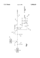
- the drawing is an electrical schematic diagram of a current detector according to the invention, shown in a simplified manner in use with an exemplary ignition system.
- an embodiment of a pulsed current detector according to the present invention is generally indicated with the numeral 10.
- the invention is described herein with respect to a specific embodiment in combination with a specific type of ignition system, this description is intended to be exemplary and should not be construed in a limiting sense.
- Those skilled in the art will readily appreciate that the advantages and benefits of the invention can be realized with many different types of ignition systems and exciter circuit designs including, but not limited to, unidirectional discharge, oscillatory discharge, AC and/or DC charging systems, capacitive and other discharge configurations, periodic and single shot (e.g.
- the invention can be used with ignition systems for many different types of engines, although the description herein is with specific reference to use with a gas turbine engine ignition system particularly suited for use in aerospace applications.
- An exemplary low tension exciter circuit is shown in the drawing and includes a main storage capacitor 12 that is connected to a charging circuit 14.
- the charging circuit 14 can be an AC or DC charger depending on the particular requirements for each application.
- the charging circuit design can be conventional, such as a DC invertor or a continuous AC supply circuit, for example.
- the capacitor 12 is also connected to one side of a switch mechanism 16 which for clarity is shown in a representative manner.
- the switching mechanism can be realized in the form of a spark gap, a gated spark gap, gated solid state switches such as SCR, GTO or MCT devices, either single or cascaded, and so on.
- the ignition system exciter circuit further includes a control circuit 18 that triggers the switching mechanism at the appropriate times.
- control circuit can trigger the switch closed after the capacitor reaches a predetermined charge level, or the circuit can trigger the switch at a predetermined rate based on the desired spark rate.
- Other timing control scenarios can be used, of course, as is well known to those skilled in the art.
- the switching mechanism 16 is also connected to a pulse shaping and output circuit which in this case includes a free wheeling diode 20 and an inductor 22.
- the diode 20 forces the discharge current to be unidirectional, such as is typically required for solid state switching mechanisms.
- the diode can be omitted to produce oscillatory discharge circuits such as are common with spark gap switching devices.
- the inductor 22 is also connected to the igniter (not shown) and functions to limit the initial current surge through the switch to protect, for example, solid state switches.
- Other pulse shaping circuits are well known, such as current and/or voltage step-up circuits and distributed or multiplexed output controls, just to name a few examples.
- the exciter circuit commonly is connected to the igniter by a conductor, such as a high voltage/current cable lead 24 and a return lead (not shown.)
- a conductor such as a high voltage/current cable lead 24 and a return lead (not shown.)
- the capacitor voltage is impressed across the igniter gap. Assuming the voltage exceeds the breakover voltage of the gap, a plasma or similar conductive path jumps the gap and the capacitor quickly discharges with current rising rapidly as represented by the simplified graph 26 in the drawing. Typical discharge times are on the order of tens of microseconds.
- the current discharge pulse can be detected at various points in the ignition circuit.
- the detector circuit is shown in use detecting the current through a conductor that connects the inductor to the switch. Alternatively, however, the detector can be used to sense the current through the high tension lead 24 or the return lead, or even at the igniter itself.
- the detector circuit 10 includes a short conductor or wire 30 that is preferably disposed adjacent to the conductor or other current carrying element at the particular location where pulsed current detection is desired.
- This pick-up wire can be positioned as desired and easily moved as desired to different locations in the ignition circuit.
- the detector 10 can also be realized as a simple add-on feature for the overall system and engine, rather than needing a specific mounting arrangement as is typical with pulse transformers having cores.
- the wire 30 can simply be laid parallel and adjacent to or twisted with (as shown in phantom as at 31 in the drawing) the current carrying element of interest, or attached thereto by any convenient means such as a suitable adhesive.
- the detector 10 simply provides a go/no-go detection function suitable, for example, with a diagnostic system (not shown.) Therefore, precise control of the magnetic coupling is not required thereby allowing the use of an air gap coupling.
- the wire 10 is connected to a peak current detector realized in the form of a rectifying diode 34 and a capacitor 36.
- the current induced in the wire 30 is sufficient to charge the capacitor to a few volts; for example, with a capacitor value of 0.1 ⁇ f and 1 inch wire, a 520 amp discharge can produce a 17 volt output at (V SENSE ).
- the detector 10 produces an output signal 40 (V SENSE ) that can be detected by a diagnostic circuit (not shown) or other suitable means (such as a counter or pulse detector, for example) for detecting the discharge event as represented by the output signal 40.
- the diode 34 blocks discharge of the capacitor 36 due to induced current reversals.
- a large bleed-off resistor 38 may be provided to discharge the capacitor 36 slowly to allow sufficient sampling time for the diagnostic unit, but to fully discharge the capacitor before the next expected discharge event.
Landscapes
- Engineering & Computer Science (AREA)
- Power Engineering (AREA)
- Physics & Mathematics (AREA)
- General Physics & Mathematics (AREA)
- Chemical & Material Sciences (AREA)
- Combustion & Propulsion (AREA)
- Mechanical Engineering (AREA)
- General Engineering & Computer Science (AREA)
- Ignition Installations For Internal Combustion Engines (AREA)
Priority Applications (3)
| Application Number | Priority Date | Filing Date | Title |
|---|---|---|---|
| US08/092,146 US5508618A (en) | 1993-07-15 | 1993-07-15 | Coreless detector for ignition dischage current |
| CA002128035A CA2128035A1 (fr) | 1993-07-15 | 1994-07-14 | Detecteur d'intervalles d'ame creuse pour la detection du courant de decharge d'allumage |
| EP94305210A EP0634574A3 (fr) | 1993-07-15 | 1994-07-15 | Détecteur sans noyau de courant de décharge d'allumage. |
Applications Claiming Priority (1)
| Application Number | Priority Date | Filing Date | Title |
|---|---|---|---|
| US08/092,146 US5508618A (en) | 1993-07-15 | 1993-07-15 | Coreless detector for ignition dischage current |
Publications (1)
| Publication Number | Publication Date |
|---|---|
| US5508618A true US5508618A (en) | 1996-04-16 |
Family
ID=22231855
Family Applications (1)
| Application Number | Title | Priority Date | Filing Date |
|---|---|---|---|
| US08/092,146 Expired - Lifetime US5508618A (en) | 1993-07-15 | 1993-07-15 | Coreless detector for ignition dischage current |
Country Status (3)
| Country | Link |
|---|---|
| US (1) | US5508618A (fr) |
| EP (1) | EP0634574A3 (fr) |
| CA (1) | CA2128035A1 (fr) |
Cited By (11)
| Publication number | Priority date | Publication date | Assignee | Title |
|---|---|---|---|---|
| US6717412B1 (en) | 1999-09-24 | 2004-04-06 | Snap-On Technologies, Inc. | Ignition signal pickup interface box |
| US20050174121A1 (en) * | 2004-02-10 | 2005-08-11 | Ponziani Robert L. | Sensor for detection of spark in igniter in gas turbine engine |
| US20050175491A1 (en) * | 2004-02-10 | 2005-08-11 | Ponziani Robert L. | Integral spark detector in fitting which supports igniter in gas turbine engine |
| US20050172636A1 (en) * | 2004-02-10 | 2005-08-11 | Ponziani Robert L. | Spark igniter for gas turbine engine |
| US20050172637A1 (en) * | 2004-02-10 | 2005-08-11 | Ponziani Robert L. | Detecting spark in igniter of gas turbine engine by detecting signals in grounded RF shielding |
| JP2005226647A (ja) * | 2004-02-10 | 2005-08-25 | General Electric Co <Ge> | ガスタービンエンジンで検出された火花を航空機のパイロットに報知する方法 |
| JP2005240802A (ja) * | 2004-02-10 | 2005-09-08 | General Electric Co <Ge> | ガスタービンエンジンの点火器内で検出された火花信号を増幅するための高温受動増幅器 |
| WO2006078673A1 (fr) * | 2005-01-19 | 2006-07-27 | Seipelt, Christopher | Systeme d'allumage avec indication de bon fonctionnement |
| US20090021249A1 (en) * | 2007-07-19 | 2009-01-22 | Sachin Kumar | Core-less current sensor |
| US20100154382A1 (en) * | 2008-12-23 | 2010-06-24 | Scott Brian Wright | Method and systems for adaptive ignition energy |
| EP3880948A4 (fr) * | 2018-12-21 | 2023-02-22 | Champion Aerospace LLC | Détection de la durée de vie d'un allumeur à étincelle |
Families Citing this family (1)
| Publication number | Priority date | Publication date | Assignee | Title |
|---|---|---|---|---|
| DE102006053935A1 (de) | 2006-11-15 | 2008-05-29 | Siemens Ag | Anordnung und Verfahren zur Ermittlung von Lastströmen in einem Fahrzeug |
Citations (15)
| Publication number | Priority date | Publication date | Assignee | Title |
|---|---|---|---|---|
| FR693911A (fr) * | 1929-08-24 | 1930-11-26 | Dispositif indicateur pour bougies d'allumage | |
| US2645751A (en) * | 1949-07-07 | 1953-07-14 | Hastings Mfg Co | Visual analyzing device for the ignition systems of internal-combustion engines |
| FR1046501A (fr) * | 1951-12-18 | 1953-12-07 | Dispositif électronique de contrôle permanent pour déceler les pannes de bobine d'allumage ou des bougies sur les moteurs à explosion | |
| DE1227731B (de) * | 1963-12-21 | 1966-10-27 | James A Umbarger | Pruefvorrichtung fuer Zuendanlagen von Brennkraftmaschinen |
| US3324393A (en) * | 1963-07-26 | 1967-06-06 | Gen Electric | Magneto-optical electric current sensing arrangement |
| US3793584A (en) * | 1971-03-16 | 1974-02-19 | Tif Instr Inc | Ignition system test instrument and method |
| GB2083308A (en) * | 1980-08-23 | 1982-03-17 | Communic & Electronics Ltd | Voltage generator for testing firing of ignitor |
| US4799005A (en) * | 1983-04-13 | 1989-01-17 | Fernandes Roosevelt A | Electrical power line parameter measurement apparatus and systems, including compact, line-mounted modules |
| DE3735234A1 (de) * | 1987-10-17 | 1989-04-27 | Opel Adam Ag | Zuendanlage fuer einen verbrennungsmotor eines kraftfahrzeuges |
| EP0362014A1 (fr) * | 1988-09-20 | 1990-04-04 | Labo Industrie | Générateur d'allumage haute énergie notamment pour turbine à gaz |
| US5065073A (en) * | 1988-11-15 | 1991-11-12 | Frus John R | Apparatus and method for providing ignition to a turbine engine |
| EP0468253A2 (fr) * | 1990-07-26 | 1992-01-29 | Unison Industries, Inc. | Installation de diagnostic pour système d'allumage de turbine à gaz |
| DE4132285A1 (de) * | 1990-09-27 | 1992-04-09 | Mitsubishi Electric Corp | Zuendkerze fuer eine brennkraftmaschine, die mit einer ionisationsstrom-detektorelektrode ausgestattet ist |
| CA2105042A1 (fr) * | 1992-09-04 | 1994-03-05 | Eychem-Sibal | Generateur d'allumage a haute energie, surtout pour turbine a gaz |
| US5317267A (en) * | 1991-04-12 | 1994-05-31 | Ngk Spark Plug Co., Ltd. | Spark plug voltage probe for use with an internal combustion engine |
Family Cites Families (2)
| Publication number | Priority date | Publication date | Assignee | Title |
|---|---|---|---|---|
| JPS58131573A (ja) * | 1982-01-31 | 1983-08-05 | Matsushita Electric Works Ltd | 電流検出装置 |
| JPH04298685A (ja) * | 1991-03-27 | 1992-10-22 | Ngk Spark Plug Co Ltd | 内燃機関の点火回路の2次電圧センサ |
-
1993
- 1993-07-15 US US08/092,146 patent/US5508618A/en not_active Expired - Lifetime
-
1994
- 1994-07-14 CA CA002128035A patent/CA2128035A1/fr not_active Abandoned
- 1994-07-15 EP EP94305210A patent/EP0634574A3/fr not_active Withdrawn
Patent Citations (16)
| Publication number | Priority date | Publication date | Assignee | Title |
|---|---|---|---|---|
| FR693911A (fr) * | 1929-08-24 | 1930-11-26 | Dispositif indicateur pour bougies d'allumage | |
| US2645751A (en) * | 1949-07-07 | 1953-07-14 | Hastings Mfg Co | Visual analyzing device for the ignition systems of internal-combustion engines |
| FR1046501A (fr) * | 1951-12-18 | 1953-12-07 | Dispositif électronique de contrôle permanent pour déceler les pannes de bobine d'allumage ou des bougies sur les moteurs à explosion | |
| US3324393A (en) * | 1963-07-26 | 1967-06-06 | Gen Electric | Magneto-optical electric current sensing arrangement |
| DE1227731B (de) * | 1963-12-21 | 1966-10-27 | James A Umbarger | Pruefvorrichtung fuer Zuendanlagen von Brennkraftmaschinen |
| US3793584A (en) * | 1971-03-16 | 1974-02-19 | Tif Instr Inc | Ignition system test instrument and method |
| GB2083308A (en) * | 1980-08-23 | 1982-03-17 | Communic & Electronics Ltd | Voltage generator for testing firing of ignitor |
| US4799005A (en) * | 1983-04-13 | 1989-01-17 | Fernandes Roosevelt A | Electrical power line parameter measurement apparatus and systems, including compact, line-mounted modules |
| DE3735234A1 (de) * | 1987-10-17 | 1989-04-27 | Opel Adam Ag | Zuendanlage fuer einen verbrennungsmotor eines kraftfahrzeuges |
| EP0362014A1 (fr) * | 1988-09-20 | 1990-04-04 | Labo Industrie | Générateur d'allumage haute énergie notamment pour turbine à gaz |
| US5065073A (en) * | 1988-11-15 | 1991-11-12 | Frus John R | Apparatus and method for providing ignition to a turbine engine |
| EP0468253A2 (fr) * | 1990-07-26 | 1992-01-29 | Unison Industries, Inc. | Installation de diagnostic pour système d'allumage de turbine à gaz |
| US5155437A (en) * | 1990-07-26 | 1992-10-13 | Unison Industries Limited Partnership | Diagnostic device for gas turbine ignition system |
| DE4132285A1 (de) * | 1990-09-27 | 1992-04-09 | Mitsubishi Electric Corp | Zuendkerze fuer eine brennkraftmaschine, die mit einer ionisationsstrom-detektorelektrode ausgestattet ist |
| US5317267A (en) * | 1991-04-12 | 1994-05-31 | Ngk Spark Plug Co., Ltd. | Spark plug voltage probe for use with an internal combustion engine |
| CA2105042A1 (fr) * | 1992-09-04 | 1994-03-05 | Eychem-Sibal | Generateur d'allumage a haute energie, surtout pour turbine a gaz |
Non-Patent Citations (5)
| Title |
|---|
| Abstract for Japanese Patent No. A 4298685 dated Oct. 22, 1992. * |
| Abstract for Japanese Patent No. A 58131573 dated Aug. 5, 1983. * |
| Abstract for Japanese Patent No. A-4298685 dated Oct. 22, 1992. |
| Abstract for Japanese Patent No. A-58131573 dated Aug. 5, 1983. |
| Copy of European Search Report dated Apr. 3, 1995. * |
Cited By (33)
| Publication number | Priority date | Publication date | Assignee | Title |
|---|---|---|---|---|
| US6717412B1 (en) | 1999-09-24 | 2004-04-06 | Snap-On Technologies, Inc. | Ignition signal pickup interface box |
| US7242195B2 (en) * | 2004-02-10 | 2007-07-10 | General Electric Company | Integral spark detector in fitting which supports igniter in gas turbine engine |
| CN1690388B (zh) * | 2004-02-10 | 2015-11-25 | 通用电气公司 | 在燃气轮机中配合以支持点火器的完整的电火花检测器 |
| US20050172636A1 (en) * | 2004-02-10 | 2005-08-11 | Ponziani Robert L. | Spark igniter for gas turbine engine |
| US20050172637A1 (en) * | 2004-02-10 | 2005-08-11 | Ponziani Robert L. | Detecting spark in igniter of gas turbine engine by detecting signals in grounded RF shielding |
| JP2005226650A (ja) * | 2004-02-10 | 2005-08-25 | General Electric Co <Ge> | 取り付け状態でガスタービンエンジンの点火器を支持する一体型火花検出器 |
| JP2005226988A (ja) * | 2004-02-10 | 2005-08-25 | General Electric Co <Ge> | 接地された高周波シールドにおいて信号を検出することによるガスタービンエンジン点火器の火花検出 |
| US7188466B2 (en) * | 2004-02-10 | 2007-03-13 | General Electric Company | Passive, high-temperature amplifier for amplifying spark signals detected in igniter in gas turbine engine |
| JP2005226647A (ja) * | 2004-02-10 | 2005-08-25 | General Electric Co <Ge> | ガスタービンエンジンで検出された火花を航空機のパイロットに報知する方法 |
| JP2005240802A (ja) * | 2004-02-10 | 2005-09-08 | General Electric Co <Ge> | ガスタービンエンジンの点火器内で検出された火花信号を増幅するための高温受動増幅器 |
| US7015698B2 (en) * | 2004-02-10 | 2006-03-21 | General Electric Company | Sensor for detection of spark in igniter in gas turbine engine |
| US20060137354A1 (en) * | 2004-02-10 | 2006-06-29 | Ponziani Robert L | Passive, high-temperature amplifier for amplifying spark signals detected in igniter in gas turbine engine |
| US20050174121A1 (en) * | 2004-02-10 | 2005-08-11 | Ponziani Robert L. | Sensor for detection of spark in igniter in gas turbine engine |
| US7093422B2 (en) * | 2004-02-10 | 2006-08-22 | General Electric Company | Detecting spark in igniter of gas turbine engine by detecting signals in grounded RF shielding |
| US7093421B2 (en) * | 2004-02-10 | 2006-08-22 | General Electric Company | Spark igniter for gas turbine engine |
| CN1782345B (zh) * | 2004-02-10 | 2011-10-05 | 通用电气公司 | 用于燃气轮机的火花点火器 |
| US20050175491A1 (en) * | 2004-02-10 | 2005-08-11 | Ponziani Robert L. | Integral spark detector in fitting which supports igniter in gas turbine engine |
| JP2005226990A (ja) * | 2004-02-10 | 2005-08-25 | General Electric Co <Ge> | ガスタービンエンジンにおける点火器の火花検出センサ |
| CN100523453C (zh) * | 2004-02-10 | 2009-08-05 | 通用电气公司 | 放大燃气涡轮机点火器的检测火花信号的无源高温放大器 |
| CN100523455C (zh) * | 2004-02-10 | 2009-08-05 | 通用电气公司 | 检测接地射频屏蔽件信号检测燃气涡轮发动机点火器火花 |
| JP4683946B2 (ja) * | 2004-02-10 | 2011-05-18 | ゼネラル・エレクトリック・カンパニイ | 取り付け状態でガスタービンエンジンの点火器を支持する一体型火花検出器 |
| JP4683945B2 (ja) * | 2004-02-10 | 2011-05-18 | ゼネラル・エレクトリック・カンパニイ | ガスタービンエンジンにおける点火器の火花検出センサ |
| JP4681902B2 (ja) * | 2004-02-10 | 2011-05-11 | ゼネラル・エレクトリック・カンパニイ | ガスタービンエンジンで検出された火花を航空機のパイロットに報知する方法 |
| JP4681904B2 (ja) * | 2004-02-10 | 2011-05-11 | ゼネラル・エレクトリック・カンパニイ | 接地された高周波シールドにおいて信号を検出することによるガスタービンエンジン点火器の火花検出 |
| JP4681903B2 (ja) * | 2004-02-10 | 2011-05-11 | ゼネラル・エレクトリック・カンパニイ | ガスタービンエンジンの点火器内で検出された火花信号を増幅するための高温受動増幅器 |
| WO2006078673A1 (fr) * | 2005-01-19 | 2006-07-27 | Seipelt, Christopher | Systeme d'allumage avec indication de bon fonctionnement |
| US7583073B2 (en) | 2007-07-19 | 2009-09-01 | Honeywell International Inc. | Core-less current sensor |
| US20090021249A1 (en) * | 2007-07-19 | 2009-01-22 | Sachin Kumar | Core-less current sensor |
| US20100154382A1 (en) * | 2008-12-23 | 2010-06-24 | Scott Brian Wright | Method and systems for adaptive ignition energy |
| US8266885B2 (en) * | 2008-12-23 | 2012-09-18 | General Electric Company | Method and systems for adaptive ignition energy |
| US8359869B2 (en) | 2008-12-23 | 2013-01-29 | General Electric Company | Method and systems for adaptive ignition energy |
| US11798324B2 (en) | 2018-12-21 | 2023-10-24 | Champion Aerospace Llc | Spark igniter life detection |
| EP3880948A4 (fr) * | 2018-12-21 | 2023-02-22 | Champion Aerospace LLC | Détection de la durée de vie d'un allumeur à étincelle |
Also Published As
| Publication number | Publication date |
|---|---|
| CA2128035A1 (fr) | 1995-01-16 |
| EP0634574A2 (fr) | 1995-01-18 |
| EP0634574A3 (fr) | 1995-05-24 |
Similar Documents
| Publication | Publication Date | Title |
|---|---|---|
| US5508618A (en) | Coreless detector for ignition dischage current | |
| US5758629A (en) | Electronic ignition system for internal combustion engines and method for controlling the system | |
| CA2002121C (fr) | Appareil et methode de lancement d'un moteur a turbine | |
| US5245252A (en) | Apparatus and method for providing ignition to a turbine engine | |
| EP1659670B1 (fr) | Circuit de détection d'un arc électrique | |
| US5599180A (en) | Circuit arrangement for flame detection | |
| EP0516775B1 (fr) | Dispositif de regulation de duree d'etincelle pour un systeme d'allumage a decharge a condensateur | |
| US5572135A (en) | Diagnostic apparatus and methods for ignition circuits | |
| EP0513995B1 (fr) | Détecteur de ratés d'allumage pour un moteur à combustion interne | |
| US4760341A (en) | Method and apparatus for monitoring operation of a spark ignition device in a gas turbine engine | |
| US4404940A (en) | Engine speed limiting circuit | |
| GB2116329A (en) | Apparatus for recognising misfiring in an external ingition internal combustion machine | |
| EP0519588B1 (fr) | Détecteur de ratés d'allumage pour un moteur à combustion interne | |
| JPH0211744B2 (fr) | ||
| US3960128A (en) | Capacitor discharge ignition system | |
| JPS58155279A (ja) | 内燃機関の点火装置回路 | |
| US5970965A (en) | Inductive coil ignition system for an engine | |
| US4186711A (en) | Ignition device with speed limitation for internal combustion engines | |
| US5862033A (en) | Exciter circuit | |
| US4053823A (en) | Ignition arc monitor circuit | |
| US4679540A (en) | Ignition system | |
| US5294888A (en) | Device for detecting misfire of an internal combustion engine by comparing voltage waveforms associated with ignition system | |
| US5115793A (en) | Ignition device for internal combustion engines, particularly for detecting spark failure | |
| US6278278B1 (en) | Measuring and diagnostic device for an ignition system of an internal combustion engine | |
| JP3283605B2 (ja) | イオン電流検出装置 |
Legal Events
| Date | Code | Title | Description |
|---|---|---|---|
| AS | Assignment |
Owner name: SIMMONDS PRECISION ENGINE SYSTEMS, INC. Free format text: ASSIGNMENT OF ASSIGNORS INTEREST;ASSIGNOR:OWENS, DAVID N.;REEL/FRAME:006632/0432 Effective date: 19930714 |
|
| STPP | Information on status: patent application and granting procedure in general |
Free format text: APPLICATION UNDERGOING PREEXAM PROCESSING |
|
| AS | Assignment |
Owner name: UNISON INDUSTRIES LIMITED PARTNERSHIP, FLORIDA Free format text: ASSIGNMENT OF ASSIGNORS INTEREST;ASSIGNOR:SIMMONDS PRECISION ENGINE SYSTEMS, INC.;REEL/FRAME:008723/0868 Effective date: 19970612 |
|
| AS | Assignment |
Owner name: UNISON INDUSTRIES, INC., FLORIDA Free format text: ASSIGNMENT OF ASSIGNORS INTEREST;ASSIGNOR:UNISON INDUSTRIES LIMITED PARTNERSHIP;REEL/FRAME:009556/0359 Effective date: 19981029 |
|
| AS | Assignment |
Owner name: BANK OF AMERICA NATIONAL TRUST & SAVINGS ASSOCIATI Free format text: SECURITY INTEREST;ASSIGNOR:UNISON INDUSTRIES, INC.;REEL/FRAME:010321/0645 Effective date: 19980901 |
|
| REMI | Maintenance fee reminder mailed | ||
| FPAY | Fee payment |
Year of fee payment: 4 |
|
| SULP | Surcharge for late payment | ||
| AS | Assignment |
Owner name: UNISON INDUSTRIES, INC., FLORIDA Free format text: SECURITY AGREEMENT RELEASE;ASSIGNOR:BANK OF AMERICA, N.A.;REEL/FRAME:012831/0962 Effective date: 20020417 |
|
| FPAY | Fee payment |
Year of fee payment: 8 |
|
| AS | Assignment |
Owner name: UNISON INDUSTRIES, LLC., FLORIDA Free format text: CHANGE OF NAME;ASSIGNOR:UNISON INDUSTRIES, INC.;REEL/FRAME:014718/0429 Effective date: 20021223 |
|
| FPAY | Fee payment |
Year of fee payment: 12 |