US5447212A - Measurement and reduction of bunching in elevator dispatching with multiple term objection function - Google Patents
Measurement and reduction of bunching in elevator dispatching with multiple term objection function Download PDFInfo
- Publication number
- US5447212A US5447212A US08/279,666 US27966694A US5447212A US 5447212 A US5447212 A US 5447212A US 27966694 A US27966694 A US 27966694A US 5447212 A US5447212 A US 5447212A
- Authority
- US
- United States
- Prior art keywords
- car
- cars
- hall call
- bunching
- floor
- Prior art date
- Legal status (The legal status is an assumption and is not a legal conclusion. Google has not performed a legal analysis and makes no representation as to the accuracy of the status listed.)
- Expired - Lifetime
Links
Images


Classifications
-
- B—PERFORMING OPERATIONS; TRANSPORTING
- B66—HOISTING; LIFTING; HAULING
- B66B—ELEVATORS; ESCALATORS OR MOVING WALKWAYS
- B66B1/00—Control systems of elevators in general
- B66B1/24—Control systems with regulation, i.e. with retroactive action, for influencing travelling speed, acceleration, or deceleration
- B66B1/2408—Control systems with regulation, i.e. with retroactive action, for influencing travelling speed, acceleration, or deceleration where the allocation of a call to an elevator car is of importance, i.e. by means of a supervisory or group controller
- B66B1/2458—For elevator systems with multiple shafts and a single car per shaft
-
- B—PERFORMING OPERATIONS; TRANSPORTING
- B66—HOISTING; LIFTING; HAULING
- B66B—ELEVATORS; ESCALATORS OR MOVING WALKWAYS
- B66B2201/00—Aspects of control systems of elevators
- B66B2201/10—Details with respect to the type of call input
- B66B2201/102—Up or down call input
-
- B—PERFORMING OPERATIONS; TRANSPORTING
- B66—HOISTING; LIFTING; HAULING
- B66B—ELEVATORS; ESCALATORS OR MOVING WALKWAYS
- B66B2201/00—Aspects of control systems of elevators
- B66B2201/20—Details of the evaluation method for the allocation of a call to an elevator car
- B66B2201/211—Waiting time, i.e. response time
-
- B—PERFORMING OPERATIONS; TRANSPORTING
- B66—HOISTING; LIFTING; HAULING
- B66B—ELEVATORS; ESCALATORS OR MOVING WALKWAYS
- B66B2201/00—Aspects of control systems of elevators
- B66B2201/20—Details of the evaluation method for the allocation of a call to an elevator car
- B66B2201/226—Taking into account the distribution of elevator cars within the elevator system, e.g. to prevent clustering of elevator cars
-
- B—PERFORMING OPERATIONS; TRANSPORTING
- B66—HOISTING; LIFTING; HAULING
- B66B—ELEVATORS; ESCALATORS OR MOVING WALKWAYS
- B66B2201/00—Aspects of control systems of elevators
- B66B2201/20—Details of the evaluation method for the allocation of a call to an elevator car
- B66B2201/233—Periodic re-allocation of call inputs
-
- B—PERFORMING OPERATIONS; TRANSPORTING
- B66—HOISTING; LIFTING; HAULING
- B66B—ELEVATORS; ESCALATORS OR MOVING WALKWAYS
- B66B2201/00—Aspects of control systems of elevators
- B66B2201/30—Details of the elevator system configuration
- B66B2201/301—Shafts divided into zones
-
- B—PERFORMING OPERATIONS; TRANSPORTING
- B66—HOISTING; LIFTING; HAULING
- B66B—ELEVATORS; ESCALATORS OR MOVING WALKWAYS
- B66B2201/00—Aspects of control systems of elevators
- B66B2201/30—Details of the elevator system configuration
- B66B2201/303—Express or shuttle elevators
Definitions
- the present invention relates to bunching of elevators.
- Bunching is defined loosely to mean that certain cars are "close together”.
- the absence of bunching means that the cars are evenly distributed amongst the floors.
- Bunching is not always undesirable, as when several cars converge to a convention floor to move a large number of people. As a rule, however, bunching is undesirable.
- a system in which the cars are evenly distributed amongst the floors will result in a minimum average waiting time for the randomly arriving passenger.
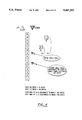
- FIG. 1 shows both Cars A and B traveling down in the top part of a 15-story building. Also, Cars C and D are reasonably close to one another.
- a wait-so-far time when the hall call was registered to the present time, is shown for each hall call.
- the waiting time is the time from when a passenger presses a hall call button until the elevator arrives. Intuitively, a longer than desired waiting time might occur if a passenger would register a down hall call at Floor 15.
- the maximum waiting times could be reduced if the cars were more evenly distributed: Car A might be positioned at Floor 7-DOWN, and Car C might be positioned at floor 8-UP.
- FIG. 1 shows that this repositioning of the cars is impossible because of the hall call and car call assignments.
- the impossibility of the proposed repositioning of the cars underscores the difficult nature of solving the bunching problem.
- Objectives in the present invention include assigning an elevator car to a hall call such that elevators in an elevator group tend to be equally spaced apart as they service hall calls and car calls and therefore bunching is avoided.
- the position of each car is predicted over a given period of time by estimating when it will arrive and leave each of its committed stops over that period for a given set of hall call/car call assignments.
- a bunching measure is calculated and a car to hall call assignment is made in response to the bunching measure.
- Advantages of the present invention include reduced registration time, as compared with the prior art dispatching schemes. As a consequence of avoiding bunching, cars tend to be evenly distributed throughout the building, and therefore, better positioned for servicing hall calls and car calls.
- FIG. 1 is a snapshot at a specific moment in time of hall calls and car calls mapped to floors and cars.
- FIG. 2 maps floors against the location of a car B and car calls and hall calls for assignment for car B.
- FIG. 3 is a mapping of floors against the location of cars B, C and car calls associated with those elevators and a hall call associated with car B.
- FIG. 4 is a map of floors against registered hall calls, and the location of cars B, C.
- FIG. 5 is a circular model of the floors in a building, and the up or down directions, for an equal distribution of elevator cars.
- FIG. 6 is a circular model as in FIG. 5, but for an unequal distribution of cars and an associated snapshot without hall calls or car calls shown.
- FIG. 7 is a chart of estimated arrival and departure times at committed stops for elevator cars.
- FIG. 8 is a chart of estimated car positions at five second intervals.
- FIG. 9 is a snapshot at a specific moment in time of hall calls and car calls mapped to floors and cars.
- FIG. 10a is a chart of the estimated time of arrival and departure at the committed stops of four elevators assuming that a down hall call on floor 11 is assigned to an elevator A of the four elevators, A-D.
- FIG. 10b is an estimation of car positions at five second intervals assuming assignments of the down hall on floor 11 to car A.
- FIG. 11a is a chart of the estimated time of arrival and departure at the committed stops of four elevators but assuming that the down hall call on floor 11 is assigned to car B.
- FIG. 11b is an estimation of car positions at five second intervals assuming that the down hall call at floor 11 is assigned to car B.
- FIG. 12 is a snapshot at a specific moment in time of hall calls and car calls mapped to floors and cars in a building having an express zone.
- FIG. 13 is a circular model of the floors in the building, and the up or down directions, for a building having an express zone and an unequal distribution of cars.
- FIG. 14a is a chart of the estimated time of arrival and departure of elevator cars at their committed stops assuming that a down hall call on floor 31 is assigned to a car A of the four cars, A-D.
- FIG. 14b is an estimation of the car positions of the four cars A-D at five second intervals assuming that a down hall call on floor 31 is assigned to a car A of the four cars, A-D.
- FIG. 17 is a master flowchart for illustrating the method of the present invention.
- FIG. 18 is a flow chart of a hall call assignment algorithm.
- Dispatching cars to hall calls can be done with or without instantaneous car assignment (ICA).
- ICA instantaneous car assignment
- ICA informs the user at the instant of first assignment (or shortly thereafter) as to which car will service his/her hall call. The benefit is that the user can be walking toward that particular car, of the bank of cars, which is going to serve him and be positioned and ready to enter that car when it arrives.
- Assigning a hall call to a car in response to an objective function employing a bunching measure consists of two parts. First, for a new hall call, a car is assigned to the call by choosing the car which provides the minimum value of the objective (meaning goal) function:
- the RSR algorithm uses an objective function.
- the RSR algorithm and various modifications of it can be said to include various terms, depending on the RSR algorithm employed.
- the basic component of the RSR quantity is an estimate of the number of seconds an elevator would require to reach a hall call.
- FIG. 3 maps floors in a building against car calls for cars B and C and a hall call assigned to car B.
- FIG. 3 illustrates the remaining response time concept after a hall call has already been waiting an exemplary time of 20 seconds.
- a car B is traveling in the downward direction to service two car calls before servicing a hall call assigned to car B where the passenger has already been waiting for 20 seconds.
- a car C is moving in the upward direction to service a car call at a floor above the location of the hall call. The question arises as to whether the hall call should remain assigned to car B or be reassigned to car C.
- the predicted registration time metric is included in the objective function as the absolute value of the difference between the predicted registration time and the term, T 1 , of 20 seconds. If the predicted registration time is either very short or very long, then the term, T 1 , penalizes a car. This reflects the philosophy in some markets that a passenger is willing to wait approximately 20 seconds without any level of discomfort. Of course, this penalty term is variable and need not be 20 seconds. Therefore, a car that could reach the hall call in a very short time (for example, five seconds) might better proceed to answer other more urgent elevator system demands.
- the present invention proposes to address these long calls by penalizing the car for an assignment only when that assignment will cause the longest waiting call (of all hall calls presently waiting) to wait longer than a term, T 2 , 60 seconds. It is thought that a call that has already waited 60 seconds has a potential to cross the 90 seconds threshold and therefore should be given special consideration.
- the penalty term is variable and need not be 60 seconds.
- the term is squared in the objective function to reflect the passengers growing irritation which is felt to be nonlinear and increasing as the waiting time increases beyond 60 seconds.
- maxPRT like PRT, need not be squared but could be the argument for any other function to model passenger irritation.
- the Dirac Delta operator ensures that the third term is zero where maxPRT is not longer than 60 seconds.
- This metric is used currently in the objective function in order to allow the building owner to revert to the prior art RSR dispatching methodology.
- the value of the RSR term selected depends upon which form of RSR is desired, as it has many modifications.
- the basic component of the RSR quantity is the estimated amount of time for a car to reach the hall call whose assignment is being determined.
- the value selected, however, for the RSR value may be any of those shown in U.S. Pat. No. 5,146,053 issued to Powell et al entitled Elevator Dispatching Based on Remaining Response Time; U.S. Pat. No. 4,363,381 issued to Bittar, entitled Relative System Response Elevator Call Assignments; U.S. Pat. No. 4,815,568 to Bittar entitled Weighted Relative System Elevator Car Assignment System with Variable Bonuses and Penalties; U.S. Pat. No.
- a building's floors are represented on a circle (FIG. 5), and the cars travel in a clockwise direction.
- the cars are perfectly distributed if they are in positions as shown. Up and down are indicated by "U” and "D" after the floor number.
- the arc distance between each car is the same--seven floors.
- Cars are proximate if a) there is no car between them commanded to travel in the same direction or parked between them and b) there is no car between either of them and a terminal. For example, A and B are proximate cars but A and C are not.
- FIG. 5 represents the ideal distribution of cars. In fact, it can be shown mathematically that this sum of squares is minimized when all of the distances are seven. This mathematical result generalizes for N cars serving F floors. The sum of squares is minimized when the distances are all equal to 2(F-1)/N.
- FIG. 6 shows the cars in positions that they were in FIG. 1.
- the measure of bunching is ##EQU2##
- the method of squaring distances provides a quantitative measure of bunching for a group of elevators at a single instant in time. Although this is useful, a more important issue is the likelihood for the cars to become bunched in the next 30 seconds. Say that a new hall call has been registered, and the dispatcher must assign a car to it. The following question is crucial:
- FIG. 7 shows the results of such a process. Assume first that no new hall calls or car calls are entered. Then, Car A will arrive at floor 10-DOWN at time 4.0 seconds from now and will leave Floor 10-DOWN at time 10.0, will arrive at Floor 8-DOWN at time 14.0, etc.
- the HC indicates when a hall call is canceled. The arrow indicates the direction a car is heading in.
- the second phase of the process is to take the position data of FIG. 7 and interpolate to obtain car positions at regular intervals.
- FIG. 8 shows the estimated car positions at five second intervals. Then, for each five second epoch, a measure of bunching can be calculated by squaring the distances. Finally, an average bunching measure (ABM) over the next 30 seconds is obtained.
- ABSM average bunching measure
- the method of estimating future car positions can be done any number of ways. Although the success of the present invention will depend on the accuracy of the estimates, the method of estimation is NOT part of the present invention. For the examples cited, a simplification was made where a car would require two seconds per floor to travel and would remain at each stopped floor for six seconds. In practice, known floor-to-floor travel times would be used, and a better estimate of stopped time would be obtained from load-weight and other relevant information.
- FIG. 9 shows a new hall call registered at floor 11 but not yet assigned. As in FIG. 1 the wait-time-so-far for each hall call is shown also.
- FIGS. 10A and 10B correspond to FIGS. 4 and 5 except in FIGS. 10A and 10B the hall call at floor 11 is assumed to be assigned to car A for the purposes of determining what bunching will result.
- FIGS. 11A and 11B are similar to FIGS. 10A and 10B except the hall call at floor 11 is assumed to be assigned to car B. Because the average bunching measure is lower for the assignment of the hall call to car B, considering no other factors, the assignment should be made to car B rather than car A.
- FIGS. 10A, 10B, 11A, 11B are offered to show that the average bunching measure depends upon which car the hall call is assigned to, car B, for example, rather than car A.
- FIGS. 12 and 13 show a bank of elevators in a building having an express zone wherein cars travel nonstop between the lobby and the 30th floor.
- the model in FIG. 13 divides the express zone in three segments.
- a car traveling upwards from the lobby is said to have completed each of the first two segments of its travel as it passes the two artificial "floors" Lower Express UP (Lower EX-U) and Upper Express UP (Upper EX-U).
- Lower Express UP Lower EX-U
- Upper Express UP Upper EX-U
- a car traveling in the express zone is assumed to have a position at the nearest artificial floor.
- the determination of the number of segments to use in modeling the express zone is not exactly specified in this invention.
- the general intent is to treat local floors (those floors above an express zone) differently from floors in the express zone.
- the express zone travel is approximately 24 seconds. It has been assumed earlier in this application that the time required for a car to depart a particular floor, travel to an adjacent floor, and spend time at the adjacent floor is 8 seconds (2 seconds for travel and 6 seconds for stopping). For this case, the express zone travel is approximately equivalent to three local floors. Hence, three segments in the express zone.
- FIG. 14a shows the results of such a process. Assume first that no new hall calls or car calls are entered. Then, Car A will arrive at floor 32-DOWN at time 4.0 seconds from now and will leave Floor 32-DOWN at time 10.0 seconds, will arrive at Floor 31-DOWN at time 12.0 seconds, etc.
- the HC indicates when a hall call is canceled. Arrows indicate direction. Stops at a floor without the HC designation indicate car call stops.
- the second phase of the process of measuring bunching is to take the position data of FIG. 14a and interpolate to obtain car position at regular intervals.
- FIG. 14b shows the estimated car position at five second intervals. Then, for each five second interval, a measure of bunching can be calculated by squaring the distances. Finally, an average bunching measure over the next 30 seconds is obtained.
- FIG. 15 is a flowchart for calculating a bunching measure at a given moment in time.
- FIG. 16 is a flowchart for calculating the average bunching measure predicted over the next 30 seconds.
- FIG. 15 The flowchart in FIG. 15 is executed each time a hall call assignment must be made.
- a car position vector is created within a computer in the elevator dispatcher.
- the car position vector is functionally the same as the circular model of FIGS. 5, 6, and 13; the linear model of FIG. 15 looks different from the circular one, but the former is merely the model of the latter on a straight line.
- the linear model is useful in calculating the bunching measure whereas the circular model is useful for understanding why a bunching measure that is a function of the distance between proximate cars and is effective in minimizing bunching.
- Adjacent cars on the linear or circular model are proximate cars. For example, A and B are proximate cars but A and C are not.
- the car position vector includes (2F-2) elements where F is the number of floors from one terminal of an elevator run to the other.
- Each entry in the car position vector has a floor value and a direction value, either up or down, except for the floors at either terminal.
- the floor at the bottom terminal can only have an up direction value and the floor at the top terminal can only have a down direction value. As shown, these floors are 1 and F respectively.
- Each element of the car position vector represents a possible position for a car in the building (for example, 2-UP is an element, 3-UP is an element, . . . , 2-DOWN).
- each element in the car position vector corresponds to a stopping position (that is, a floor--direction pair).
- a stopping position that is, a floor--direction pair.
- one element is included for each 8 seconds of travel time for an elevator car travelling within the express zone less one.
- Floors which are not available to be serviced are treated like express zones except when there is an isolated floor interspersed among floors available for service, in which case these floors are not included as elements in the car position vector.
- the location of each car on the car position vector is determined.
- Algorithms for learning the position of an elevator car are well known as are algorithms for determining which direction an elevator car is moving (or will be moving if the car is stopped). Hence, this step includes merely collecting this data--floor position and direction of movement--for each car.
- the distance between proximate cars is determined.
- N is the number of cars available to assign to a hall call.
- the value i can have a value, therefore, between 1 and N.
- the position index of each car is shown on the car position vector in FIG. 15.
- I N is the last car.
- car C is the first car and car B is the last car.
- the position indices associated with these cars are I 1 and I 4 , respectively, for the four car group shown.
- FIG. 16 is a flowchart for providing the average bunching measure predicted over the next 30 seconds. After start, the location of each car at five second intervals over the next 30 second period is estimated. Next, the bunching measure at each five second interval is calculated for the next 30 seconds. This entails calling and executing the routine in FIG. 15 for each five second interval. Alternative to these first two steps of FIG. 16 is calculating the bunching measure for each five second interval in the same manner shown and described with respect to FIGS. 5-14b. That is, the time of arrival and departure at all committed stops in the next 30 seconds is estimated for each car, and then position data associated with these arrival times and departure times is interpolated to yield car positions at regular five second intervals. Next, the bunching measures for each of the five second intervals are summed and divided by the number of five second intervals in the 30 second period for providing an average bunching measure for that 30 second period. This is then used in the multi-term objective function described below.
- FIG. 17 is a master flow chart for implementing the method of the present invention. After a start, a hall call at a floor N in a given direction is registered. Then, an elevator dispatcher determines if the hall call was previously assigned to a car and records the car of the assignment. Next, the remaining response time is calculated for each car in the bank and the lowest remaining response time and the car associated with it is determined.
- a series of tests is now executed to determine if a hall call assignment algorithm FIG. 18 for reassigning the call should be executed.
- the routines of FIG. 18 incorporate the basic concept of instantaneous car assignment in that the call is not reassigned unless there are strong incentives for doing so; even then, no more than one reassignment is allowed.
- the first test asks "Is this a new hall call?". If so, completion of the routine of FIG. 17 waits for execution of the hall call assignment algorithm illustrated in FIG. 18. If not, the next three tests may be executed for determining whether the previously assigned call should be reassigned. In test two, if the remaining response time of the assigned elevator is greater than the lowest remaining response time plus 40 seconds, execution of the routine at FIG.
- FIG. 18 illustrates the hall call assignment algorithm.
- the remaining response time already computed for the current set of assignments of hall calls to cars is read and used for computing the predicted registration time (PRT) for all hall calls, by adding the wait-time-so-far for each call to the associated remaining response time.
- PRT predicted registration time
- a car index icar is set to zero. The index is incremented by one for each car in the bank, and a multi-term objective function is computed for that car, until all cars have been considered.
- the car with the lowest objective function is determined and given a label KAR.
- a series of tests is then executed for determining whether there should be a reassignment. These three tests are similar to the four tests of FIG. 17 insofar as their execution infrequently results in reassignment of a call out of deference to instantaneous car assignment.
- the hall call is assigned. If the hall call is not a new call (test two) and the call has already been switched once from the car of first assignment, then the hall call is not reassigned. If the call is not a new one, then the predicted registration time (PRT) of the assigned car is compared with the predicted registration time (PRT) of the car, "KAR", with the lowest objective function.
- FIG. 19 illustrates calculation of the multi-term objective function.
- the wait-time-so-far for each hall call is stored and mapped against the direction of that hall call.
- the car for which the objective function is being calculated is assumed to be assigned to the call being considered for reassignment in the master flow chart routine.
- the remaining response time (RRT), predicted registration time (PRT), maximum predicted registration time (maxPRT), the RSR value, and average bunching measure (ABM) are calculated.
- the values for the five terms of the multi-term objective function are now calculated and summed for producing the multi-term objective function for use in the hall call assignment algorithm.
- FIG. 20 is a graph of the objective function of the cars in a bank; the car with the minimum value of the objective function (car B) is assigned to a hall call.
Landscapes
- Engineering & Computer Science (AREA)
- Automation & Control Theory (AREA)
- Elevator Control (AREA)
Priority Applications (1)
| Application Number | Priority Date | Filing Date | Title |
|---|---|---|---|
| US08/279,666 US5447212A (en) | 1993-05-05 | 1994-07-25 | Measurement and reduction of bunching in elevator dispatching with multiple term objection function |
Applications Claiming Priority (2)
| Application Number | Priority Date | Filing Date | Title |
|---|---|---|---|
| US5891793A | 1993-05-05 | 1993-05-05 | |
| US08/279,666 US5447212A (en) | 1993-05-05 | 1994-07-25 | Measurement and reduction of bunching in elevator dispatching with multiple term objection function |
Related Parent Applications (1)
| Application Number | Title | Priority Date | Filing Date |
|---|---|---|---|
| US5891793A Continuation | 1993-05-05 | 1993-05-05 |
Publications (1)
| Publication Number | Publication Date |
|---|---|
| US5447212A true US5447212A (en) | 1995-09-05 |
Family
ID=22019716
Family Applications (1)
| Application Number | Title | Priority Date | Filing Date |
|---|---|---|---|
| US08/279,666 Expired - Lifetime US5447212A (en) | 1993-05-05 | 1994-07-25 | Measurement and reduction of bunching in elevator dispatching with multiple term objection function |
Country Status (5)
| Country | Link |
|---|---|
| US (1) | US5447212A (fr) |
| EP (1) | EP0623545B1 (fr) |
| JP (1) | JP3461565B2 (fr) |
| DE (1) | DE69405907T2 (fr) |
| HK (1) | HK1004913A1 (fr) |
Cited By (5)
| Publication number | Priority date | Publication date | Assignee | Title |
|---|---|---|---|---|
| US5865274A (en) * | 1995-10-24 | 1999-02-02 | Kabushiki Kaisha Toshiba | Elevator group management control apparatus and elevator group management control method |
| US5904227A (en) * | 1997-12-30 | 1999-05-18 | Otis Elevator Company | Method for continuously adjusting the architecture of a neural network used in elevator dispatching |
| US20060237264A1 (en) * | 2003-05-19 | 2006-10-26 | Christy Theresa M | Elevator car separation based on response time |
| CN113003328A (zh) * | 2019-12-20 | 2021-06-22 | 奥的斯电梯公司 | 对往返电梯组的控制 |
| CN115215169A (zh) * | 2022-07-12 | 2022-10-21 | 日立楼宇技术(广州)有限公司 | 电梯群控方法、装置、电梯群控设备和存储介质 |
Families Citing this family (7)
| Publication number | Priority date | Publication date | Assignee | Title |
|---|---|---|---|---|
| WO2005092762A1 (fr) * | 2004-03-26 | 2005-10-06 | Mitsubishi Denki Kabushiki Kaisha | Systeme de commande d'un groupe d'ascenseurs |
| JP4567553B2 (ja) * | 2005-08-31 | 2010-10-20 | 株式会社日立製作所 | エレベータの群管理システム及びその制御方法 |
| JP4782519B2 (ja) * | 2005-09-20 | 2011-09-28 | 株式会社日立製作所 | エレベータの群管理システム |
| JP4763403B2 (ja) * | 2005-09-27 | 2011-08-31 | 株式会社日立製作所 | エレベータの群管理システム及びその制御方法 |
| JP4573741B2 (ja) * | 2005-09-27 | 2010-11-04 | 株式会社日立製作所 | エレベータの群管理システム及びその制御方法 |
| WO2010055563A1 (fr) * | 2008-11-13 | 2010-05-20 | 三菱電機株式会社 | Système de commande de groupe d'ascenseur |
| DE102018213573B4 (de) * | 2018-08-13 | 2020-03-19 | Thyssenkrupp Ag | Aufzuganlage sowie Verfahren zum Betreiben einer Aufzuganlage |
Citations (16)
| Publication number | Priority date | Publication date | Assignee | Title |
|---|---|---|---|---|
| US3837436A (en) * | 1970-07-01 | 1974-09-24 | Hitachi Ltd | Elevator control system |
| US4363381A (en) * | 1979-12-03 | 1982-12-14 | Otis Elevator Company | Relative system response elevator call assignments |
| US4760896A (en) * | 1986-10-01 | 1988-08-02 | Kabushiki Kaisha Toshiba | Apparatus for performing group control on elevators |
| US4782921A (en) * | 1988-03-16 | 1988-11-08 | Westinghouse Electric Corp. | Coincident call optimization in an elevator dispatching system |
| US4790412A (en) * | 1988-03-16 | 1988-12-13 | Westinghouse Electric Corp. | Anti-bunching method for dispatching elevator cars |
| US4815568A (en) * | 1988-05-11 | 1989-03-28 | Otis Elevator Company | Weighted relative system response elevator car assignment system with variable bonuses and penalties |
| US4838384A (en) * | 1988-06-21 | 1989-06-13 | Otis Elevator Company | Queue based elevator dispatching system using peak period traffic prediction |
| US4947965A (en) * | 1988-02-03 | 1990-08-14 | Hitachi, Ltd. | Group-control method and apparatus for an elevator system with plural cages |
| US4982817A (en) * | 1988-10-19 | 1991-01-08 | Mitsubishi Denki Kabushiki Kaisha | Group supervision apparatus for elevator system |
| JPH0351271A (ja) * | 1989-07-17 | 1991-03-05 | Toshiba Corp | エレベータの群管理制御方法 |
| US5022497A (en) * | 1988-06-21 | 1991-06-11 | Otis Elevator Company | "Artificial intelligence" based crowd sensing system for elevator car assignment |
| US5024295A (en) * | 1988-06-21 | 1991-06-18 | Otis Elevator Company | Relative system response elevator dispatcher system using artificial intelligence to vary bonuses and penalties |
| US5035302A (en) * | 1989-03-03 | 1991-07-30 | Otis Elevator Company | "Artificial Intelligence" based learning system predicting "Peak-Period" times for elevator dispatching |
| US5146053A (en) * | 1991-02-28 | 1992-09-08 | Otis Elevator Company | Elevator dispatching based on remaining response time |
| US5168136A (en) * | 1991-10-15 | 1992-12-01 | Otis Elevator Company | Learning methodology for improving traffic prediction accuracy of elevator systems using "artificial intelligence" |
| US5202540A (en) * | 1986-04-03 | 1993-04-13 | Otis Elevator Company | Two-way ring communication system for elevator group control |
-
1994
- 1994-05-05 DE DE69405907T patent/DE69405907T2/de not_active Expired - Fee Related
- 1994-05-05 EP EP94303252A patent/EP0623545B1/fr not_active Expired - Lifetime
- 1994-05-06 JP JP09447694A patent/JP3461565B2/ja not_active Expired - Fee Related
- 1994-07-25 US US08/279,666 patent/US5447212A/en not_active Expired - Lifetime
-
1998
- 1998-01-22 HK HK98100573A patent/HK1004913A1/xx not_active IP Right Cessation
Patent Citations (16)
| Publication number | Priority date | Publication date | Assignee | Title |
|---|---|---|---|---|
| US3837436A (en) * | 1970-07-01 | 1974-09-24 | Hitachi Ltd | Elevator control system |
| US4363381A (en) * | 1979-12-03 | 1982-12-14 | Otis Elevator Company | Relative system response elevator call assignments |
| US5202540A (en) * | 1986-04-03 | 1993-04-13 | Otis Elevator Company | Two-way ring communication system for elevator group control |
| US4760896A (en) * | 1986-10-01 | 1988-08-02 | Kabushiki Kaisha Toshiba | Apparatus for performing group control on elevators |
| US4947965A (en) * | 1988-02-03 | 1990-08-14 | Hitachi, Ltd. | Group-control method and apparatus for an elevator system with plural cages |
| US4782921A (en) * | 1988-03-16 | 1988-11-08 | Westinghouse Electric Corp. | Coincident call optimization in an elevator dispatching system |
| US4790412A (en) * | 1988-03-16 | 1988-12-13 | Westinghouse Electric Corp. | Anti-bunching method for dispatching elevator cars |
| US4815568A (en) * | 1988-05-11 | 1989-03-28 | Otis Elevator Company | Weighted relative system response elevator car assignment system with variable bonuses and penalties |
| US5024295A (en) * | 1988-06-21 | 1991-06-18 | Otis Elevator Company | Relative system response elevator dispatcher system using artificial intelligence to vary bonuses and penalties |
| US4838384A (en) * | 1988-06-21 | 1989-06-13 | Otis Elevator Company | Queue based elevator dispatching system using peak period traffic prediction |
| US5022497A (en) * | 1988-06-21 | 1991-06-11 | Otis Elevator Company | "Artificial intelligence" based crowd sensing system for elevator car assignment |
| US4982817A (en) * | 1988-10-19 | 1991-01-08 | Mitsubishi Denki Kabushiki Kaisha | Group supervision apparatus for elevator system |
| US5035302A (en) * | 1989-03-03 | 1991-07-30 | Otis Elevator Company | "Artificial Intelligence" based learning system predicting "Peak-Period" times for elevator dispatching |
| JPH0351271A (ja) * | 1989-07-17 | 1991-03-05 | Toshiba Corp | エレベータの群管理制御方法 |
| US5146053A (en) * | 1991-02-28 | 1992-09-08 | Otis Elevator Company | Elevator dispatching based on remaining response time |
| US5168136A (en) * | 1991-10-15 | 1992-12-01 | Otis Elevator Company | Learning methodology for improving traffic prediction accuracy of elevator systems using "artificial intelligence" |
Cited By (6)
| Publication number | Priority date | Publication date | Assignee | Title |
|---|---|---|---|---|
| US5865274A (en) * | 1995-10-24 | 1999-02-02 | Kabushiki Kaisha Toshiba | Elevator group management control apparatus and elevator group management control method |
| US5904227A (en) * | 1997-12-30 | 1999-05-18 | Otis Elevator Company | Method for continuously adjusting the architecture of a neural network used in elevator dispatching |
| US20060237264A1 (en) * | 2003-05-19 | 2006-10-26 | Christy Theresa M | Elevator car separation based on response time |
| US7152714B2 (en) * | 2003-05-19 | 2006-12-26 | Otis Elevator Company | Elevator car separation based on response time |
| CN113003328A (zh) * | 2019-12-20 | 2021-06-22 | 奥的斯电梯公司 | 对往返电梯组的控制 |
| CN115215169A (zh) * | 2022-07-12 | 2022-10-21 | 日立楼宇技术(广州)有限公司 | 电梯群控方法、装置、电梯群控设备和存储介质 |
Also Published As
| Publication number | Publication date |
|---|---|
| DE69405907T2 (de) | 1998-03-19 |
| EP0623545B1 (fr) | 1997-10-01 |
| EP0623545A1 (fr) | 1994-11-09 |
| HK1004913A1 (en) | 1998-12-11 |
| JP3461565B2 (ja) | 2003-10-27 |
| JPH06340379A (ja) | 1994-12-13 |
| DE69405907D1 (de) | 1997-11-06 |
Similar Documents
| Publication | Publication Date | Title |
|---|---|---|
| US5024295A (en) | Relative system response elevator dispatcher system using artificial intelligence to vary bonuses and penalties | |
| US4838384A (en) | Queue based elevator dispatching system using peak period traffic prediction | |
| US5447212A (en) | Measurement and reduction of bunching in elevator dispatching with multiple term objection function | |
| EP0444969B1 (fr) | Système d'apprentissage utilisant l'intelligence artificielle pour la prédiction des heures de pointe pour la distribution d'appels d'ascenseur | |
| EP0348151B1 (fr) | Système optimisé de répartition d'ascenseur pour pointe ascendente de trafic | |
| JP3042904B2 (ja) | エレベータ配送システム | |
| JP4602086B2 (ja) | エレベータシステムを制御する方法およびエレベータシステムのためのコントローラ | |
| KR920011080B1 (ko) | 엘리베이터의 군(群)관리장치 | |
| US5239141A (en) | Group management control method and apparatus for an elevator system | |
| KR20190140829A (ko) | 엘리베이터의 군관리 제어 시스템 | |
| JPH04317966A (ja) | 残り応答時間に基づくエレベータ運行方法 | |
| JP2004520251A (ja) | エレベータ群管理方法 | |
| US4792019A (en) | Contiguous floor channeling with up hall call elevator dispatching | |
| EP0452225A2 (fr) | Canalisation dynamique de la distribution d'appels d'ascenseur pour les heures de pointe du trafic montant | |
| JPH06271213A (ja) | エレベーターの群管理制御装置 | |
| JP2000501058A (ja) | シングルソーストラフィック条件のための動的スケジューリングエレベータ配送装置 | |
| JP2001310876A (ja) | ダブルデッキエレベータシステムの制御装置および制御方法 | |
| US5388668A (en) | Elevator dispatching with multiple term objective function and instantaneous elevator assignment | |
| JPH07117941A (ja) | エレベータの群管理制御装置 | |
| EP0623546B1 (fr) | Répartiteur pour ascenseur avec fonction d'objectivité à terme multiple et assignation instantanée d'un ascenseur | |
| JPH11209010A (ja) | エレベータ群管理装置及び方法 | |
| Basagoiti et al. | Passenger flow pattern learning based on trip counting in lift systems combined with real-time information | |
| JP3714343B2 (ja) | エレベータ群管理簡易シミュレータならびにエレベータ群管理装置 | |
| JPH055747B2 (fr) | ||
| JPH11349239A (ja) | エレベーターの群管理運転装置 |
Legal Events
| Date | Code | Title | Description |
|---|---|---|---|
| STCF | Information on status: patent grant |
Free format text: PATENTED CASE |
|
| FPAY | Fee payment |
Year of fee payment: 4 |
|
| FPAY | Fee payment |
Year of fee payment: 8 |
|
| REMI | Maintenance fee reminder mailed | ||
| FPAY | Fee payment |
Year of fee payment: 12 |