US5425031A - Mobile radio communication system - Google Patents
Mobile radio communication system Download PDFInfo
- Publication number
- US5425031A US5425031A US08/158,700 US15870093A US5425031A US 5425031 A US5425031 A US 5425031A US 15870093 A US15870093 A US 15870093A US 5425031 A US5425031 A US 5425031A
- Authority
- US
- United States
- Prior art keywords
- switch means
- base station
- multiplex signal
- multiplexing
- radio base
- Prior art date
- Legal status (The legal status is an assumption and is not a legal conclusion. Google has not performed a legal analysis and makes no representation as to the accuracy of the status listed.)
- Expired - Fee Related
Links
- 238000004891 communication Methods 0.000 title claims abstract description 45
- 230000005540 biological transmission Effects 0.000 claims abstract description 11
- 238000010295 mobile communication Methods 0.000 claims description 3
- 230000005236 sound signal Effects 0.000 abstract description 3
- 238000010586 diagram Methods 0.000 description 5
- 238000000034 method Methods 0.000 description 2
- 238000006243 chemical reaction Methods 0.000 description 1
- 238000012986 modification Methods 0.000 description 1
- 230000004048 modification Effects 0.000 description 1
- 238000011084 recovery Methods 0.000 description 1
Images


Classifications
-
- H—ELECTRICITY
- H04—ELECTRIC COMMUNICATION TECHNIQUE
- H04W—WIRELESS COMMUNICATION NETWORKS
- H04W88/00—Devices specially adapted for wireless communication networks, e.g. terminals, base stations or access point devices
- H04W88/12—Access point controller devices
-
- H—ELECTRICITY
- H04—ELECTRIC COMMUNICATION TECHNIQUE
- H04J—MULTIPLEX COMMUNICATION
- H04J3/00—Time-division multiplex systems
- H04J3/16—Time-division multiplex systems in which the time allocation to individual channels within a transmission cycle is variable, e.g. to accommodate varying complexity of signals, to vary number of channels transmitted
- H04J3/1605—Fixed allocated frame structures
- H04J3/1623—Plesiochronous digital hierarchy [PDH]
- H04J3/1647—Subrate or multislot multiplexing
-
- H—ELECTRICITY
- H04—ELECTRIC COMMUNICATION TECHNIQUE
- H04J—MULTIPLEX COMMUNICATION
- H04J3/00—Time-division multiplex systems
- H04J3/16—Time-division multiplex systems in which the time allocation to individual channels within a transmission cycle is variable, e.g. to accommodate varying complexity of signals, to vary number of channels transmitted
- H04J3/1682—Allocation of channels according to the instantaneous demands of the users, e.g. concentrated multiplexers, statistical multiplexers
- H04J3/1688—Allocation of channels according to the instantaneous demands of the users, e.g. concentrated multiplexers, statistical multiplexers the demands of the users being taken into account after redundancy removal, e.g. by predictive coding, by variable sampling
-
- H—ELECTRICITY
- H04—ELECTRIC COMMUNICATION TECHNIQUE
- H04W—WIRELESS COMMUNICATION NETWORKS
- H04W84/00—Network topologies
- H04W84/02—Hierarchically pre-organised networks, e.g. paging networks, cellular networks, WLAN [Wireless Local Area Network] or WLL [Wireless Local Loop]
- H04W84/04—Large scale networks; Deep hierarchical networks
- H04W84/042—Public Land Mobile systems, e.g. cellular systems
-
- H—ELECTRICITY
- H04—ELECTRIC COMMUNICATION TECHNIQUE
- H04W—WIRELESS COMMUNICATION NETWORKS
- H04W88/00—Devices specially adapted for wireless communication networks, e.g. terminals, base stations or access point devices
- H04W88/18—Service support devices; Network management devices
- H04W88/181—Transcoding devices; Rate adaptation devices
Definitions
- the present invention relates to a mobile radio communication system, and more particularly to a digital mobile radio communication system having a service area composed of a plurality of radio zones for automobile telephone terminals.
- FIG. 1 of the accompanying drawings shows in block form a general mobile radio communication system for use in automobile radio communications or the like.
- the mobile radio communication system shown in FIG. 1 comprises a plurality of mobile stations 100-1 ⁇ 100-j, a plurality of radio base stations 101-1, 101-2 for effecting radio communication with the mobile stations 100-1 ⁇ 100-j through radio communication paths or circuits using radio frequencies, and a host switching office 104 composed of a base station controller 102 and an exchange apparatus 103.
- the base station controller 102 controls the radio base stations 101-1, 101-2, and connects calls to and from the mobile stations 100-1 ⁇ 100-j through the radio base stations 101-1, 101-2.
- the exchange apparatus 103 selects communication lines with switching circuits to send communication signals supplied from the mobile stations 100-1 ⁇ 100-j through the radio base stations 101-1, 101-2 and the base station controller 102 to a public communication network, and also to send communication signals supplied from the public communication network through the base station controller 102 and the radio base stations 101-1, 101-2 to the mobile stations 100-1 ⁇ 100-j.
- FIG. 3 of the accompanying drawings illustrates signals which are demultiplexed from a multiplex signal by a multiplexer/demultiplexer 9 (see FIG. 2) in the base station controller 102.
- multiplexer/demultiplexer 9 is supplied with a multiplex signal that is transmitted from the exchange apparatus 103 at a transmission rate of 2 Mbps, and demultiplexes the supplied multiplex signal into signals S1-1, S1-2, . . . , S1-k at 64 Kbps for use in a time-division switching operation.
- these demultiplexed signals 22 are time-division signals composed of 32 time slots TS0 ⁇ TS31.
- Each of the time slots TS0 ⁇ TS31 has auxiliary time slots TS0(R), TS1(R), TS2(R) (R indicates RADIO time slot) for accommodating audio/data signals for mobile radio communication in four channels or control signals for controlling the connection of calls.
- the base station controller 102 also has a switch circuit 7 which is a time-division switching switch for separating the demultiplexed signals for the radio base station 101-1 or 101-2 and transmitter/receivers capable of communicating with corresponding mobile stations covered by the radio base station.
- a switch circuit 7 which is a time-division switching switch for separating the demultiplexed signals for the radio base station 101-1 or 101-2 and transmitter/receivers capable of communicating with corresponding mobile stations covered by the radio base station.
- a control signal processor 11 sends control signals to and receives control signals from the mobile stations through the radio base station 101 to control switch circuit 7.
- the base station controller 102 further includes a first group of CODECs (coder-decoders) 12-11, 12-12, 12-13 corresponding to a transmitter/receiver 3-1 in the radio base station 101, a second group of CODECs 12-21, 12-22, 12-23 corresponding to a transmitter/receiver 3-2 in the radio base station 101, and an nth group of CODECs 12-n1, 12-n2, 12-n3 corresponding to a transmitter/receiver 3-n in the radio base station 101.
- CODECs coder-decoders
- Each of the groups of CODECs serves to convert distributed signals of 64 Kbps outputted from switch circuit 7 into signals a1, a2, . . . , an of 16 Kbps to be distributed for radio communication in the mobile radio communication system.
- the number k of the demultiplexed signals S1-1, S1-2, . . . , S1-k outputted from multiplexer/demultiplexer 9 differs from the number n of the CODEC groups because not all of the 32 time slots of the multiplex signal of 2 Mbps are used, and the number n of the CODEC groups may be greater or smaller than the number of the time slots depending on the system configuration.
- each of the signals a1, a2, . . . , an to be distributed for radio communication has auxiliary time slots TS0(R) ⁇ TS3(R) for four channels.
- the auxiliary time slots TS0(R) ⁇ TS2(R) are assigned audio/data signals to be transmitted to the mobile station, and the auxiliary time slot TS3(R) is assigned a monitor signal for rate conversion.
- a call connecting signal a0 is not converted with respect to the transmission rate, but inserted in a time slot for the mobile station to which a call is to be connected, e.g., the auxiliary time slot TS0(R) if it is an empty slot, in the corresponding transmitter/receiver in the radio base station 101 to which it is supplied through a multiplexer/demultiplexer 6 in the base station controller 102.
- the multiplexer/demultiplexer 6 multiplexes the output signals a1, a2, . . . , an from the CODEC groups and the call connecting signal a0, and transmits a multiplex signal to the radio base station 101.
- Switch circuit 7 determines which radio base station the multiplex signal is to be transmitted to, under the control of a control unit 13 which is capable of detecting which mobile station the radio base station 101 is communicating with and also of determining which radio base station the signals of 16 Kbps generated by the CODECs are to be transmitted to.
- the base station controller 102 is geographically spaced from the radio base stations 101-1 ⁇ 101-2 by several tens of kilometers and communicates with the radio base stations which cover a number of indefinite mobile stations. Therefore, the mobile radio communication system employs a serial signal of 2 Mbps. Though the mobile radio communication system is assumed to employ a serial signal of 2 Mbps for transmission between the exchange apparatus 103 and the base station controller 102 or between the base station controller 102 and the radio base stations 101-1, 101-2, it may employ a serial signal of 1.5 Mbps or a signal of 8 Mbps or 6 Mbps at a higher hierarchical level.
- the multiplex signal transmitted to the radio base station 101 is composed of 32 time slots TS0 ⁇ TS31.
- Each of the time slots TS0 ⁇ TS31 for example, the time slot TS1, comprises auxiliary time slots TS0(R) ⁇ TS3(R) for accommodating audio/data signals.
- the time slot TS3(R) is not used to accommodate a coded audio signal, but to accommodate a monitor/control signal for the CODECs.
- the control signal processor 11 sends a control signal for connecting calls to and from the mobile stations through switch circuit 7 and a signal line for the call connecting signal a0 to multiplexer/demultiplexer 6.
- the control signal is then multiplexed and allotted to a certain time slot of the multiplex signal of 2 Mbps by multiplexer/demultiplexer 6, and transmitted to the radio base station 101.
- the control unit 13 sends a switching control signal to switch circuit 7 and also controls the control signal processor 11 for controlling transmission and reception of control signals to and from the exchange apparatus 103 or the mobile stations.
- the radio base station 101 comprises a multiplexer/demultiplexer 5, transmitter/receivers 3-1 ⁇ 3-n, a control signal processor 4, a combiner/distributor 2 for combining signals to be transmitted from the transmitter/receivers 3-1 ⁇ 3-n and distributing received signals to the transmitter/receivers 3-1 ⁇ 3-n.
- the multiplexer/demultiplexer 5 demultiplexes the multiplex signal from the base station controller 102 into signals a1, a2, . . . , an, and supplies the signals a1, a2, . . . , an to the respective transmitter/receivers 3-1 ⁇ 3-n.
- the transmitter/receivers 3-1 ⁇ 3-n process the supplied signals a1, a2, . . . , an, using as one group the auxiliary time slots TS0(R) ⁇ TS2(R) contained in a given time slot of the multiplex signal of 2 Mbps, for transmission over radio communication paths. More specifically, as shown in FIG.
- the transmitter/receivers 3-1 ⁇ 3-n process the signal in each of the auxiliary time slots TS0(R) ⁇ TS2(R) by adding an error correcting code to the signal for recovery from bit errors which may be introduced during transmission over the radio communication paths and interleaving the signal, and add a start word (SW) signal indicative of an identification of the time slot over the radio circuits to the signal.
- the control signal a0 for connecting a call from the base station controller 102 is demultiplexed by multiplexer/demultiplexer 5, received by the control signal processor 4, and then transmitted in a certain time slot from a certain transmitter/receiver to a mobile station.
- the conventional base station controller 102 has CODECs in one-to-one correspondence to the time slots outputted from the respective transmitter/receivers over the radio communication paths.
- CODECs in one-to-one correspondence to the time slots outputted from the respective transmitter/receivers over the radio communication paths.
- a signal of 64 Kbps composed of time-division-multiplexed output signals from three CODECs is supplied to the transmitter/receivers. Since the CODEC corresponding to the time slot used for controlling the connection of a call over a radio communication path is in use, that CODEC is idling and not effectively utilized.
- a mobile radio communication system comprising a plurality of mobile stations, a plurality of radio base stations for communicating with the mobile stations through radio communication paths, and a base station controller for controlling the radio base stations to connect calls to and from the mobile stations through the radio base stations, the base station controller comprising first switch means for switching between the transmission paths, first multiplexing/demultiplexing means provided between the first switch means and an exchange apparatus for demultiplexing a multiplex signal from the exchange apparatus, outputting demultiplexed signals to the first switch means, multiplexing output signals from the first switch means into a multiplex signal, and transmitting the multiplex signal to the exchange apparatus, second multiplexing/demultiplexing means provided between the first switch means and the radio base stations for multiplexing output signals from the first switch means into a multiplex signal, transmitting the multiplex signal to the radio base stations, and demultiplexing a multiplex signal from the radio base stations outputting demultiplexed signals to the first switch means, a plurality of audio coding means connected
- Certain output signals from the audio coding means are time-division-multiplexed by the second switch means, and the multiplexed signal is supplied to the first switch means, which transmits the multiplexed signal for communication with a transmitter/receiver.
- the audio coding means can thus be effectively utilized.
- FIG. 1 is a block diagram of a general mobile radio communication system
- FIG. 2 is a block diagram of a radio base station and a base station controller in the mobile radio communication system shown in FIG. 1;
- FIG. 3 is a diagram showing the formats of signals used between the base station controller and the radio base station;
- FIG. 4 is a diagram showing the format of a signal over a radio communication path
- FIG. 5 is a block diagram of a radio base station and a base station controller in a mobile radio communication system according to the present invention.
- FIG. 6 is a flowchart showing the operation of switch circuits 7 and 8.
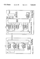
- a mobile radio communication system has a radio base station 101 and a base station controller 102A.
- the radio base station 101 is identical to the radio base station 101 shown in FIG. 2.
- the base station controller 102A differs from the base station controller 102 shown in FIG. 2 in that it has a switch circuit 8 and a plurality of CODECs 12-1, 12-2, . . . , 12-m, rather than the CODECs 12-11 ⁇ 12-13, 12-21 ⁇ 12-23, . . . , 12-n1 ⁇ 12n3.
- the number m of CODECs 12-1, 12-2, . . . , 12-m is equal to or less than the number k of output signals S1-1 ⁇ S1-k from multiplexer/demultiplexer 9.
- the multiplexer/demultiplexer 9 receives the multiplex signal of 2 Mbps from the exchange apparatus 103, demultiplexes the multiplex signal into a plurality of signals S1-1, S1-2, . . . , S1-k of 64 Kbps, and outputs the signals S1-1, S1-2, . . . , S1-k to switch circuit 7.
- Switch circuit 7 supplies the signals S1-1, S1-2, . . . , S1-k from multiplexer/demultiplexer 9 to signal lines C1, C2, . . . , Cm connected respectively to the CODECs 12-1, 12-2, . . .
- the audio signals of 64 Kbps from the exchange apparatus 103 are converted by the CODECs 12-1, 12-2, . . . , 12-m into signals of 16 Kbps, which are applied as signals d1 ⁇ dm to switch circuit 8.
- Switch circuit 8 is controlled by the control unit 13 to select the signals d1 ⁇ dm from the CODECs 12-1, 12-2, . . . , 12-m and multiplex them into a signal of 64 Kbps which is applied to switch circuit 7 through signal lines e1 ⁇ el.
- switch circuit 8 multiplexes the output signals from three of the CODECs and outputs the multiplex signal to the signal lines e1 ⁇ el in steps 32, 33. If there is one controlling time slot, switch circuit 8 multiplexes the output signals from two of the CODECs and outputs the multiplex signal to the signal line e1 ⁇ el in steps 34, 35. If there are two controlling time slots, switch circuit 8 outputs the output signal from one of the CODECs to the signal line e1 in steps 34, 36. Switch circuit 7 connects the signal lines e1 ⁇ el from switch circuit 8 to any one of the signal lines a1, a2, . . . , an of switch circuit 7 in a step 37.
- the multiplex signal is applied to the signal lines e1 ⁇ el which are connected to either one of the signal lines a1 ⁇ an by switch circuit 7. Therefore, the multiplex signal is supplied to multiplexer/demultiplexer 6, which multiplexes and transmits the supplied signal to the radio base station 101.
- the time slot signals of the multiplex signal of 2 Mbps from multiplexer/demultiplexer 6 are transmitted from the transmitter/receivers 3-1 ⁇ 3-n of the radio base station 101.
- the control unit 13 controls switch circuit 7 not to connect the CODEC corresponding to the time slot in which a control signal is transmitted over the radio communication path.
- a call connecting signal from the control signal processor 11 that is controlled by the control unit 13 is supplied through a signal line S3 to switch circuit 7, selected by switch circuit 7, supplied through a signal line a0 to multiplexer/demultiplexer 6, multiplexed by multiplexer/demultiplexer 6, and transmitted to the radio base station 101.
- the control unit 13 determines, as system parameters, the number of transmitter/receivers which transmit and receive the control signal and the number of time slots in which the control signal is transmitted and received. These system parameters may be altered during operation of the mobile radio communication system.
- the number n of the output signal lines a1 ⁇ an of switch circuit 7 and the number p of multiplex time slots of 2 Mbps between the base station controller 102A and the radio base station 101 are not the same number. Specifically, the number p is smaller than the number n (p ⁇ n).
- the digital multiplex signal from the base station controller 102A is received by multiplexer/demultiplexer 5, and demultiplexed into signals that are outputted through the respective signal lines a1 ⁇ an to the transmitter/receivers 3-1 ⁇ 3-n, respectively.
- the transmitter/receivers 3-1 ⁇ 3-n add an error correcting code to the received data TS0(R) ⁇ TS2(R) from the base station controller 102A, interleave the received data TS0(R) ⁇ TS2(R), and then transmit the processed data to the mobile stations.
- the call connecting signal transmitted from the base station controller 102A is also received by multiplexer/demultiplexer 5 and sent through a signal line a0 to the control signal processor 4.
- the control signal processor 4 supplies the control signal to a transmitter/receiver which is assigned. In response to the command from the control signal processor 4, the transmitter/receiver transmits and receives the control signal in one of the time slots.
- switch circuit 8 supplied with the output signals from the CODECs 12-1 ⁇ 12-m and switch circuit 7 supplied with signals of 64 Kbps are separate from each other in the illustrated embodiment, switch circuit 7 may be arranged to additionally perform the function of switch circuit 8.
- Switch circuit 7, which is shown as selecting the signals of 64 Kbps in the illustrated embodiment, may comprise a time-division switch (TDSW) for processing a signal of 2 Mbps applied to switch circuit 7.
- TDSW time-division switch
Landscapes
- Engineering & Computer Science (AREA)
- Computer Networks & Wireless Communication (AREA)
- Signal Processing (AREA)
- Mobile Radio Communication Systems (AREA)
- Time-Division Multiplex Systems (AREA)
Applications Claiming Priority (2)
| Application Number | Priority Date | Filing Date | Title |
|---|---|---|---|
| JP4-317636 | 1992-11-27 | ||
| JP31763692 | 1992-11-27 |
Publications (1)
| Publication Number | Publication Date |
|---|---|
| US5425031A true US5425031A (en) | 1995-06-13 |
Family
ID=18090372
Family Applications (1)
| Application Number | Title | Priority Date | Filing Date |
|---|---|---|---|
| US08/158,700 Expired - Fee Related US5425031A (en) | 1992-11-27 | 1993-11-29 | Mobile radio communication system |
Country Status (4)
| Country | Link |
|---|---|
| US (1) | US5425031A (de) |
| EP (1) | EP0599657B1 (de) |
| CA (1) | CA2110029C (de) |
| DE (1) | DE69323529T2 (de) |
Cited By (18)
| Publication number | Priority date | Publication date | Assignee | Title |
|---|---|---|---|---|
| US5568654A (en) * | 1993-10-07 | 1996-10-22 | Any Co., Ltd. | Mobile radio telecommunications system |
| US5604735A (en) * | 1995-03-15 | 1997-02-18 | Finisar Corporation | High speed network switch |
| US5615210A (en) * | 1994-01-11 | 1997-03-25 | Ntt Mobile Communications Network Inc. | Mobile radio communications system |
| US5648962A (en) * | 1993-05-25 | 1997-07-15 | Nokia Telecommunications Oy | Base station in a cellular radio system and a cellular radio system |
| US5768268A (en) * | 1995-07-19 | 1998-06-16 | Watkins Johnson Company | Wideband base station architecture for digital cellular communications system |
| US5887248A (en) * | 1995-04-03 | 1999-03-23 | Hyundai Electronics Industries Co., Ltd. | Audible tone signal service apparatus and method of a digital mobile services switching center |
| US5889769A (en) * | 1996-12-03 | 1999-03-30 | Fujitsu Limited | Switching system linked to radio base station |
| US5898683A (en) * | 1995-10-03 | 1999-04-27 | Mitsubishi Denki Kabushiki Kaisha | Base station system suitable for microcells |
| US6061354A (en) * | 1995-12-25 | 2000-05-09 | Ntt Mobile Communications Network, Inc. | Micro-frame multiplex transmitter |
| US6160823A (en) * | 1994-04-27 | 2000-12-12 | U.S. Philips Corporation | Transmission system formed by at least a base station, a mobile station and a nodal station and base station and mobile station suitable for use in such a system |
| US6172985B1 (en) | 1998-01-28 | 2001-01-09 | Gateway 2000, Inc. | Automatic detection of pots line |
| US6195566B1 (en) * | 1996-06-13 | 2001-02-27 | Lucent Technologies Inc. | Utilization of integrated base stations in the cellular radio system |
| US6292496B1 (en) * | 1995-11-15 | 2001-09-18 | Nokia Telecommunications Oy | Asynchronous data transmission method and arrangement |
| US6522640B2 (en) | 1998-01-28 | 2003-02-18 | Gateway, Inc. | Distributed modem for non-cellular cordless/wireless data communication for portable computers |
| US6580903B2 (en) | 1998-08-19 | 2003-06-17 | Infineon Technologies Ag | Circuit and method for recording and playing back voice and other sounds in digital mobile radio devices |
| US6604070B1 (en) * | 1999-09-22 | 2003-08-05 | Conexant Systems, Inc. | System of encoding and decoding speech signals |
| US6961363B1 (en) * | 1999-12-02 | 2005-11-01 | International Business Machines Corporation | Frequency look-ahead and link state history based scheduling in indoor wireless pico-cellular networks |
| US7095711B1 (en) * | 1996-07-18 | 2006-08-22 | Fujitsu Limited | Communication method and apparatus for a radio local area network system using macrodiversity |
Families Citing this family (2)
| Publication number | Priority date | Publication date | Assignee | Title |
|---|---|---|---|---|
| US5771452A (en) * | 1995-10-25 | 1998-06-23 | Northern Telecom Limited | System and method for providing cellular communication services using a transcoder |
| US5996018A (en) * | 1995-12-06 | 1999-11-30 | International Business Machines Corporation | Method and apparatus to reduce jitter and end-to-end delay for multimedia data signalling |
Citations (7)
| Publication number | Priority date | Publication date | Assignee | Title |
|---|---|---|---|---|
| EP0168647A2 (de) * | 1984-07-19 | 1986-01-22 | ANT Nachrichtentechnik GmbH | Mobilfunksystem für die Übertragung digitaler Signale |
| US4837800A (en) * | 1988-03-18 | 1989-06-06 | Motorola, Inc. | Cellular data telephone system and cellular data telephone therefor |
| US4949395A (en) * | 1989-07-07 | 1990-08-14 | Telefonaktiebolaget L M Ericsson | Method and arrangement for dynamically allocating time slots to connections in a digital mobile radio system |
| US5077741A (en) * | 1989-12-05 | 1991-12-31 | Motorola, Inc. | Data throughput enhancement |
| US5111454A (en) * | 1990-08-16 | 1992-05-05 | Motorola, Inc. | Digital cellular tdm system employing 6:1 packing of transcoded information |
| US5121391A (en) * | 1985-03-20 | 1992-06-09 | International Mobile Machines | Subscriber RF telephone system for providing multiple speech and/or data singals simultaneously over either a single or a plurality of RF channels |
| EP0536544A2 (de) * | 1991-10-07 | 1993-04-14 | Hitachi, Ltd. | System für tragbare Telefone |
-
1993
- 1993-11-25 CA CA002110029A patent/CA2110029C/en not_active Expired - Fee Related
- 1993-11-26 DE DE69323529T patent/DE69323529T2/de not_active Expired - Fee Related
- 1993-11-26 EP EP93309446A patent/EP0599657B1/de not_active Expired - Lifetime
- 1993-11-29 US US08/158,700 patent/US5425031A/en not_active Expired - Fee Related
Patent Citations (7)
| Publication number | Priority date | Publication date | Assignee | Title |
|---|---|---|---|---|
| EP0168647A2 (de) * | 1984-07-19 | 1986-01-22 | ANT Nachrichtentechnik GmbH | Mobilfunksystem für die Übertragung digitaler Signale |
| US5121391A (en) * | 1985-03-20 | 1992-06-09 | International Mobile Machines | Subscriber RF telephone system for providing multiple speech and/or data singals simultaneously over either a single or a plurality of RF channels |
| US4837800A (en) * | 1988-03-18 | 1989-06-06 | Motorola, Inc. | Cellular data telephone system and cellular data telephone therefor |
| US4949395A (en) * | 1989-07-07 | 1990-08-14 | Telefonaktiebolaget L M Ericsson | Method and arrangement for dynamically allocating time slots to connections in a digital mobile radio system |
| US5077741A (en) * | 1989-12-05 | 1991-12-31 | Motorola, Inc. | Data throughput enhancement |
| US5111454A (en) * | 1990-08-16 | 1992-05-05 | Motorola, Inc. | Digital cellular tdm system employing 6:1 packing of transcoded information |
| EP0536544A2 (de) * | 1991-10-07 | 1993-04-14 | Hitachi, Ltd. | System für tragbare Telefone |
Non-Patent Citations (7)
| Title |
|---|
| Commutation et Transmission, vol. 14, No. 1, 1992, Paris, France, pp. 21 28, XP257949 Varin et al., Alcatel 900 A paneuropean cellular radiotelephone system , p. 22, middle col., line 1 right col., line 50; FIG. 1; p. 24, middle col., line 1 p. 25, middle col., line 1; FIG. 3. * |
| Commutation et Transmission, vol. 14, No. 1, 1992, Paris, France, pp. 21-28, XP257949 Varin et al., `Alcatel 900 A paneuropean cellular radiotelephone system`, p. 22, middle col., line 1-right col., line 50; FIG. 1; p. 24, middle col., line 1-p. 25, middle col., line 1; FIG. 3. |
| European Search Report dated Oct. 20, 1994. * |
| IEICE Transactions, vol. E75, No. 12, Dec. 1992, Tokyo JP, pp. 1702 1709, XP339157 Yabusaki et al., Voice Communication Connection Control in Digital Public Land Mobile Networks , paragraph 2.2; FIG. 3. * |
| IEICE Transactions, vol. E75, No. 12, Dec. 1992, Tokyo JP, pp. 1702-1709, XP339157 Yabusaki et al., `Voice Communication Connection Control in Digital Public Land Mobile Networks`, paragraph 2.2; FIG. 3. |
| Telecom Report, vol. 15, No. 2, Apr. 1992, Munchen DE pp. 92 95, XP274593; Dittrich et al., Datenndienste im GSM Mobilfunksystem , p. 92, left col., line 26 p. 93, right col., line 28; FIGS. 1, 2. * |
| Telecom Report, vol. 15, No. 2, Apr. 1992, Munchen DE pp. 92-95, XP274593; Dittrich et al., `Datenndienste im GSM-Mobilfunksystem`, p. 92, left col., line 26-p. 93, right col., line 28; FIGS. 1, 2. |
Cited By (21)
| Publication number | Priority date | Publication date | Assignee | Title |
|---|---|---|---|---|
| US5648962A (en) * | 1993-05-25 | 1997-07-15 | Nokia Telecommunications Oy | Base station in a cellular radio system and a cellular radio system |
| US5568654A (en) * | 1993-10-07 | 1996-10-22 | Any Co., Ltd. | Mobile radio telecommunications system |
| US5615210A (en) * | 1994-01-11 | 1997-03-25 | Ntt Mobile Communications Network Inc. | Mobile radio communications system |
| US6160823A (en) * | 1994-04-27 | 2000-12-12 | U.S. Philips Corporation | Transmission system formed by at least a base station, a mobile station and a nodal station and base station and mobile station suitable for use in such a system |
| US5604735A (en) * | 1995-03-15 | 1997-02-18 | Finisar Corporation | High speed network switch |
| US5887248A (en) * | 1995-04-03 | 1999-03-23 | Hyundai Electronics Industries Co., Ltd. | Audible tone signal service apparatus and method of a digital mobile services switching center |
| US5768268A (en) * | 1995-07-19 | 1998-06-16 | Watkins Johnson Company | Wideband base station architecture for digital cellular communications system |
| US5898683A (en) * | 1995-10-03 | 1999-04-27 | Mitsubishi Denki Kabushiki Kaisha | Base station system suitable for microcells |
| CN1097992C (zh) * | 1995-10-03 | 2003-01-01 | 三菱电机株式会社 | 基站系统 |
| US6292496B1 (en) * | 1995-11-15 | 2001-09-18 | Nokia Telecommunications Oy | Asynchronous data transmission method and arrangement |
| US6061354A (en) * | 1995-12-25 | 2000-05-09 | Ntt Mobile Communications Network, Inc. | Micro-frame multiplex transmitter |
| US6195566B1 (en) * | 1996-06-13 | 2001-02-27 | Lucent Technologies Inc. | Utilization of integrated base stations in the cellular radio system |
| US7095711B1 (en) * | 1996-07-18 | 2006-08-22 | Fujitsu Limited | Communication method and apparatus for a radio local area network system using macrodiversity |
| US5889769A (en) * | 1996-12-03 | 1999-03-30 | Fujitsu Limited | Switching system linked to radio base station |
| US6172985B1 (en) | 1998-01-28 | 2001-01-09 | Gateway 2000, Inc. | Automatic detection of pots line |
| US6522640B2 (en) | 1998-01-28 | 2003-02-18 | Gateway, Inc. | Distributed modem for non-cellular cordless/wireless data communication for portable computers |
| US6580903B2 (en) | 1998-08-19 | 2003-06-17 | Infineon Technologies Ag | Circuit and method for recording and playing back voice and other sounds in digital mobile radio devices |
| US6604070B1 (en) * | 1999-09-22 | 2003-08-05 | Conexant Systems, Inc. | System of encoding and decoding speech signals |
| US6735567B2 (en) | 1999-09-22 | 2004-05-11 | Mindspeed Technologies, Inc. | Encoding and decoding speech signals variably based on signal classification |
| US6961363B1 (en) * | 1999-12-02 | 2005-11-01 | International Business Machines Corporation | Frequency look-ahead and link state history based scheduling in indoor wireless pico-cellular networks |
| USRE43494E1 (en) * | 1999-12-02 | 2012-06-26 | Wistron Corporation | Frequency look-ahead and link state history based scheduling in indoor wireless pico-cellular networks |
Also Published As
| Publication number | Publication date |
|---|---|
| EP0599657B1 (de) | 1999-02-17 |
| CA2110029A1 (en) | 1994-05-28 |
| CA2110029C (en) | 1997-05-06 |
| DE69323529D1 (de) | 1999-03-25 |
| EP0599657A3 (de) | 1994-12-07 |
| EP0599657A2 (de) | 1994-06-01 |
| DE69323529T2 (de) | 1999-10-21 |
Similar Documents
| Publication | Publication Date | Title |
|---|---|---|
| US5425031A (en) | Mobile radio communication system | |
| EP0485593B1 (de) | Datenmultiplexer mit der möglichkeit von gleichzeitiger verarbeitung von mehreren kanälen | |
| US4686667A (en) | Broadband integrated subscriber loop system | |
| EP0159810B1 (de) | Breitbandiges digitales Übertragungssystem | |
| CA2037140C (en) | Multidirection multiplex communication system | |
| US6052365A (en) | Multi-channel digital data transmission in a wireless telecommunications system | |
| US5684806A (en) | Communication apparatus for TDMA system | |
| US4603415A (en) | System for linking channel group in digital communication network | |
| US5422949A (en) | Subscriber terminal apparatus | |
| US5754836A (en) | Split bus architecture for multipoint control unit | |
| JP2565117B2 (ja) | 移動通信システム | |
| JPH089058A (ja) | 伝送路バックアップ機能付の多重化装置 | |
| US5761207A (en) | Multiplex communication system using variable multiframe format | |
| JP2535940B2 (ja) | 多方向多重通信システム | |
| KR100251590B1 (ko) | 통신채널의 전송효율을 향상시킨 광 catv 시스템 | |
| JP3105764B2 (ja) | 多方向多重接続方式の無線通信システム | |
| JP2535939B2 (ja) | 多方向多重通信システム | |
| JPH0779321B2 (ja) | フレーム伝送方法 | |
| JP2907661B2 (ja) | デジタル多重伝送装置 | |
| JPH08331081A (ja) | 多方向多重接続方式の無線通信システム | |
| JPS6218119B2 (de) | ||
| JPS60153697A (ja) | 共通線信号回線収容方式 | |
| JPH02264552A (ja) | テレビジョン会議装置 | |
| GB2188213A (en) | Improvements in or relating to communications systems | |
| JPH0946498A (ja) | 同報通信システムおよびこれに用いる送信装置と受信装置 |
Legal Events
| Date | Code | Title | Description |
|---|---|---|---|
| AS | Assignment |
Owner name: NEC CORPORATION, JAPAN Free format text: ASSIGNMENT OF ASSIGNORS INTEREST;ASSIGNOR:OTSUKA, SHIGERU;REEL/FRAME:006799/0361 Effective date: 19931119 |
|
| FEPP | Fee payment procedure |
Free format text: PAYOR NUMBER ASSIGNED (ORIGINAL EVENT CODE: ASPN); ENTITY STATUS OF PATENT OWNER: LARGE ENTITY |
|
| FPAY | Fee payment |
Year of fee payment: 4 |
|
| FPAY | Fee payment |
Year of fee payment: 8 |
|
| REMI | Maintenance fee reminder mailed | ||
| LAPS | Lapse for failure to pay maintenance fees | ||
| STCH | Information on status: patent discontinuation |
Free format text: PATENT EXPIRED DUE TO NONPAYMENT OF MAINTENANCE FEES UNDER 37 CFR 1.362 |
|
| FP | Lapsed due to failure to pay maintenance fee |
Effective date: 20070613 |