US5319419A - Scanning system driving device - Google Patents
Scanning system driving device Download PDFInfo
- Publication number
- US5319419A US5319419A US07/982,769 US98276992A US5319419A US 5319419 A US5319419 A US 5319419A US 98276992 A US98276992 A US 98276992A US 5319419 A US5319419 A US 5319419A
- Authority
- US
- United States
- Prior art keywords
- scanning system
- electromagnetic clutch
- scanning
- driving
- time
- Prior art date
- Legal status (The legal status is an assumption and is not a legal conclusion. Google has not performed a legal analysis and makes no representation as to the accuracy of the status listed.)
- Expired - Fee Related
Links
Images


Classifications
-
- G—PHYSICS
- G03—PHOTOGRAPHY; CINEMATOGRAPHY; ANALOGOUS TECHNIQUES USING WAVES OTHER THAN OPTICAL WAVES; ELECTROGRAPHY; HOLOGRAPHY
- G03G—ELECTROGRAPHY; ELECTROPHOTOGRAPHY; MAGNETOGRAPHY
- G03G15/00—Apparatus for electrographic processes using a charge pattern
- G03G15/04—Apparatus for electrographic processes using a charge pattern for exposing, i.e. imagewise exposure by optically projecting the original image on a photoconductive recording material
- G03G15/043—Apparatus for electrographic processes using a charge pattern for exposing, i.e. imagewise exposure by optically projecting the original image on a photoconductive recording material with means for controlling illumination or exposure
Definitions
- the present invention relates generally to a scanning system driving device used in an image forming apparatus, having a scanning system for illuminating and scanning a document, such as a copying machine or an image scanner, and more particularly, to an improvement in transmission control of a driving force of the scanning system driving device.
- a scanning system As a scanning system provided for a copying machine or the like, there are two types of scanning systems: a scanning system in which an optical system is moved relative to a still document, and a scanning system in which a document platen is moved relative to a still optical system.
- the term "scanning system" is used as a general term for the above described two types of scanning systems. Consequently, a scanning system driving device includes both a device for moving and controlling an optical system and a device for moving and controlling a document platen.
- An image forming apparatus such as a copying machine includes a scanning system for optically scanning a document by driving an optical system or a document platen.
- a scanning system for optically scanning a document by driving an optical system or a document platen.
- a moving body holding a light source and a reflecting mirror is displaced at uniform speed relative to a document. Consequently, the surface of the document is illuminated and scanned.
- a photoreceptor is exposed by light reflected from the document, and an electrostatic latent image is formed on the surface of the photoreceptor.
- This electrostatic latent image is developed into a toner image, and the toner image is transferred and fixed to copy paper, to achieve copying.
- the electrostatic latent image formed on the surface of the photoreceptor is formed by the light reflected from the document illuminated and scanned.
- the moving distance of the scanning system from the home position to the position where illumination and scanning are started is short. Therefore, it is necessary to rapidly increase the moving speed of the scanning system. If the moving speed of the scanning system is thus rapidly increased so-called overshoot is produced. That is, the speed of the scanning system once exceeds the rated speed immediately before the speed of the scanning system reaches the rated speed. This overshoot degrades the copy image corresponding to the region in the vicinity of the position where illumination and scanning are started. Consequently, care must be taken to exclude the effect of the overshoot.
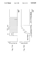
- FIG. 11 A prior art technique in which the moving speed of a scanning system is rapidly increased and a copy image is not affected by overshoot is shown in FIG. 11.
- a driving force on the scanning system is supplied from a main motor, provided in the copying machine, through an electromagnetic clutch.
- FIG. 11(a) shows the change with time of the voltage applied to the electromagnetic clutch
- FIG. 11(b) shows the change with time of the moving speed of the scanning system.
- the voltage applied to the electromagnetic clutch is instantaneously increased to a predetermined rated voltage at the time of starting the scanning system, as shown in FIG. 11(a).
- This predetermined rated voltage is a voltage applied to the electromagnetic clutch when the scanning system is driven at rated speed so as to illuminate and scan a document.
- an idle period is a period elapsed from the time when the rotation of the main motor is started until the electromagnetic clutch is connected
- an approach period is a period elapsed from the time when the scanning system is in the home position until it reaches the position where illumination and scanning are started
- an image forming period is a period during which the document is illuminateded and scanned.
- the electromagnetic clutch is instantaneously connected, so that the driving force from the main motor is impulsively transmitted to the scanning system.
- the moving speed of the scanning system fluctuates, as shown in FIG. 11(b). If the moving speed vibrates, excellent image formation is not carried out. Consequently, a period during which the moving speed vibrates is taken as an approach period, and a period after the moving speed is stabilized is taken as an image forming period.
- FIG. 12 This problem is solved by another prior art technique shown in FIG. 12.
- a applied to an electromagnetic clutch is gradually increased, as shown in FIG. 12(a), Therefore, a driving force from a main motor is gently transmitted to a scanning system.
- the moving speed of the scanning system is smoothly increased and stabilized at rated speed in a short time, as shown in FIG. 12(b). Consequently, no long approach distance is required, thereby making it possible to miniaturize the copying machine, unlike the prior art technique shown in FIG. 11.
- An object of the present invention is to provide a scanning system driving device which does not have vibration immediately after the rise of a scanning system, while decreasing the approach distance of the scanning system.
- a rated voltage is applied in the form of pulses to an electromagnetic clutch for transmitting a driving force from a driving source to a scanning system at intervals of such OFF time that the connecting force of the electromagnetic clutch is decreased to reduce the rising speed of the scanning system once at the time of starting scanning by the scanning system.
- the electromagnetic clutch is brought into a half connected state from a disconnected state, and the connecting force of the electromagnetic clutch is repeatedly increased and/or decreased in this half connected state. That is, the electromagnetic clutch is not repeatedly connected and/or disconnected.
- the scanning system can be gently started.
- the moving speed of the scanning system can be quickly stabilized. Consequently, the approach distance of the scanning system is decreased.
- the fluctuation of the moving speed of the scanning system can be restrained.
- FIG. 1 is a schematic diagram illustrating the internal construction of a copying machine to which an embodiment of the present invention is applied;
- FIG. 2 is a plan view illustrating the construction of a scanning system driving device
- FIG. 3 is a diagram showing the gears in the driving device meshed with each other
- FIG. 4 (a) is a diagram showing the state of an electromagnetic clutch at the time of forward rotation
- FIG. 4 (b) is a diagram showing the state of the electromagnetic clutch at the time of reverse rotation
- FIG. 5 is a block diagram of the scanning system driving device
- FIG. 6 (a) is a waveform diagram showing a voltage applied to the electromagnetic clutch at the time of starting a scanning system in a first embodiment of the present invention
- FIG. 6 (b) is a diagram showing the change with time of the moving speed of the scanning system at the time of starting the scanning system in the first embodiment of the present invention:
- FIG. 7 (a) is a waveform diagram showing a voltage applied to an electromagnetic clutch at the time of starting a scanning system in a second embodiment of the present invention
- FIG. 7 (b) is a diagram showing the change with time of the moving speed of the scanning system at the time of starting the scanning system in the second embodiment of the present invention.
- FIG. 8 (a) is a waveform diagram showing a voltage applied to an electromagnetic clutch at the time of starting a scanning system in a third embodiment of the present invention.
- FIG. 8 (b) is a diagram showing the change with time of the moving speed of the scanning system at the time of starting the scanning system in the third embodiment of the present invention.
- FIG. 9 (a) is a waveform diagram showing a voltage applied to an electromagnetic clutch at the time of starting a scanning system in a fourth embodiment of the present invention.
- FIG. 9 (b) is a diagram showing the change with time of the moving speed of the scanning system at the time of starting the scanning system in the fourth embodiment of the present invention.
- FIG. 10 (a) is a waveform diagram showing a voltage applied to an electromagnetic clutch at the time of starting a scanning system in a fifth embodiment of the present invention.
- FIG. 10 (b) is a diagram showing the change with time of the moving speed of the scanning system at the time of starting the scanning system in the fifth embodiment of the present invention.
- FIG. 11 (a) is a waveform diagram showing a voltage applied to an electromagnetic clutch in a conventional scanning system driving device in which the approach period of a scanning system is made long
- FIG. 11 (b) is a diagram showing the change with time of the moving speed of the scanning system in the prior art device
- FIG. 12 (a) is a waveform diagram showing a voltage applied to an electromagnetic clutch in a conventional scanning system driving device in which a voltage applied to the electromagnetic clutch is gradually increased
- FIG. 12 (b) is a diagram showing the change with time of the moving speed of a scanning system in the prior art device.
- FIG. 1 is a conceptual diagram illustrating the internal construction of a copying machine to which a scanning system driving device according to an embodiment of the present invention is applied.
- An internal space within a main body 1 of the copying machine is partitioned into an upper casing 12 and a lower casing 13 by a partitioning plate 11.
- an optical system 2 having a predetermined inertial mass, which is a scanning system for illuminating and scanning a document.
- the lower casing 13 there are provided a copying section 4, for forming a copy image on copy paper P, and a copy paper conveying section 5.
- the optical system 2 comprises a light source 21 constituted by an illuminant 31 and a main reflector 32, first, second and third reflecting mirrors 22, 23 and 24, a lens 25, and a fourth reflecting mirror 26.
- the optical system 2 is so constructed that a document D on a document platen 14, constituted by a transparent platen or the like, can be illuminated and scanned by moving the light source 21 and the first to third reflecting mirrors 22, 23 and 24 in the direction indicated by an arrow A along guide shafts 27a and 27b and a guide rail (not shown).
- the light source 21 and the first reflecting mirror 22 integrally reciprocate
- the second reflecting mirror 23 and the third reflecting mirror 24 integrally reciprocate.
- the copy paper conveying section 5 comprises paper feeding rollers 51 and 52, paper feeding paths 53 and 54, delivery rollers 55a and 55b, a registration roller 56, a delivery belt 57, a heating and fixing roller 58, and a discharge roller 59.
- the copy paper conveying section 5 is so constructed as to selectively drive the paper feeding rollers 51 and 52 to take out the copy paper P from a paper feeding cassette 16 or 17, introduce the copy paper P into the copying section 4 to transfer a toner image, heat and fix the toner image by the heating and fixing roller 58 and then, discharge the copy paper P onto a discharge tray 18.
- the copy paper conveying section 5 is not limited to this construction. For example, it is possible to also use a copy paper conveying section of another construction conventionally known, for example, such construction that paper is fed and discharged on the same side.
- the copying section 4 is constructed by arranging a charging corona discharger 42, a developing device 43, a transferring corona discharger 44, a separating corona discharger 45 and a cleaner 46 in this order around a photosensitive drum 41 rotated in the direction indicated by an arrow C.
- the copying section 4 is so constructed as to form a document image on the outer surface of the photosensitive drum 41 uniformly charged by the charging corona discharger 42 to form an electrostatic latent image and then, develop the electrostatic latent image into a toner image by the developing device 43, and transfer the toner image onto the copy paper P by the transferring corona discharger 44. Toner remaining on the surface of the photosensitive drum 41, after the toner image is transferred, is recovered by the cleaner 46.
- the copying section is not limited to this construction. For example, it is possible to also use a copying section of another construction conventionally known, for example, a copying section using a photoreceptor in a belt shape.
- FIG. 2 is a plan view illustrating in detail the construction of a scanning system driving device.
- a driving device 100 comprises a driving wire 101 stretched between scanning regions, a moving body 102 mounted at a predetermined position of the driving wire 101 and holding respective components of the optical system 2, a wire-wound drum 103 around which the driving wire 101 is wound, an electromagnetic clutch for forward rotation 104 for transmitting a driving force to the wire-wound drum 103 to rotate the drum 103 in the forward rotation to move the moving body 102 in the direction L, and an electromagnetic clutch for reverse rotation 105 for transmitting the driving force to the wire-wound drum 103 to rotate the drum 103 in the reverse direction to move the moving body 102 in the direction R.
- the major specifications of the micro clutch are as follows.
- the moving body 102 comprises a first mirror box 61, for supporting a light source 21 and a first reflecting mirror 22, and a second mirror box 62, for supporting a second reflecting mirror 23 and a third reflecting mirror 24 (see FIG. 1).
- the moving body 102 is fixed at a predetermined position of the driving wire 101 on the side of the first mirror box 61.
- the moving body 102 is provided with a guide pulley 106 on the side of the second mirror box 62.
- the driving wire 101 is fixed to the end of the scanning region in the direction R in its end, in its end, is wound around a guide pulley 106 on the moving body 102, is wound around a pulley 107, is wound around the wire-wound drum 103 a plurality of times, is further wound around a pulley 108, is again wound around the guide pulley 106, and is fixed through a spring 109 to the other end of the scanning region in the direction L.
- the electromagnetic clutch for forward rotation 104 (FIG. 4) comprises a clutch gear 112, which is meshed with a driving gear 111 connected to a main motor 110 (see FIG. 5) and is always rotated, and a driven gear 113, which is provided on the same shaft with the clutch gear 112 and can be rotated independently from the clutch gear 112.
- the electromagnetic clutch for forward rotation 104 is so constructed as to attract the driven gear 113 toward the clutch gear 112 by an electromagnetic coil (not shown) contained therein to bring the driven gear 113 into frictional contact with the clutch gear 112 through a suitable friction plate (not shown) and transmit the driving force applied to the clutch gear 112 to the driven gear 113 by the frictional force.
- the electromagnetic clutch for reverse rotation 105 comprises a clutch gear 114, which is meshed with the driving gear 111 connected to the main motor 110 and is always rotated, and a driven gear 115 which is provided on the shaft of the clutch gear 114 and can be rotated independently from the clutch gear 114.
- the electromagnetic clutch for reverse rotation 105 is so constructed as to attract the driven gear 115 toward the clutch gear 114 by an electromagnetic coil (not shown) contained therein to bring the driven gear 115 into frictional contact with the clutch gear 114 through a suitable friction plate (not shown) and transmit a driving force applied from the clutch gear 114 to the driven gear 115 by the frictional force.
- the driven gear 113 in the electromagnetic clutch for forward rotation 104 is meshed with the driven gear 115 in the electromagnetic clutch for reverse rotation 105, and the driven gear 115 is meshed with the wire-wound drum 103, as shown in FIG. 4.
- the electromagnetic clutch for forward rotation 104 and the electromagnetic clutch for reverse rotation 105 respectively have connecting forces which vary depending on the magnitude of the average applied voltage per unit time until the clutch is brought into a completely connected state.
- the electromagnetic clutches 104 and 105 can be brought into a half connected state, which is an intermediate state between a disconnected state and a completely connected state, depending on the relationship among the connecting force, the inertial mass of the optical system 2 and the driving force from the main motor 110.
- the disconnected state is a state where the driving force from the main motor 110 is not entirely transmitted to the moving body 102.
- the completely connected state is a state where the driving force from the main motor 110 is directly transmitted to the moving body 102.
- Either one of the electromagnetic clutch for forward rotation 104 and the electromagnetic clutch for reverse rotation 105 is selected to be brought into a connected state, thereby to make it possible to perform a forward rotation operation or a reverse rotation operation as shown in FIG. 3. More specifically, as shown in FIG. 4 (a), if the electromagnetic clutch for forward rotation 104 is brought into a connected state, while the electromagnetic clutch for reverse rotation 105 is not, torque from the clutch gear 112 is transmitted to the driven gear 113, and is further transmitted to the wire-wound drum 103 through the driven gear 115 which is in a freely rotated state. Accordingly, the wire-wound drum 103 is rotated in the direction of forward rotation as shown in FIG. 3.
- the first mirror box 61 and the second mirror box 62 are driven in the direction L as shown in FIG. 2.
- the electromagnetic clutch for reverse rotation 105 is brought into a connected state, while the electromagnetic clutch for forward rotation 104 is not, torque from the clutch gear 114 is transmitted to the wire-wound drum 103 from the driven gear 115.
- the driven gear 113 meshed with the driven gear 115 only follows the rotation of the driven gear 115. Therefore, the wire-wound drum 103 is rotated in the direction of reverse rotation shown in FIG. 3.
- the moving body 102 is driven in the direction R shown in FIG. 2.
- a clutch gear having a smaller number of teeth than those of the clutch gear for forward rotation 112 is applied to the clutch gear for reverse rotation 114, thereby to perform at high speed the return operation at high speed when the first mirror box 61 and the second mirror box 62 have terminated scanning for image formation and are returned to the home position.
- FIG. 5 is a functional block diagram showing the electrical components for controlling the above described driving device.
- the connection and the disconnection of both the electromagnetic clutches 104 and 105 are controlled by a control circuit 200.
- Operating power of the control circuit 200 is produced in a power circuit 300.
- a print switch 301, for initiating the start of a copying operation, and an output circuit 304, for turning on and/or off the main motor 110, are further connected to the control circuit 200.
- the power circuit 300 generates a rated voltage to be applied to the electromagnetic clutches 104 and 105.
- This rated voltage is a voltage which is continuously applied to the electromagnetic clutches 104 and 105 over not less than a predetermined time to allow the electromagnetic clutches 104 and 105 to be brought into a completely connected state.
- the application of the rated voltage is controlled by the control circuit 200.
- FIG. 6 (a) is a waveform diagram showing a waveform of a voltage applied to the electromagnetic clutch for forward rotation 104 by the control circuit 200 in the early stages of scanning
- FIG. 6 (b) is a diagram showing the change with time of the moving speed of the moving body 102 (the first mirror box 61). If the print switch 301 is turned on, an operation signal from the print switch 301 is inputted to the control circuit 200. The control circuit 200 energizes the main motor 110 through the output circuit 304 in response to the operation signal. In addition, the control circuit 200 applies a pulse voltage to the electromagnetic clutch for forward rotation 104 during at least an approach period extending from the time when the moving body 102 is in the home position to the time when body 102 has reached the position where illumination and scanning are started.
- the control circuit 200 applies a pulse voltage having constant ON time ⁇ ON to the electromagnetic clutch for forward rotation 104 at intervals of OFF time ⁇ OFF by switching the above described rated voltage generated by the power circuit 300.
- the OFF time ⁇ OFF is a time such that the connecting force of the electromagnetic clutch for forward rotation 104 can be decreased to reduce the moving speed of the moving body 102 once.
- This OFF time ⁇ OFF may be a constant value or a value varying depending on the passage of time or the position of the moving body 102.
- a pulse waveform shown in FIG. 6 (a) is one example. In this example, the OFF time ⁇ OFF is 5 msec and is constant.
- the ON time ⁇ ON is 5 msec. Such a pulse voltage is continuously applied only for a period of, for example, nine pulses. It is preferable that the ON time ⁇ ON be not more than 30 msec so that the electromagnetic clutch for forward rotation 104 is not brought into a completely connected state instantaneously by application of one pulse.
- the moving speed of the moving body 102 is gradually increased without causing so large a fluctuation, and can be stabilized at the rated speed at the end of the approach period. As a result, the moving body 102 can be gently started in the direction L shown in FIG. 2.
- the ON time ⁇ ON and the OFF time ⁇ OFF so that the fluctuation of the moving speed of the moving body 102 is such as to restrain the natural vibration of the optical system 2 in consideration of, for example, the gear pitches of the clutch gear 112 and the driven gear 113. Consequently, the natural vibration of the optical system 2 can be restrained, thereby making it possible to improve the image quality.
- the control circuit 200 continuously applies a rated voltage to the electromagnetic clutch for forward rotation 104. Consequently, the moving body 102 is moved at a uniform speed by the driving force obtained from the main motor 110. If the moving body 102 reaches the terminal position in the direction L, the electromagnetic clutch for forward rotation 104 is turned off, and the control circuit 200 continuously applies the rated voltage to the electromagnetic clutch for reverse rotation 105. Consequently, the moving body 102 is moved at uniform speed in the direction R (see FIG. 2) to perform a return operation.
- the moving body 102 At the end of the return operation, the moving body 102 reaches the approach region again through the image forming region. At this time, the control circuit 200 applies a predetermined pulse voltage to the electromagnetic clutch for reverse rotation 105.
- This pulse voltage is such a voltage that the connecting force between the clutch gear 114 in the electromagnetic clutch for reverse rotation 105 and the driving gear 111 can be gradually decreased. Consequently, the moving body 102 is smoothly decelerated, to be stopped in the home position. Thereafter, the control circuit 200 turns the main motor 110 off through the output circuit 304.
- the pulse voltage having constant ON time is continuously applied to the electromagnetic clutch for forward rotation 104 at intervals of such OFF time that the connecting force of the electromagnetic clutch 104 can be decreased to reduce the speed of the moving body 102 once. More specifically, the pulse voltage is applied to the electromagnetic clutch 104 to gradually increase the connecting force of clutch 104 by repeating increase and decrease. Therefore, the driving force is gradually transmitted to the moving body 102 to allow the moving speed of the moving body 102 to smoothly increase. An amount of slip between the pair of friction plates of the electromagnetic clutch for forward rotation 104 is decreasing as the moving speed of the moving body 102 is increasing.
- the moving speed of the moving body 102 can be increased to the rated speed over a short approach distance and stabilized. Consequently, the scanning system driving device according to the present embodiment is favorable for miniaturization of the copying machine and can prevent degradation of an image. Moreover, no such complicated circuit as to continuously change the voltage applied to the electromagnetic clutch is required, so that the construction is not complicated and the cost is not excessively increased.
- the scanning system driving device can be so constructed that a memory 310 (see FIG. 5), storing a plurality of types of waveforms of a pulse voltage applied to the electromagnetic clutch for forward rotation 104 or the electromagnetic clutch for reverse rotation 105, is provided for the control circuit 200, and each of the pulse waveforms is selected by, for example, a dip switch 311 (see FIG. 5).
- a dip switch 311 see FIG. 5
- the pulse waveform can be stored by storing a waveform itself.
- a plurality of types of ON time ⁇ ON and OFF time ⁇ OFF may be stored.
- the pulse waveform may be selected by an operation of a section other than the dip switch 311, for example, a keying section provided for the copying machine.
- FIG. 7(a) is a waveform diagram showing a waveform of a voltage applied to the electromagnetic clutch for forward rotation 104 by the control circuit 200 in the early stages of the movement of the moving body 102
- FIG. 7(b) is a diagram showing the change with time of the moving speed of the moving body 102.
- control circuit 200 When an operator turns the print switch 301 on, an operation signal from the print switch 301 is inputted to the control circuit 200.
- the control circuit 200 turns the main motor 110 on through the output circuit 304 in response to the operation signal, and further applies a pulse voltage to the electromagnetic clutch for forward rotation 104 over a period extending until the moving body 102 reaches the position where illumination and scanning are started.
- a first pulse P1 having, relatively long ON time ⁇ L ON , is applied to the electromagnetic clutch for forward rotation 104.
- a pulse voltage having constant ON time ⁇ S ON relatively shorter than the ON time ⁇ L ON of the first pulse P1 is applied to the electromagnetic clutch for forward rotation 104 at intervals of OFF time ⁇ OFF .
- the OFF time ⁇ OFF is such time that the connecting force of the electromagnetic clutch for forward rotation 104 can be decreased to reduce the increasing speed of the scanning system once.
- the OFF time ⁇ OFF may be a constant value or a value varying depending on the passage of time and the position of the moving body 102.
- the pulse waveform shown in FIG. 7(a) is one example.
- the OFF time ⁇ OFF is 5 msec and is constant.
- the ON time ⁇ S ON is 5 msec.
- Such a pulse voltage is continuously applied only for a period of, for example, seven pulses.
- the ON time ⁇ L ON of the first pulse P1 is so set that a clearance between friction surfaces of the clutch gear 112 and the driven gear 113 is reduced down to zero and the connecting force between the clutch gear 112 and the driven gear 113 is 20 to 50 per cent of the maximum value of the connecting force.
- the clearance between the friction surfaces of the clutch gear 112 and the driven gear 113 in the electromagnetic clutch for forward rotation 104 is first reduced down to zero by a pulse voltage corresponding to the first pulse P1. Thereafter, the pulse voltage having relatively short ON time ⁇ S ON is applied to the electromagnetic clutch for forward rotation 104, thereby to make it possible to gently start the moving body 102 without causing so large a fluctuation of the moving speed of the moving body 102.
- the moving speed of the moving body 102 can be increased to the rated speed a relatively short approach distance and stabilized.
- the clearance between the clutch gear 112 and the driven gear 113 in the electromagnetic clutch 104 is reduced instantaneously by the application of the first pulse P1, thereby not only to shortening the approach period but also shortening the idle period.
- the behavior of the moving body 102 in the approach period is effectively inhibited from varying due to differences in attraction characteristics between electromagnetic clutches used as the clutch 104. Further, an abnormal sound produced by repeatedly connecting and/or disconnecting the electromagnetic clutch 104 is also prevented.
- the attraction characteristics of electromagnetic clutch 104 are of interest in a case where the driven gear 113 is attracted toward the clutch gear 112.
- the On time ⁇ L ON and ⁇ S ON and the OFF time ⁇ OFF is such as to restrain the natural vibration of the optical system 2 in consideration of, for example, the gear pitches of the clutch gear 112 and the driven gear 113. Consequently, the natural vibration of the optical system 2 can be restrained, thereby making it possible to improve the image quality.
- the control circuit 200 continuously applies a rated voltage to the electromagnetic clutch for forward rotation 104. Consequently, the moving body 102 is moved at uniform speed by the driving force obtained from the main motor 110. If the moving body 102 reaches the terminal position in the direction L, the electromagnetic clutch for forward rotation 104 is turned off, and the control circuit 200 continuously applies the rated voltage to the electromagnetic clutch for reverse rotation 105. Therefore, the moving body 102 is moved at uniform speed in the direction R (see FIG. 2), to perform a return operation.
- the moving body 102 At the end of the return operation, the moving body 102 reaches the approach region again, beyond the position where illumination and scanning were started. At this time, the control circuit 200 applies a predetermined pulse voltage to the electromagnetic clutch for reverse rotation 105. This pulse voltage is such a voltage that the connecting force between the clutch gear 114 in the electromagnetic clutch for reverse rotation 105 and the driving gear 111 can be gradually decreased. Consequently, the moving body 102 is smoothly decelerated, to be stopped in the home position. Thereafter, the control circuit 200 turns the main motor 110 off through the output circuit 304.
- the pulse voltage having a relatively long ON time ⁇ L ON is first applied to the electromagnetic clutch for forward rotation 104, thereby to reduce the clearance between the friction surfaces in the electromagnetic clutch 104 down to zero. Thereafter, the pulse voltage having constant ON time ⁇ S ON is continuously applied to the electromagnetic clutch 104 at intervals of OFF time ⁇ OFF such that the connecting force of the electromagnetic clutch 104 is decreased to reduce the speed of the moving body 102 once. Consequently, the electromagnetic clutch 104 is gradually connected. Therefore, it is possible to stabilize the moving speed of the moving body 102 at the rated speed over a short approach distance.
- the scanning system driving device is favorable for miniaturization of the copying machine and can prevent degradation of, an image. Moreover, no complicated circuit, such as to continuously change a voltage applied to an electromagnetic clutch, is required, so that the construction is not complicated and the cost is not excessively increased.
- the scanning system driving device can be so constructed that a memory 310 (see FIG. 5), storing a plurality of types of waveforms of a pulse voltage applied to the electromagnetic clutch for forward rotation 104 or the electromagnetic clutch for reverse rotation 105, is provided for the control circuit 200, and each of the pulse waveforms is selected by, for example, a dip switch 311 (see FIG. 5). If this construction is adopted, it is possible to select by the dip switch 311 at the time of shipment of products a pulse waveform corresponding to the performance of the electromagnetic clutch 104 or 105 used in each of the products, and to select by the dip switch 311 at the time of maintenance a pulse waveform corresponding to the performance of the electromagnetic clutch 104 or 105 changed with time. Consequently, the rise characteristics of the moving speed of the moving body 102 are inhibited from varying due to differences in performance between electromagnetic clutches used as clutch 104.
- the pulse waveform can be stored by storing a waveform itself.
- a plurality of types of ON time ⁇ S ON and OFF time ⁇ OFF , as well as ON time ⁇ L ON of the first pulse P1 may be stored.
- the pulse waveform may be selected by an operation of a section other than the dip switch 311, for example, a keying section provided for the copying machine.
- the scanning system driving device is so constructed that there is provided an electromagnetic brake for stopping the movement of the scanning system, and a pulse voltage having a relatively long ON time is first applied to the electromagnetic brake when the scanning system is stopped, and then a pulse voltage having a relatively short ON time is applied thereto until the moving body 102 is stopped, it is possible to gently stop the moving body 102.
- FIG. 8(a) is a waveform diagram showing a waveform of a voltage applied to the electromagnetic clutch for forward rotation 104 by the control circuit 200 in the early stages of the movement of the moving body 102
- FIG. 8(b) is a diagram showing the change with time of the moving speed of the moving body 102.
- control circuit 200 When an operator turns the print switch 301 on, an operation signal from the print switch 301 is inputted to the control circuit 200.
- the control circuit 200 turns the main motor 110 on through the output circuit 304 in response to the operation signal, and further applies a pulse voltage to the electromagnetic clutch for forward rotation 104 over a period extending until the moving body 102 reaches the position where illumination and scanning are started.
- the control circuit 200 applies a pulse voltage having constant ON time ⁇ ON to the electromagnetic clutch for forward rotation 104 at intervals of constant OFF time ⁇ OFF .
- the OFF time ⁇ OFF is such time that the connecting force of the electromagnetic clutch 104 can be slightly decreased to reduce the speed of the moving body 102 once.
- the OFF time ⁇ OFF in this period T1 may be a constant value or a value varying depending on the elapse of time and the position of the moving body 102.
- the pulse waveform shown in FIG. 8(a) is one example.
- the OFF time ⁇ OFF in the period T1 is 5 msec and which is constant.
- the ON time ⁇ ON in the period T1 is 5 msec.
- Such a pulse voltage is continuously applied only for a period of, for example, seven pulses.
- a pulse voltage having ON time ⁇ ON is applied to the electromagnetic clutch for forward rotation 104.
- the pulse content is gradually increased.
- the ON time ⁇ ON of an eighth pulse P8 is 6 msec
- OFF time ⁇ OFF subsequent to the eighth pulse P8 is 4 msec.
- the ON time ⁇ ON of a ninth pulse P9 is 7 msec
- OFF time ⁇ OFF subsequent thereto is 3 msec.
- the ON time ⁇ ON of a tenth pulse P10 is 8 msec
- OFF time ⁇ OFF subsequent thereto is 2 msec.
- the pulse content is thus gradually increased, thereby making it possible to completely attract the driven gear 113 toward the clutch gear 112 in the electromagnetic clutch for forward rotation 104.
- the electromagnetic clutch 104 can be brought into a completely connected state before the moving body 102 reaches the position where illumination and scanning are started. In the image forming period during which a document is illuminated and scanned, therefore, the electromagnetic clutch 104 is reliably in the completely connected state.
- the OFF time ⁇ OFF is set to have such a length that the connecting force between the clutch gear 112 and the driven gear 113 in the electromagnetic clutch for forward rotation 104 can be slightly decreased in the period T1, which is the idle period and the first half to the middle of the approach period. As shown in FIG. 8(b), therefore the moving speed of the moving body 102 is gradually increased without causing a large fluctuation, and is quickly stabilized. Consequently, the moving body 102 can be gently started in the direction L shown in FIG. 2.
- the pulse content of the pulse voltage applied to the electromagnetic clutch 104 is gradually increased in the period T2, which is the second half to the end of the approach period, is gradually increased, so that the electromagnetic clutch 104 is in the completely connected state before the moving body 102 reaches the position where illumination and scanning are started.
- the driving force from the main motor 110 can be stably transmitted to the moving body 102.
- the electromagnetic clutch 104 leads to the completely connected state. Even when there are differences in performance, such as the magnitude of torque, between electromagnetic clutches for forward rotation 104, therefore, it is possible to stably drive the moving body 102 in the direction L (see FIG. 2), before control at the time of starting of scanning is terminated. Even when the behavior of the moving body 102 at the time of increasing the moving speed varies due to the differences in performance between electromagnetic clutches for forward rotation 104, therefore, the document can be stably scanned at uniform speed in the image forming period subsequent to the approach period.
- the ON time ⁇ ON and the OFF time ⁇ OFF so that the fluctuation of the moving speed of the moving body 102 is such as to restrain the natural vibration of the optical system 2 in consideration of, for example, the gear pitches of the clutch gear 112 and the driven gear 113. Consequently, the natural vibration of the optical system 2 can be restrained, thereby to make it possible to improve the image quality.
- the control circuit 200 continuously applies a rated voltage to the electromagnetic clutch for forward rotation 104. Consequently, the scanning system is moved at uniform speed by the driving force obtained from the main motor 110. If the moving body 102 reaches the terminal position in the direction L, the electromagnetic clutch for forward rotation 104 is turned off, and the control circuit 200 continuously applies the rated voltage to the electromagnetic clutch for reverse rotation 105. Consequently, the moving body 102 is moved at uniform speed in the direction R (see FIG. 2), to perform a return operation.
- the moving body 102 At the end of the return operation, the moving body 102 reaches the approach region beyond the position where illumination and scanning are started. At this time, the control circuit 200 applies a predetermined pulse voltage to the electromagnetic clutch for reverse rotation 105. This pulse voltage is such that the connecting force between the clutch gear 114 in the electromagnetic clutch for reverse rotation 105 and the driving gear 111 can be gradually decreased. Consequently, the moving body 102 is smoothly decelerated, to be stopped in the home position. Thereafter, the control circuit 200 turns the main motor 110 off through the output circuit 304.
- the scanning system driving device As described in the foregoing, according to the present embodiment, at the time of starting of scanning, the moving speed of the moving body 102 can be increased to the rated speed over a short approach distance and stabilized. Consequently, the scanning system driving device according to the present embodiment is favorable for miniaturization of the copying machine and can prevent degradation of an image. Moreover, a complicated circuit, such as to continuously change the voltage applied to an electromagnetic clutch, is not required, so that the construction is not complicated, and the cost is not excessively increased.
- the scanning system driving device can be so constructed that a memory 310 (see FIG. 5), storing a plurality of types of waveforms of a pulse voltage applied to the electromagnetic clutch for forward rotation 104 or the electromagnetic clutch for reverse rotation 105, is provided for the control circuit 200, and each of the pulse waveforms is selected by, for example, a dip switch 311 (see FIG. 5), as in the above described first and second embodiments. If this construction is adopted, the rise characteristics of the moving speed of the moving body 102 can be kept constant by easily coping with the differences in performance between electromagnetic clutches used as clutches 104 or 105 and the change with time thereof.
- the pulse waveform can be stored by storing a waveform itself.
- a plurality of types of ON time ⁇ ON and OFF time ⁇ OFF sequences for each of the periods may be stored.
- the pulse waveform may be selected by an operation of, for example, a keying section provided for the copying machine.
- FIG. 9(a) is a waveform diagram showing a waveform of a voltage applied to the electromagnetic clutch for forward rotation 104 by the control circuit 200 in the early stages of the movement of the moving body 102
- FIG. 9(b) is a diagram showing the change with time of the moving speed of the moving body 102.
- control circuit 200 When an operator turns the print switch 301 on, an operation signal from the print switch 301 is inputted to the control circuit 200.
- the control circuit 200 turns the main motor 110 on through the output circuit 304 in response to the operation signal, and further applies a pulse voltage to the electromagnetic clutch for forward rotation 104 over a period extending until the moving body 102 reaches the position where illumination and scanning are started.
- a first pulse P1 which is a long pulse having a relatively long ON time ⁇ L ON
- a pulse voltage having constant ON time ⁇ S ON relatively shorter than the ON time ⁇ L ON of the first pulse P1 is applied to the electromagnetic clutch for forward rotation 104 at intervals of OFF time ⁇ OFF .
- the OFF time ⁇ OFF is such time that the connecting force of the electromagnetic clutch for forward rotation 104 can be decreased to reduce the rising speed of the scanning system once.
- the OFF time ⁇ OFF may be a constant value or a value varying depending on the passage of time and the position of the moving body 102.
- the pulse waveform shown in FIG. 9(a) is one example.
- the OFF time ⁇ OFF is 5 msec and is constant.
- the ON time ⁇ S ON is 5 msec.
- Such a pulse voltage is continuously applied only for a period of, for example, seven pulses.
- the pulse content is increased.
- the ON time ⁇ ON of the ninth pulse P9 and the tenth pulse P10 are 6 msec, and OFF time ⁇ OFF subsequent to these pulses P9, P10 are 3 msec.
- the ninth pulse and the tenth pulse respectively serve as a middle pulse.
- the pulse content is thus increased in the last stage of the period applying the pulse voltage, thereby making it possible to completely attract the driven gear 113 toward the clutch gear 112 in the electromagnetic clutch for forward rotation 104.
- the electromagnetic clutch 104 can be brought into a completely connected state in an image forming period.
- the ON time ⁇ L ON of the first pulse P1 is set so that a clearance between friction surfaces of the clutch gear 112 and the driven gear 113 is reduced down to zero and the connecting force between the clutch gear 112 and the driven gear 113 is 20 to 50 per cent of the maximum value of the connecting force.
- the clearance between the friction surfaces of the clutch gear 112 and the driven gear 113 in the electromagnetic clutch for forward rotation 104 is first reduced down to zero by a pulse voltage corresponding to the first pulse P1. Thereafter, the pulse voltage having a relatively short ON time ⁇ S ON is applied to the electromagnetic clutch for forward rotation 104, thereby to make it possible to gently start the moving body 102 without causing a large fluctuation of the moving speed of the moving 102.
- the moving speed of the moving body 102 can be increased to the rated speed over a relatively short approach distance and stabilized.
- the clearance between the clutch gear 112 and the driven gear 113 in the electromagnetic clutch 104 is reduced instantaneously by the application of the first pulse P1, thereby not only shortening the approach period but also shortening the idle period.
- the behavior of the moving body 102 in the approach period is effectively inhibited from varying due to differences in attraction characteristics between electromagnetic clutches used as the clutch 104. Further, an abnormal sound produced by repeatedly connecting and/or disconnecting the electromagnetic clutch 104 can be also prevented.
- the OFF time ⁇ OFF is set to a length such that the connecting force between the clutch gear 112 and the driven gear 113 in the electromagnetic clutch for forward rotation 104 can be slightly decreased in the period T10, which is the idle period and the first half to the middle of the approach period after the first pulse P1 is applied.
- the moving speed of the moving body 102 is gradually increased without causing a large fluctuation and is quickly stabilized. Consequently, the moving body 102 can be gently started in the direction L shown in FIG. 2.
- the ON time ⁇ ON of the pulse voltage applied to the electromagnetic clutch 104 is increased in the period T20 after the period T10 is gradually increased.
- the driving force from the main motor 110 can be stably transmitted to the moving body 102. Therefore, the document can be stably scanned at uniform speed in the image forming period.
- the ON time ⁇ L ON , ⁇ ON and ⁇ S ON and the OFF time ⁇ OFF is such as to restrain the natural vibration of the optical system 2 in consideration of, for example, the gear pitches of the clutch gear 112 and the driven gear 113. Consequently, the natural vibration of the optical system 2 can be restrained, thereby making it possible to improve the image quality.
- the control circuit 200 continuously applies a rated voltage to the electromagnetic clutch for forward rotation 104. Consequently, the moving body 102 is moved at a uniform speed by the driving force obtained from the main motor 110. If the moving body 102 reaches the terminal position in the direction L, the electromagnetic clutch for forward rotation 104 is turned off, and the control circuit 200 continuously applies the rated voltage to the electromagnetic clutch for reverse rotation 105. Therefore, the moving body 102 is moved at a uniform speed in the direction R (see FIG. 2), to perform a return operation.
- the moving body 102 At the end of the return operation, the moving body 102 reaches the approach region beyond the position where illumination and scanning were started. At this time, the control circuit 200 applies a predetermined pulse voltage to the electromagnetic clutch for reverse rotation 105. This pulse voltage is such that the connecting force between the clutch gear 114 in the electromagnetic clutch for reverse rotation 105 and the driving gear 111 can be gradually decreased. Consequently, the moving body 102 is smoothly decelerated, to be stopped in the home position. Thereafter, the control circuit 200 turns the main motor 110 off through the output circuit 304.
- the pulse voltage having a relatively long ON time ⁇ L ON is first applied to the electromagnetic clutch for forward rotation 104, thereby to reduce the clearance between the friction surfaces in the electromagnetic clutch 104 down to zero. Thereafter, the pulse voltage having constant ON time ⁇ S ON is continuously applied to the electromagnetic clutch 104 at intervals of OFF time ⁇ OFF such that the connecting force of the electromagnetic clutch 104 is decreased to reduce the speed of the moving body 102 once. Consequently, the electromagnetic clutch 104 is gradually connected. Therefore, it is possible to stabilize the moving speed of the moving body 102 at the rated speed at over a short approach distance.
- the scanning system driving device is favorable for miniaturization of the copying machine and can prevent degradation of an image. Moreover, a complicated circuit, such as to continuously change a voltage applied to an electromagnetic clutch, is not required, so that the construction is not complicated, and the cost is not excessively increased.
- the scanning system driving device can be so constructed that a memory 310 (see FIG. 5), storing a plurality of types of waveforms of a pulse voltage applied to the electromagnetic clutch for forward rotation 104 or the electromagnetic clutch for reverse rotation 105, is provided for the control circuit 200, and each of the pulse waveforms is selected by, for example, a dip switch 311 (see FIG. 5). If this construction is adopted, it is possible to select by the dip switch 311 at the time of shipment of products a pulse waveform corresponding to the performance of the electromagnetic clutch 104 or 105 used in each of the products and to select by the dip switch 311 at the time of maintenance a pulse waveform corresponding to the performance of the electromagnetic clutch 104 or 105 changed with time. Consequently, the rise characteristics of the moving speed of the moving body 102 are inhibited from varying due to differences in performance between electromagnetic clutches used as clutch 104.
- the pulse waveform can be stored by storing a waveform itself.
- a plurality of types of ON time ⁇ S ON and OFF time ⁇ OFF as well as ON time ⁇ L ON of the first pulse P1 and ON time ⁇ ON of the ninth and tenth pulses P9, P10, may be stored.
- the pulse waveform may be selected by an operation of a section other than the dip switch 311, for example, a keying section provided for the copying machine.
- the scanning system driving device is so constructed that there is provided an electromagnetic brake for stopping the movement of the scanning system, and a pulse voltage having relatively long ON time is first applied to the electromagnetic brake when the scanning system is stopped, and then a pulse voltage having a relatively short ON time is applied thereto until the moving body 102 is stopped, it is possible to gently stop the moving body 102.
- FIG. 10(a) is a waveform diagram showing a waveform of a voltage applied to the electromagnetic clutch for forward rotation 104 by the control circuit 200 in the early stages of the movement of the moving body 102
- FIG. 10(b) is a diagram showing the change with time of the moving speed of the moving body 102.
- control circuit 200 When an operator turns the print switch 301 on, an operation signal from the print switch 301 is inputted to the control circuit 200.
- the control circuit 200 turns the main motor 110 on through the output circuit 304, and further applies a pulse voltage to the electromagnetic clutch for forward rotation 104 over a period extending until the moving body 102 reaches the position where illumination and scanning are started.
- a pulse voltage having a constant ON time ⁇ ON is applied to the electromagnetic clutch for forward rotation 104 at intervals of constant OFF time ⁇ OFF .
- the ON time ⁇ ON and the OFF time ⁇ OFF are respectively set to constant values such that the connecting force of the electromagnetic clutch for forward rotation 104 can be increased at uniform speed. Consequently, the pulse content of a pulse voltage applied to the electromagnetic clutch for forward rotation 104 at the time of starting the scanning system is constant.
- the OFF time ⁇ OFF is 5 msec and is constant.
- the ON time ⁇ ON is 5 msec and is constant.
- Such a pulse voltage is continuously applied only for a period of, for example, nine pulses.
- Such control of the voltage applied to the electromagnetic clutch 104 at the time of starting the scanning system causes the connecting force between the clutch gear 112 and the driven gear 113 in the electromagnetic clutch for forward rotation 104 to be increased at a uniform speed. That is, the connecting force is not increased exponentially. Therefore, the fluctuation of the moving speed of the moving body 102 can be restrained more effectively. Consequently, the moving body 102 can be gently started. It is possible to stabilize the moving speed of the moving body 102 at a rated speed over a relatively short approach distance.
- the ON time ⁇ ON and the OFF time ⁇ OFF so that the fluctuation of the moving speed of the moving body 102 is such as to restrain the natural vibration of the optical system 2 in consideration of, for example, the gear pitches of the clutch gear 112 and the driven gear 113. Consequently, the natural vibration of the optical system 2 can be restrained, thereby making it possible to improve the image quality.
- the control circuit 200 continuously applies a rated voltage to the electromagnetic clutch for forward rotation 104. Consequently, the scanning system is moved at a uniform speed by the driving force obtained from the main motor 110. If the moving body 102 reaches the terminal position in the direction L, the electromagnetic clutch for forward rotation 104 is turned off, and the control circuit 200 continuously applies the rated voltage to the electromagnetic clutch for reverse rotation 105. Consequently, the moving body 102 is moved at a uniform speed in the direction R (see FIG. 2), to perform a return operation.
- the moving body 102 At the end of the return operation, the moving body 102 reaches the approach region beyond the position where illumination and scanning were started. At this time, the control circuit 200 applies a predetermined pulse voltage to the electromagnetic clutch for reverse rotation 105. This pulse voltage is such that the connecting force between the clutch gear 114 in the electromagnetic clutch for reverse rotation 105 and the driving gear 111 can be gradually decreased. Consequently, the moving body 102 is smoothly decelerated, to be stopped in the home position. Thereafter, the control circuit 200 turns the main motor 110 off through the output circuit 304.
- the scanning system driving device is favorable for miniaturization of the copying machine and can prevent degradation of an image.
- a complicated circuit such as to continuously change a voltage applied to the electromagnetic clutch, is not required, so that the construction is not complicated and the cost is not excessively increased.
- the scanning system driving device can be so constructed that a memory 310 (see FIG. 5), storing a plurality of types of waveforms of a pulse voltage applied to the electromagnetic clutch for forward rotation 104 or the electromagnetic clutch for reverse rotation 105, is provided for the control circuit 200, and each of the pulse waveforms is selected by, for example, a dip switch 311 (see FIG. 5), as in the above mentioned first to fourth embodiments. If this construction is adopted, it is possible to easily cope with differences in performance between electromagnetic clutches used as clutches 104 or 105 and the change with time thereof.
- the pulse waveform can be stored by storing a waveform itself.
- a plurality of types of ON times ⁇ ON and OFF times ⁇ OFF may be stored.
- the pulse waveform may be selected by an operation of, for example, a keying section provided for the copying machine.
- the scanning system driving device is so constructed that an electromagnetic brake for stopping the movement of the scanning system is provided, and a pulse voltage having a constant pulse content is applied to the electromagnetic brake, the moving body 102 can be gently stopped.
- the present invention is also applicable to a digital copying machine for reading an image by an image sensor, subjecting the image read to digital processing, and forming a copy image of a document on the basis of data obtained by the digital processing.
- the present invention is not limited to a copying machine.
- the present invention is widely applicable to an apparatus for optically reading a document such as an image scanner.
- the present invention is also applicable to an arbitrary scanning system other than a scanning system for scanning a document.
Landscapes
- Physics & Mathematics (AREA)
- General Physics & Mathematics (AREA)
- Optical Systems Of Projection Type Copiers (AREA)
- Facsimile Scanning Arrangements (AREA)
Applications Claiming Priority (8)
| Application Number | Priority Date | Filing Date | Title |
|---|---|---|---|
| JP3-312608 | 1991-11-27 | ||
| JP3-312607 | 1991-11-27 | ||
| JP31260891 | 1991-11-27 | ||
| JP3-312606 | 1991-11-27 | ||
| JP31260991 | 1991-11-27 | ||
| JP31260791 | 1991-11-27 | ||
| JP3-312609 | 1991-11-27 | ||
| JP31260691 | 1991-11-27 |
Publications (1)
| Publication Number | Publication Date |
|---|---|
| US5319419A true US5319419A (en) | 1994-06-07 |
Family
ID=27480072
Family Applications (1)
| Application Number | Title | Priority Date | Filing Date |
|---|---|---|---|
| US07/982,769 Expired - Fee Related US5319419A (en) | 1991-11-27 | 1992-11-27 | Scanning system driving device |
Country Status (2)
| Country | Link |
|---|---|
| US (1) | US5319419A (ja) |
| JP (1) | JP2793454B2 (ja) |
Cited By (4)
| Publication number | Priority date | Publication date | Assignee | Title |
|---|---|---|---|---|
| US6564659B2 (en) * | 2001-01-19 | 2003-05-20 | Avision Inc. | Belt fixing structure of a scanner |
| US6738166B1 (en) * | 1998-06-24 | 2004-05-18 | Hitachi, Ltd. | Document reading apparatus |
| US20040238262A1 (en) * | 2003-05-28 | 2004-12-02 | Takehiro Saruwatari | Electric power steering apparatus |
| US20080266614A1 (en) * | 2007-04-25 | 2008-10-30 | Hewlett-Packard Development Company Lp | Document transport |
Citations (14)
| Publication number | Priority date | Publication date | Assignee | Title |
|---|---|---|---|---|
| US4287461A (en) * | 1979-12-06 | 1981-09-01 | International Business Machines Corporation | Motor driving system |
| JPS57173856A (en) * | 1981-04-20 | 1982-10-26 | Canon Inc | Driving method for original sheet scanning means of picture forming device and its device |
| JPS57212466A (en) * | 1981-06-25 | 1982-12-27 | Toshiba Corp | Driving system of optical system for copying machine |
| JPS58122562A (ja) * | 1982-01-16 | 1983-07-21 | Canon Inc | 複写機の駆動装置 |
| US4540927A (en) * | 1982-12-03 | 1985-09-10 | Tokyo Shibaura Denki Kabushiki Kaisha | Two speed step motor driving apparatus for copying machines |
| US4586808A (en) * | 1981-06-18 | 1986-05-06 | Tokyo Shibaura Denki Kabushiki Kaisha | Optical system drive for image formation apparatus |
| US4595281A (en) * | 1984-01-09 | 1986-06-17 | Kabushiki Kaisha Toshiba | Original document scanning device |
| JPS61148439A (ja) * | 1984-12-21 | 1986-07-07 | Mita Ind Co Ltd | 走査系等の駆動制御方法 |
| US4600293A (en) * | 1983-03-30 | 1986-07-15 | Tokyo Shibaura Denki Kabushiki Kaisha | Photocopying apparatus and method wherein the optical scanner acts as an alignment guide |
| US4649437A (en) * | 1984-11-14 | 1987-03-10 | Kabushiki Kaisha Toshiba | Picture image forming apparatus |
| JPS6450076A (en) * | 1987-08-20 | 1989-02-27 | Ricoh Kk | Scanner control method for copying machine |
| US4891669A (en) * | 1987-06-30 | 1990-01-02 | Kabushiki Kaisha Toshiba | Scanning apparatus |
| US5089902A (en) * | 1989-12-28 | 1992-02-18 | Kabushiki Kaisha Toshiba | Reader apparatus for reading an image formed on an original placed on an original table |
| US5221974A (en) * | 1989-09-29 | 1993-06-22 | Mita Industrial Co., Ltd. | Image reader using two frames each driven by a different motor for adjustment of focus |
Family Cites Families (1)
| Publication number | Priority date | Publication date | Assignee | Title |
|---|---|---|---|---|
| JP2593491B2 (ja) * | 1987-11-19 | 1997-03-26 | 三田工業 株式会社 | 画像形成装置 |
-
1992
- 1992-11-24 JP JP4313558A patent/JP2793454B2/ja not_active Expired - Lifetime
- 1992-11-27 US US07/982,769 patent/US5319419A/en not_active Expired - Fee Related
Patent Citations (14)
| Publication number | Priority date | Publication date | Assignee | Title |
|---|---|---|---|---|
| US4287461A (en) * | 1979-12-06 | 1981-09-01 | International Business Machines Corporation | Motor driving system |
| JPS57173856A (en) * | 1981-04-20 | 1982-10-26 | Canon Inc | Driving method for original sheet scanning means of picture forming device and its device |
| US4586808A (en) * | 1981-06-18 | 1986-05-06 | Tokyo Shibaura Denki Kabushiki Kaisha | Optical system drive for image formation apparatus |
| JPS57212466A (en) * | 1981-06-25 | 1982-12-27 | Toshiba Corp | Driving system of optical system for copying machine |
| JPS58122562A (ja) * | 1982-01-16 | 1983-07-21 | Canon Inc | 複写機の駆動装置 |
| US4540927A (en) * | 1982-12-03 | 1985-09-10 | Tokyo Shibaura Denki Kabushiki Kaisha | Two speed step motor driving apparatus for copying machines |
| US4600293A (en) * | 1983-03-30 | 1986-07-15 | Tokyo Shibaura Denki Kabushiki Kaisha | Photocopying apparatus and method wherein the optical scanner acts as an alignment guide |
| US4595281A (en) * | 1984-01-09 | 1986-06-17 | Kabushiki Kaisha Toshiba | Original document scanning device |
| US4649437A (en) * | 1984-11-14 | 1987-03-10 | Kabushiki Kaisha Toshiba | Picture image forming apparatus |
| JPS61148439A (ja) * | 1984-12-21 | 1986-07-07 | Mita Ind Co Ltd | 走査系等の駆動制御方法 |
| US4891669A (en) * | 1987-06-30 | 1990-01-02 | Kabushiki Kaisha Toshiba | Scanning apparatus |
| JPS6450076A (en) * | 1987-08-20 | 1989-02-27 | Ricoh Kk | Scanner control method for copying machine |
| US5221974A (en) * | 1989-09-29 | 1993-06-22 | Mita Industrial Co., Ltd. | Image reader using two frames each driven by a different motor for adjustment of focus |
| US5089902A (en) * | 1989-12-28 | 1992-02-18 | Kabushiki Kaisha Toshiba | Reader apparatus for reading an image formed on an original placed on an original table |
Cited By (6)
| Publication number | Priority date | Publication date | Assignee | Title |
|---|---|---|---|---|
| US6738166B1 (en) * | 1998-06-24 | 2004-05-18 | Hitachi, Ltd. | Document reading apparatus |
| US6564659B2 (en) * | 2001-01-19 | 2003-05-20 | Avision Inc. | Belt fixing structure of a scanner |
| US20040238262A1 (en) * | 2003-05-28 | 2004-12-02 | Takehiro Saruwatari | Electric power steering apparatus |
| US7128183B2 (en) * | 2003-05-28 | 2006-10-31 | Koyo Seiko Co., Ltd. | Electric power steering apparatus |
| US20080266614A1 (en) * | 2007-04-25 | 2008-10-30 | Hewlett-Packard Development Company Lp | Document transport |
| US7948663B2 (en) * | 2007-04-25 | 2011-05-24 | Hewlett-Packard Development Company, L.P. | Document transport |
Also Published As
| Publication number | Publication date |
|---|---|
| JP2793454B2 (ja) | 1998-09-03 |
| JPH05265102A (ja) | 1993-10-15 |
Similar Documents
| Publication | Publication Date | Title |
|---|---|---|
| US6975053B2 (en) | Rotator driving device, image forming apparatus using the rotator driving device, and method of driving rotator | |
| US4540927A (en) | Two speed step motor driving apparatus for copying machines | |
| US4939552A (en) | Copying apparatus with drum or fixing roller cleaning belt driven from document scanner | |
| US6519432B1 (en) | Image forming apparatus | |
| US5319419A (en) | Scanning system driving device | |
| US4719491A (en) | Copier | |
| US3736056A (en) | Apparatus for imparting intermittent rotation to a first member in rotating registry with a second member | |
| US6618554B1 (en) | Controlling the acceleration and deceleration of a motor with an acceleration easement interval | |
| EP0486870B1 (en) | Optical system-driving device | |
| JPH09325580A (ja) | 画像読取装置 | |
| JPH0437416B2 (ja) | ||
| JP2609128B2 (ja) | 画像形成装置 | |
| US5168305A (en) | Optical system control mechanism | |
| JPH05134323A (ja) | 走査系の駆動装置 | |
| JPH11124255A (ja) | 画像形成装置 | |
| JPH11187203A (ja) | 画像読取装置、画像形成装置および画像伝送装置 | |
| JP2000098508A (ja) | 摺動並進ガイド機構及び摺動回転軸受機構 | |
| JPH0423268B2 (ja) | ||
| JPS61148439A (ja) | 走査系等の駆動制御方法 | |
| KR100497486B1 (ko) | 화상형성장치 | |
| JPS58173730A (ja) | 走査速度制御装置 | |
| JPS61148438A (ja) | 走査系等の駆動制御方法 | |
| JPS5814875A (ja) | 画像記録装置 | |
| JPH06149138A (ja) | 画像形成装置 | |
| JPH0816507B2 (ja) | 駆動力伝達機構 |
Legal Events
| Date | Code | Title | Description |
|---|---|---|---|
| AS | Assignment |
Owner name: MITA INDUSTRIAL CO., LTD., JAPAN Free format text: ASSIGNMENT OF ASSIGNORS INTEREST.;ASSIGNORS:ISHIDA, HIDEKI;MIYAMOTO, MITSUGU;KITAGAWA, SHOICHI;AND OTHERS;REEL/FRAME:006343/0446 Effective date: 19921016 |
|
| FEPP | Fee payment procedure |
Free format text: PAYOR NUMBER ASSIGNED (ORIGINAL EVENT CODE: ASPN); ENTITY STATUS OF PATENT OWNER: LARGE ENTITY |
|
| FPAY | Fee payment |
Year of fee payment: 4 |
|
| REMI | Maintenance fee reminder mailed | ||
| LAPS | Lapse for failure to pay maintenance fees | ||
| STCH | Information on status: patent discontinuation |
Free format text: PATENT EXPIRED DUE TO NONPAYMENT OF MAINTENANCE FEES UNDER 37 CFR 1.362 |
|
| FP | Lapsed due to failure to pay maintenance fee |
Effective date: 20020607 |