US5295121A - Magneto-optic recording/reproducing method and device and magneto-optic recording medium used for them - Google Patents
Magneto-optic recording/reproducing method and device and magneto-optic recording medium used for them Download PDFInfo
- Publication number
- US5295121A US5295121A US07/304,203 US30420389A US5295121A US 5295121 A US5295121 A US 5295121A US 30420389 A US30420389 A US 30420389A US 5295121 A US5295121 A US 5295121A
- Authority
- US
- United States
- Prior art keywords
- recording track
- width
- magneto
- recording
- magnetized
- Prior art date
- Legal status (The legal status is an assumption and is not a legal conclusion. Google has not performed a legal analysis and makes no representation as to the accuracy of the status listed.)
- Expired - Lifetime
Links
Images


Classifications
-
- G—PHYSICS
- G11—INFORMATION STORAGE
- G11B—INFORMATION STORAGE BASED ON RELATIVE MOVEMENT BETWEEN RECORD CARRIER AND TRANSDUCER
- G11B11/00—Recording on or reproducing from the same record carrier wherein for these two operations the methods are covered by different main groups of groups G11B3/00 - G11B7/00 or by different subgroups of group G11B9/00; Record carriers therefor
- G11B11/10—Recording on or reproducing from the same record carrier wherein for these two operations the methods are covered by different main groups of groups G11B3/00 - G11B7/00 or by different subgroups of group G11B9/00; Record carriers therefor using recording by magnetic means or other means for magnetisation or demagnetisation of a record carrier, e.g. light induced spin magnetisation; Demagnetisation by thermal or stress means in the presence or not of an orienting magnetic field
- G11B11/105—Recording on or reproducing from the same record carrier wherein for these two operations the methods are covered by different main groups of groups G11B3/00 - G11B7/00 or by different subgroups of group G11B9/00; Record carriers therefor using recording by magnetic means or other means for magnetisation or demagnetisation of a record carrier, e.g. light induced spin magnetisation; Demagnetisation by thermal or stress means in the presence or not of an orienting magnetic field using a beam of light or a magnetic field for recording by change of magnetisation and a beam of light for reproducing, i.e. magneto-optical, e.g. light-induced thermomagnetic recording, spin magnetisation recording, Kerr or Faraday effect reproducing
- G11B11/10502—Recording on or reproducing from the same record carrier wherein for these two operations the methods are covered by different main groups of groups G11B3/00 - G11B7/00 or by different subgroups of group G11B9/00; Record carriers therefor using recording by magnetic means or other means for magnetisation or demagnetisation of a record carrier, e.g. light induced spin magnetisation; Demagnetisation by thermal or stress means in the presence or not of an orienting magnetic field using a beam of light or a magnetic field for recording by change of magnetisation and a beam of light for reproducing, i.e. magneto-optical, e.g. light-induced thermomagnetic recording, spin magnetisation recording, Kerr or Faraday effect reproducing characterised by the transducing operation to be executed
- G11B11/10528—Shaping of magnetic domains, e.g. form, dimensions
-
- G—PHYSICS
- G11—INFORMATION STORAGE
- G11B—INFORMATION STORAGE BASED ON RELATIVE MOVEMENT BETWEEN RECORD CARRIER AND TRANSDUCER
- G11B11/00—Recording on or reproducing from the same record carrier wherein for these two operations the methods are covered by different main groups of groups G11B3/00 - G11B7/00 or by different subgroups of group G11B9/00; Record carriers therefor
- G11B11/10—Recording on or reproducing from the same record carrier wherein for these two operations the methods are covered by different main groups of groups G11B3/00 - G11B7/00 or by different subgroups of group G11B9/00; Record carriers therefor using recording by magnetic means or other means for magnetisation or demagnetisation of a record carrier, e.g. light induced spin magnetisation; Demagnetisation by thermal or stress means in the presence or not of an orienting magnetic field
- G11B11/105—Recording on or reproducing from the same record carrier wherein for these two operations the methods are covered by different main groups of groups G11B3/00 - G11B7/00 or by different subgroups of group G11B9/00; Record carriers therefor using recording by magnetic means or other means for magnetisation or demagnetisation of a record carrier, e.g. light induced spin magnetisation; Demagnetisation by thermal or stress means in the presence or not of an orienting magnetic field using a beam of light or a magnetic field for recording by change of magnetisation and a beam of light for reproducing, i.e. magneto-optical, e.g. light-induced thermomagnetic recording, spin magnetisation recording, Kerr or Faraday effect reproducing
- G11B11/10502—Recording on or reproducing from the same record carrier wherein for these two operations the methods are covered by different main groups of groups G11B3/00 - G11B7/00 or by different subgroups of group G11B9/00; Record carriers therefor using recording by magnetic means or other means for magnetisation or demagnetisation of a record carrier, e.g. light induced spin magnetisation; Demagnetisation by thermal or stress means in the presence or not of an orienting magnetic field using a beam of light or a magnetic field for recording by change of magnetisation and a beam of light for reproducing, i.e. magneto-optical, e.g. light-induced thermomagnetic recording, spin magnetisation recording, Kerr or Faraday effect reproducing characterised by the transducing operation to be executed
- G11B11/10504—Recording
- G11B11/10508—Recording by modulating only the magnetic field at the transducer
-
- G—PHYSICS
- G11—INFORMATION STORAGE
- G11B—INFORMATION STORAGE BASED ON RELATIVE MOVEMENT BETWEEN RECORD CARRIER AND TRANSDUCER
- G11B11/00—Recording on or reproducing from the same record carrier wherein for these two operations the methods are covered by different main groups of groups G11B3/00 - G11B7/00 or by different subgroups of group G11B9/00; Record carriers therefor
- G11B11/10—Recording on or reproducing from the same record carrier wherein for these two operations the methods are covered by different main groups of groups G11B3/00 - G11B7/00 or by different subgroups of group G11B9/00; Record carriers therefor using recording by magnetic means or other means for magnetisation or demagnetisation of a record carrier, e.g. light induced spin magnetisation; Demagnetisation by thermal or stress means in the presence or not of an orienting magnetic field
- G11B11/105—Recording on or reproducing from the same record carrier wherein for these two operations the methods are covered by different main groups of groups G11B3/00 - G11B7/00 or by different subgroups of group G11B9/00; Record carriers therefor using recording by magnetic means or other means for magnetisation or demagnetisation of a record carrier, e.g. light induced spin magnetisation; Demagnetisation by thermal or stress means in the presence or not of an orienting magnetic field using a beam of light or a magnetic field for recording by change of magnetisation and a beam of light for reproducing, i.e. magneto-optical, e.g. light-induced thermomagnetic recording, spin magnetisation recording, Kerr or Faraday effect reproducing
- G11B11/10502—Recording on or reproducing from the same record carrier wherein for these two operations the methods are covered by different main groups of groups G11B3/00 - G11B7/00 or by different subgroups of group G11B9/00; Record carriers therefor using recording by magnetic means or other means for magnetisation or demagnetisation of a record carrier, e.g. light induced spin magnetisation; Demagnetisation by thermal or stress means in the presence or not of an orienting magnetic field using a beam of light or a magnetic field for recording by change of magnetisation and a beam of light for reproducing, i.e. magneto-optical, e.g. light-induced thermomagnetic recording, spin magnetisation recording, Kerr or Faraday effect reproducing characterised by the transducing operation to be executed
- G11B11/10515—Reproducing
-
- G—PHYSICS
- G11—INFORMATION STORAGE
- G11B—INFORMATION STORAGE BASED ON RELATIVE MOVEMENT BETWEEN RECORD CARRIER AND TRANSDUCER
- G11B11/00—Recording on or reproducing from the same record carrier wherein for these two operations the methods are covered by different main groups of groups G11B3/00 - G11B7/00 or by different subgroups of group G11B9/00; Record carriers therefor
- G11B11/10—Recording on or reproducing from the same record carrier wherein for these two operations the methods are covered by different main groups of groups G11B3/00 - G11B7/00 or by different subgroups of group G11B9/00; Record carriers therefor using recording by magnetic means or other means for magnetisation or demagnetisation of a record carrier, e.g. light induced spin magnetisation; Demagnetisation by thermal or stress means in the presence or not of an orienting magnetic field
- G11B11/105—Recording on or reproducing from the same record carrier wherein for these two operations the methods are covered by different main groups of groups G11B3/00 - G11B7/00 or by different subgroups of group G11B9/00; Record carriers therefor using recording by magnetic means or other means for magnetisation or demagnetisation of a record carrier, e.g. light induced spin magnetisation; Demagnetisation by thermal or stress means in the presence or not of an orienting magnetic field using a beam of light or a magnetic field for recording by change of magnetisation and a beam of light for reproducing, i.e. magneto-optical, e.g. light-induced thermomagnetic recording, spin magnetisation recording, Kerr or Faraday effect reproducing
- G11B11/10502—Recording on or reproducing from the same record carrier wherein for these two operations the methods are covered by different main groups of groups G11B3/00 - G11B7/00 or by different subgroups of group G11B9/00; Record carriers therefor using recording by magnetic means or other means for magnetisation or demagnetisation of a record carrier, e.g. light induced spin magnetisation; Demagnetisation by thermal or stress means in the presence or not of an orienting magnetic field using a beam of light or a magnetic field for recording by change of magnetisation and a beam of light for reproducing, i.e. magneto-optical, e.g. light-induced thermomagnetic recording, spin magnetisation recording, Kerr or Faraday effect reproducing characterised by the transducing operation to be executed
- G11B11/1053—Recording on or reproducing from the same record carrier wherein for these two operations the methods are covered by different main groups of groups G11B3/00 - G11B7/00 or by different subgroups of group G11B9/00; Record carriers therefor using recording by magnetic means or other means for magnetisation or demagnetisation of a record carrier, e.g. light induced spin magnetisation; Demagnetisation by thermal or stress means in the presence or not of an orienting magnetic field using a beam of light or a magnetic field for recording by change of magnetisation and a beam of light for reproducing, i.e. magneto-optical, e.g. light-induced thermomagnetic recording, spin magnetisation recording, Kerr or Faraday effect reproducing characterised by the transducing operation to be executed to compensate for the magnetic domain drift or time shift
-
- G—PHYSICS
- G11—INFORMATION STORAGE
- G11B—INFORMATION STORAGE BASED ON RELATIVE MOVEMENT BETWEEN RECORD CARRIER AND TRANSDUCER
- G11B11/00—Recording on or reproducing from the same record carrier wherein for these two operations the methods are covered by different main groups of groups G11B3/00 - G11B7/00 or by different subgroups of group G11B9/00; Record carriers therefor
- G11B11/10—Recording on or reproducing from the same record carrier wherein for these two operations the methods are covered by different main groups of groups G11B3/00 - G11B7/00 or by different subgroups of group G11B9/00; Record carriers therefor using recording by magnetic means or other means for magnetisation or demagnetisation of a record carrier, e.g. light induced spin magnetisation; Demagnetisation by thermal or stress means in the presence or not of an orienting magnetic field
- G11B11/105—Recording on or reproducing from the same record carrier wherein for these two operations the methods are covered by different main groups of groups G11B3/00 - G11B7/00 or by different subgroups of group G11B9/00; Record carriers therefor using recording by magnetic means or other means for magnetisation or demagnetisation of a record carrier, e.g. light induced spin magnetisation; Demagnetisation by thermal or stress means in the presence or not of an orienting magnetic field using a beam of light or a magnetic field for recording by change of magnetisation and a beam of light for reproducing, i.e. magneto-optical, e.g. light-induced thermomagnetic recording, spin magnetisation recording, Kerr or Faraday effect reproducing
- G11B11/1055—Disposition or mounting of transducers relative to record carriers
- G11B11/10576—Disposition or mounting of transducers relative to record carriers with provision for moving the transducers for maintaining alignment or spacing relative to the carrier
- G11B11/10578—Servo format, e.g. prepits, guide tracks, pilot signals
-
- G—PHYSICS
- G11—INFORMATION STORAGE
- G11B—INFORMATION STORAGE BASED ON RELATIVE MOVEMENT BETWEEN RECORD CARRIER AND TRANSDUCER
- G11B11/00—Recording on or reproducing from the same record carrier wherein for these two operations the methods are covered by different main groups of groups G11B3/00 - G11B7/00 or by different subgroups of group G11B9/00; Record carriers therefor
- G11B11/10—Recording on or reproducing from the same record carrier wherein for these two operations the methods are covered by different main groups of groups G11B3/00 - G11B7/00 or by different subgroups of group G11B9/00; Record carriers therefor using recording by magnetic means or other means for magnetisation or demagnetisation of a record carrier, e.g. light induced spin magnetisation; Demagnetisation by thermal or stress means in the presence or not of an orienting magnetic field
- G11B11/105—Recording on or reproducing from the same record carrier wherein for these two operations the methods are covered by different main groups of groups G11B3/00 - G11B7/00 or by different subgroups of group G11B9/00; Record carriers therefor using recording by magnetic means or other means for magnetisation or demagnetisation of a record carrier, e.g. light induced spin magnetisation; Demagnetisation by thermal or stress means in the presence or not of an orienting magnetic field using a beam of light or a magnetic field for recording by change of magnetisation and a beam of light for reproducing, i.e. magneto-optical, e.g. light-induced thermomagnetic recording, spin magnetisation recording, Kerr or Faraday effect reproducing
- G11B11/10582—Record carriers characterised by the selection of the material or by the structure or form
Definitions
- the present invention relates to a magneto-optic recording/reproducing method and device and a magneto-optic recording medium used for them. More particularly, the present invention relates to a magneto-optic recording/reproducing method which is suitable to accurately demodulate data at a high speed by suppressing jitter due to "feather-shaped magnetic domains" which will be generated in performing overwrite through magnetic field modulation.
- a magneto-optic disk has been identified as an optic disk which can rewrite information.
- the magneto-optic disk using a vertically magnetized film as a recording film, forms recording domains through a thermomagnetic effect and reproduces them through a magneto-optic effect. More specifically, the recording domains are formed as follows. The temperature of the magnetized film is increased to its Curie temperature by irradiating a laser optical spot to remove the magnetization of the irradiated area, and in the cooling process an external magnetic field is applied to fix the vertical magnetization of the optical spot irradiated area in the direction of the magnetic field, thereby forming the recording (magnetized) domains.
- the method for forming such magnetized domains includes two techniques.
- One is an optical modulation technique which, with an external magnetic field with a certain intensity applied in the direction opposite to the direction of initial magnetization of the vertically magnetized film, modulates the intensity of the laser optical spot in accordance with the data to be recorded.
- the other is a magnetic field modulation technique which, with the laser optical spot with a certain intensity applied to increase the temperature of the magnetized film to its Curie temperature or more, modulates the direction of the external magnetic field.
- this reference does not refer to the influence from the angular projections of the recorded magnetized domains and the change of the center position and width of the magnetized domains, and also does not entirely consider problems in the case of overwrite and reproduction at a high speed and with a high density.
- An object of the present invention is to provide a magneto-optic recording/reproducing method which can overwrite at a high speed and with a high density by recording/reproducing magnetized domains with a constant width and short angular projections irrespective of the characteristics of the recording device and recording film.
- Another object of the present invention is to provide a magneto-optic recording/reproducing method which, even if the recording device is changed or the servo-system of light beams is changed, does not deteriorate the SIN due to incomplete erasure after repeated overwrite using a single laser beam.
- Still another object of the present invention is to provide a magneto-optic recording/reproducing device for carrying out the above method and a magneto-optic recording medium used for it.
- the present invention is characterized by using a magneto-optic recording medium in which a vertically magnetized film on which magnetized domains are recorded by applying a light beam and an external magnetic field is provided along a recording track, and structure bands which do not contribute to read out of the magnetized domains are provided on both sides of the recording track so that the magnetization state of the magnetized domains recorded on the vertically magnetized film is read out from an area limited by the width of the recording track. More specifically, the present invention is characterized as follows.
- the magnetized domains are recorded in accordance with the direction of the applied magnetic field, and the magnetization state of the magnetized domains is read out only from the area limited by the width of the recording track through the magneto-optic effect.
- the magnetized domains are adapted to be recorded over the area larger than the width of the recording track to limit the width of the magnetized domains effectively contributing to information reproduction to the width of the recording track.
- the structure bands for limiting the width of the magnetic domains effectively contributing to information reproduction to the recording track width can be constituted by a light shading band masking the vertically magnetized film from the light beam irradiated through a substrate or a low thermal conductivity material layer which cuts off the heat of the light beam from the vertically magnetized film.
- the vertically magnetized film may be removed from the structure band and may be provided on only the recording track.
- the variation of the width of the recorded magnetized domains depending on the difference of the recording condition and the medium characteristic can be removed and extension of the angular projections of the recorded magnetized domains due to the increase of the scanning speed of a laser light beam can be reduced so that the compatibility and overwrite characteristic of an optical recording medium can be enhanced and high speed high density recording can be realized.
- the recording can be performed with a lower laser power. Then, the same laser power permits a medium moving at a higher speed to be recorded, i.e. higher speed recording.
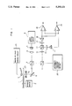
- FIG. 1 shows an arrangement of a magneto-optic disk device showing one embodiment of the magneto-optic recording/reproducing method according to the present invention
- FIG. 2 is a sectional view of one embodiment of a magneto-optic disk used in the above embodiment of FIG. 1;
- FIGS. 3, 8 and 9 are schematic diagrams showing isotherms during recording
- FIG. 4 is a view showing the shape of recorded magnetized domains in the embodiment of FIG. 1;
- FIG. 5 is a sectional view of a second embodiment of a magneto-optic disk according to the present invention.
- FIG. 6 is a sectional view of a third embodiment of a magneto-optic disk according to the present invention.
- FIG. 7 is a view showing a magnetized domain shape
- FIGS. 10(a) and 10(b) are graphs showing the relation between the magnetized domains and the reproduced signals.
- the shape of the recorded magnetized domain 102 is a feather which is asymmetrical from front to rear. This is because the temperature distribution in the vertically magnetized film at the moment when the application direction of a recording magnetic field is reversed is reflected in the recording shape of the magnetized domain.
- the temperature distribution of the vertically magnetized film depends a balance of the thermal conductivity and the beam speed in the vertically magnetized film.
- two forked angular projections 103 at the rear of the feather shape will be extended as the scanning speed of the laser beam is increased during the recording. If the angular projections 103 of the magnetized domain 102 are long, the signal amplitude will be reduced during the high density recording and also jitter will be produced during the recording/reproduction.
- the thermal conduction speed in the vertically magnetized film is sufficiently larger than the scanning speed.
- the temperature distribution 50 in the vertically magnetized film in the neighborhood of the area irradiated with the laser beam is substantially isotropic as shown in FIG. 8 so that the edge shape of the magnetized domain is semi-circular. Therefore, if the width of the magnetized domain is set to about 0.8 to 1 ⁇ m, the length of the angular projections may also be 0.4 to 0.5 ⁇ m.
- the signal band width required for reproduction is narrow and so the detection is hardly subjected to random noise so that the recording/reproduction with the bit pitch of about 0.5 ⁇ m can be carried out using the laser beam spot having a diameter of about 1.6 ⁇ m.
- the temperature distribution 50' in the vertically magnetized film is a shape having a trail left on the opposite side to the moving direction of the laser beam spot as shown in FIG. 9 so that the edge shape of the magnetized domain is parabolic.
- the width of the magnetized domain is set to about 0.8 to 1 ⁇ m, the length of the angular projections will be as large as 0.6 ⁇ m or more. In this case, the edge interval longer by 0.2 ⁇ m or more is required so that a recordable/reproducible bit pitch is 0.7 ⁇ m or more.
- the length of the angular projections will be short if the width of the magnetized domain to be recorded, the reproduced signal/noise ratio required for data demodulation can not be assured.
- the scanning speed of the laser beam is 7 m/sec or more, the attainable bit pitch will be 0.7 ⁇ m or more. Accordingly, it has been conventionally considered to be impossible to satisfy both the conditions of the bit pitch of 0.7 ⁇ m or less and the data transfer speed of 10M bit or more/sec since the length of the angular projections of the magnetized domain will be extended as the scanning speed is increased.
- the temperature distribution of the vertically magnetized film also depends on the change of the power and focal point of the laser beam and the difference in the recording medium characteristic so that the position and shape of the magnetic domains will be changed. This gives rise to incomplete erasure of the recorded magnetized domains during overwrite, and jitter during recording/reproduction.
- the magnetic field modulation technique is to be applied to a magneto-optic recording/reproducing device, it is important to suppress the extension of the angular projections 103 of the recorded magnetized domains 102 and enhancement of incomplete erasure.
- the present invention adopts an arrangement that, as shown in FIG. 4, the width of the magnetized domains 102' which effectively contribute to information reproduction is limited by the width of a land portion 104 which is a recording track.
- structure bands 112 which do not contribute to the read-out (reproduction) of magnetized domains are arranged on both sides of the land portion 104 which is a recording track.
- the magnetized domains 102 are recorded in accordance with the direction of the applied magnetic field over the area larger than the width w of the recording track 104.
- the width of the magnetized domains effectively contributing to information reproduction is limited to the width w of the recording track 104 by the structure bands 112 so that the magnetization state of the magnetized domains is read out only from the limited area 102' through the magneto-optic effect.
- This limitation of the width w of the magnetized domains permits the magnetized domain 102' having a constant width to be provided, and permits the reproduction to be freed from the influence of the two forked angular projections 103 at the rear of the feather shaped magnetized domains 102 formed by the recording while assuring the reproduced signal/noise ratio required for data demodulation.
- FIGS. 10(a) and 10(b) the relation among the width w of magnetized domains, light beam spots 201 for recording/reproduction, reproduced signals 202, and detection levels 203 are shown in FIGS. 10(a) and 10(b). If the relation between the magnetized domain width w and the length L of the angular projections is L>w/2 as shown in FIG. 10(a), the portion of the reproduced signal 202 corresponding to two closely adjacent edges can not be accurately demodulated since the signal 202 does not fall below the detection level 203 due to the influence of such long angular projections. On the other hand, if the width (the shaded portion in FIG.
- the edge position of a magnetized domain 102' has a one-to-one correspondence to a detection timing edge 204 resulted by slicing the reproduced signal 202 by the detection level 203, which permits accurate data demodulation at a high speed high density recording of the laser beam scanning speed of 7 m/sec or more.
- FIG. 1 shows an arrangement of a magneto-optic disk device showing one embodiment of the magneto-optic recording/reproducing method according to the present invention
- FIG. 2 is a sectional view of one embodiment of a magneto-optic disk used in the above embodiment of FIG. 1
- FIG. 3 is a schematic view showing the temperature distribution in the neighborhood of a laser beam spot during recording in the embodiment of FIG. 1
- FIG. 4 is a view showing the shape of a recorded magnetized domain in the embodiment of FIG. 1.
- FIG. 1 shows an arrangement of the magneto-optic disk device using one light beam.
- a disk 1 which is a recording medium is a magneto-optic disk having a vertically magnetized film mainly consisting of e.g. a Tb-Fe-Co compound.
- the section of the disk 1 is shown in FIG. 2.
- 106 is a substrate which is made of glass or transparent resin (e.g. polycarbonate, polystyrene, acrylic, ultraviolet setting resin, etc.).
- 107 is a vertically magnetized film which is a magneto-optic recording film of a rare earth transition metal system (e.g. or Tb-Fe-Co compound, a Tb-Fe compound, a Cd-Fe-Co compound, etc.).
- the vertically magnetized film 107 is deposited uniformly and continuously on substantially, i.e. virtually, the entire surface of the substrate 106.
- 108 is a light shading band for forming structure bands 112 which shade the vertically magnetized film 107 from a laser beam 111 irradiated through the substrate 106.
- the light shading band 108 may be a metallic thin film made of e.g. molybdenum, aluminum, etc.
- the substrate 106 may be reinforced glass having an outer periphery of ⁇ 130 mm and a thickness of about 1 mm.
- Formed on the substrate 106 through the vacuum evaporation technique is a metallic aluminum layer several hundred ⁇ or so thick in order to form the light shading bands 108 and also serving as a guide groove for tracking in a push-pull manner.
- a positive type photo resist is spin-coated on the entire surface to form a photoresist layer on the metallic aluminum layer.
- This photoresist layer is exposed to light and developed using a projection mask aligner to form a spiral mask (having a line width of 0.8 ⁇ m) with a pitch of 1.6 ⁇ m.
- the portion of the metallic aluminum layer which is not masked is etched away to provide the light shading band 108 of a spiral shape having a line width of 0.8 ⁇ m at a pitch of 1.6 ⁇ m.
- a protection film 121 made of SiN having a thickness of 700 ⁇ and having a Kerr enhancement effect, the vertically magnetized film 107 made of Tb-Fe-Co having a thickness of 1000 ⁇ , and a protection film 122 made of SiN having a thickness of 1500 ⁇ are successively formed through the sputtering technique.
- a protection coating 123 having a thickness of about 5 ⁇ m is formed in order to improve the sliding movement resistance of the disk.
- This protection coating 123 can be formed by irradiating the spin-coated ultraviolet setting resin with ultraviolet rays.
- the magneto-optic disk 1 is adapted to be rotatable by a spindle motor 2.
- Data recording on the magneto-optic disk 1 is carried out as follows.
- a semiconductor laser 3 is caused to emit light with a high power by a laser driving circuit 4.
- the laser driving circuit 4 in response to an instruction from a recording/reproducing control system (not shown), causes the semiconductor laser 3 to emit the light with a low power during the data reproducing and with a high power during the data recording to heat the recording film to its Curie temperature, at which the magnetization of the recording film can be reversed, through the magnetic field produced from a magnetic head 5.
- the laser driving circuit 4 may be a circuit used in the conventional write-once type optical disk device.
- the light beam emitted from the semiconductor laser 3 is changed to a parallel light by a lens 6.
- the parallel light, passing through a beam splitter 7, is reflected in a vertical direction by a galvanomirror 8, and converged as a minute spot on the recording film 107 of the disk 1 by a convergence lens 9 through the disk substrate 106.
- the wavelength of the laser beam emitted from the semiconductor laser 3 is 830 nm and the numerical aperture of the convergence lens 9 is 0.53
- the diameter at the spot periphery (hereinafter referred to as the light spot diameter) with a light intensity e -2 times as high as that at the spot center is about 1.6 ⁇ m.
- the track pitch of about 1.6 ⁇ m is suitable in view of the separation degree of tracks and the modulation degree of the tracking signal in a push-pull manner.
- the S/N of a magneto-optic signal is not so high so that the width of magnetized domains is desired to be large to provide a high signal modulation degree.
- the width of the land portion 104 of the disk 1 is set to 0.8 ⁇ m in accordance with a suitable width of the magnetized domains.
- the laser beam spot having a diameter of 1.6 ⁇ m travels along the center of the land portion 104, i.e., the center of the recording track.
- the intensity of the recording laser light beam is set in accordance with the scanning speed (line speed) of the laser light beam so that as shown in FIG. 3 the width w' of the area (shaded portion) surrounded by the isotherm in the neighborhood of the Curie temperature Tc in the temperature distribution of the area irradiated with the laser light beam 111 is larger than the width w of the recording track (land portion), e.g. 1 to 1.6 ⁇ m.
- the width w' of the area surrounded by the isotherm of the Curie temperature Tc is 1.3 ⁇ m.
- the modulated magnetic field in accordance with the data to be recorded is applied from the magnetic head 5 to perform data recording, i.e. to form magnetized domains.
- the area which is applied with the magnetic field from the magnetic head 5 is larger than the area irradiated with the laser beam spot so as to cover it so that the recorded magnetized domains reside in the area surrounded by the isotherm of Tc.
- the temperature of the vertically magnetized film 107 is enhanced to the Curie temperature Tc or more over the width w', e.g. 1.3 ⁇ m, so that the overwrite of data, i.e. recording which also serves to erase the previously recorded data, can be realized over the entire width w (e.g. 0.8 ⁇ m) of the land portion.
- the magnetic head 5 is arranged so as to slightly float above the surface of the disk 1. The distance between the magnetic head 1 and the disk may be several tens of ⁇ m.
- the magnetic head driving circuit 10 has a function of changing the direction of the magnetic field produced from the magnetic head 5 and its construction may be the same as the circuit used in the conventional magnetic disk device.
- the laser driving circuit 4 in response to an instruction from the recording/reproducing control system (not shown), causes the semiconductor laser 3 to emit the light with a low power.
- the light emitted from the semiconductor laser 3 has a polarization plane in a certain direction. This light, passing through the same light path as in the recording, is irradiated to the vertically magnetized film 107 on the disk 1.
- the part that participates in the reproduction is only the land portion 104 having a width w' (e.g. 0.8 ⁇ m) which is in the neighborhood of the center of the magnetized domains 102 recorded with a width w (e.g. 1.3 ⁇ m). Therefore, as shown in FIG.
- the width of the magnetic domains 102' which effectively contribute to the recording/reproducing is limited by the width of the land portion 104 to be 0.8 ⁇ m, so that the length of the angular projections can be limited to be less than 0.4 ⁇ m. Further, even if incomplete erasure due to incomplete overwrite is present on both sides of the magnetized domains 102 having a width of 1.3 ⁇ m, it can be effectively separated from the reproduction because of the presence of the structure bands 112 constructed by the light shading bands 108. Thus, the overwrite operation which is theoretically free from the incomplete erasure can be obtained.
- the magnetization direction of the recorded magnetized domains is fixed in an upward or downward direction in accordance with the recorded data.
- the Kerr effect means that the polarization plane of a reflected light rotates left or right with respect to an incident polarization plane in accordance with the magnetization direction of an upward or downward direction.
- the reflected light beam from the vertically magnetized film 107 which experiences the polarization plane rotation is reflected beam splitters 7 and 11 again and guided to a 1/2 wavelength plate 12.
- the 1/2 wavelength plate 12 is an optical device which serves to rotate the polarization plane by 45°.
- the light with its polarization plane rotated by 45° is separated into a p polarized-light component and an s polarized-light component, which are orthogonal to each other, by a polarized-light beam splitter 13. Both components are converged onto photodetectors 14 and 15, and 17 through lenses 16 respectively. Taking a sum of the outputs from the photodetectors 16 and 17 provides only the variation of the light intensity irrespective of the rotation of the polarization plane.
- the sum signal 18 which represents only prepits previously formed on the disk 1
- the difference signal 19 which represents only the change of the magnetization direction of the vertically magnetized film on the disk 1 i.e., the recorded data (magnetized domains)
- the light beam passing through the beam splitter 11 enters an automatic focussing and tracking control system 26 and is used to detect a focusing point deviation signal and a tracking deviation signal. By driving e.g. an actuator 23 by these signals, automatic focusing adjustment and tracking control are carried out.
- the disk 1 in the case where the disk 1 is rotated at a high speed and the scanning speed (linear speed) of the laser light beam is as high as 7 m/sec, it is possible to prevent the angular projections of the magnetized domains from being extended. Thus, it is possible to accurately carry out the data recording/reproducing at a high speed and with a high density without deteriorating the SIN due to incomplete erasure after repeated overwrites.
- FIG. 5 is a sectional view of a second embodiment of the magneto-optic recording medium used in the present invention.
- the land portion 104 and the structure band 112 are formed by depositing the magnetized film having a width of e.g. 0.8 ⁇ m, on the substrate 106 at a track pitch of 1.6 ⁇ m in a spiral or concentric circle shape.
- a protection coating 123 is also formed in order to improve the sliding movement resistance.
- the magnetized domains 102 are formed on only the vertically magnetized film 107 constituting the land portion (recording track) 104, if the magnetized domains 102 are recorded so that the width of the area heated to the Curie temperature Tc or more during the recording is larger than the width of the land portion 104, the width of the recorded magnetized domains 102 is limited by the width of the land portion 104.
- FIG. 6 is a sectional view of a third embodiment of the magneto-optic recording medium used in the present invention.
- a low thermal conductivity material layer 109 is formed in a strip shape on the substrate 106 and thereafter the vertically magnetized film 107 having a certain thickness and another low thermal conductivity material layer 109' made of e.g. SiO 2 are successive deposited through the sputtering technique.
- the vertically magnetized film 107 is made of a compound of a rare earth transition metal system (e.g.
- the vertically magnetized film 107 having a certain thickness and the low thermal conductivity material layer 109' made of SiO 2 may be successively formed through the sputtering technique (since the thermal conductivity of the substrate 106 is lower than that of the vertically magnetized film 107 by one order of magnitude or more).
- the protection coating 123 is formed in order to improve the sliding movement resistance.
- the magnetized domains are not extended over the land portion 104 since the land portion 104 and structure band 112 are thermally separated from each other by the low thermal conductivity material layers 109 and 109'. Therefore, if the magnetized domains 102 are recorded with the light intensity by which the temperature at the boundary between the land portion 104 and the structure band 112 exceeds the Curie temperature, the width of the recorded magnetized domains is limited by the width w of the land portion (recording track) 104.
- the temperature of the vertically magnetized film 107 on the land portion (recording track) 104 can be easily enhanced during the recording due to the adiabatic effect on both sides of the land portion (recording track) 104 so that the recording sensitivity is improved, which is very advantageous for high speed recording.
- the width of the magnetized domains 102' effectively contributing to data reproduction can be defined by the width of the land portion 104 that is a recording track.
- the present invention can be also applied to other systems, e.g. the optical modulation as disclosed in JP-A-62-175948.
- the problems of teardrop shape domains, thermal interference among domains, etc. occur due to the influence from the thermal conduction in the vertically magnetized film a s disclosed in the Proceedings of the International Symposium on Optical Memory, JJAP, Vol. 26 (1987), Supplement 26-4, p. 243 to 248.
- the width and length of domains must be simultaneously controlled, in accordance with the present invention, only the domain length has to be controlled, thereby making easy the high density recording. Incomplete erasure can be prevented in the overwrite using a single beam.
- the tracking margin as well as the erasure characteristic in the overwrite can be improved.
- a magneto-optic recording/reproducing method which, irrespective of the kind of a recording/reproducing device or a vertically magnetized film, can provide high medium compatibility and overwrite with a high density at a high speed, and a magneto-optic recording medium. Also, the reproduced signal/noise due to incomplete erasure is not deteriorated in the overwrite using a single beam.
Applications Claiming Priority (2)
| Application Number | Priority Date | Filing Date | Title |
|---|---|---|---|
| JP63-21953 | 1988-02-03 | ||
| JP63021953A JP2839498B2 (ja) | 1988-02-03 | 1988-02-03 | 光ディスク媒体 |
Publications (1)
| Publication Number | Publication Date |
|---|---|
| US5295121A true US5295121A (en) | 1994-03-15 |
Family
ID=12069427
Family Applications (1)
| Application Number | Title | Priority Date | Filing Date |
|---|---|---|---|
| US07/304,203 Expired - Lifetime US5295121A (en) | 1988-02-03 | 1989-01-31 | Magneto-optic recording/reproducing method and device and magneto-optic recording medium used for them |
Country Status (3)
| Country | Link |
|---|---|
| US (1) | US5295121A (ja) |
| EP (1) | EP0327315B1 (ja) |
| JP (2) | JP2839498B2 (ja) |
Cited By (4)
| Publication number | Priority date | Publication date | Assignee | Title |
|---|---|---|---|---|
| US5644556A (en) * | 1993-01-11 | 1997-07-01 | Canon Kabushiki Kaisha | Magneto-optical disk having cellularly divided regions with alternating directions of magnetization and method of initializing direction of magnetization of magneto-optical disk prior to recording of information |
| US5781513A (en) * | 1995-02-27 | 1998-07-14 | Sharp Kabushiki Kaisha | Magnetic-field modulation recording method and device for preventing residual information from remaining after overwriting |
| US20050094547A1 (en) * | 2003-10-29 | 2005-05-05 | Hitachi Maxell, Ltd. | Master disk exposure apparatus and master disk exposure method |
| CN100395819C (zh) * | 2004-02-27 | 2008-06-18 | Tdk股份有限公司 | 磁记录再现装置及磁记录介质 |
Families Citing this family (5)
| Publication number | Priority date | Publication date | Assignee | Title |
|---|---|---|---|---|
| NL8900362A (nl) * | 1989-02-15 | 1990-09-03 | Philips Nv | Werkwijze en inrichting voor het inschrijven en uitlezen van een magneto-optische registratiedrager. |
| NL8902293A (nl) * | 1989-09-14 | 1991-04-02 | Philips Nv | Werkwijze en inrichting voor het inschrijven en uitlezen van een magneto-optische registratiedrager. |
| NL8902728A (nl) * | 1989-11-06 | 1991-06-03 | Philips Nv | Werkwijze en inrichting voor het inschrijven en uitlezen van een magneto-optische registratiedrager. |
| JP2636957B2 (ja) * | 1990-08-10 | 1997-08-06 | シャープ株式会社 | 磁気記録再生装置 |
| JPH08147695A (ja) * | 1994-11-17 | 1996-06-07 | Matsushita Electric Ind Co Ltd | 書換型光ディスクのデータ記録方法と記録再生装置 |
Citations (12)
| Publication number | Priority date | Publication date | Assignee | Title |
|---|---|---|---|---|
| US3510658A (en) * | 1967-11-06 | 1970-05-05 | Ibm | Light beam servoing system with memory element having wavelength-discrimi-nating guide and data tracks |
| US3696346A (en) * | 1971-08-30 | 1972-10-03 | Honeywell Inc | Beam addressed optical memory |
| US4176377A (en) * | 1977-11-10 | 1979-11-27 | Eastman Kodak Company | Video disc configuration |
| JPS56105344A (en) * | 1980-01-25 | 1981-08-21 | Fuji Photo Film Co Ltd | Photomagnetic recording medium |
| JPS5718247A (en) * | 1980-07-04 | 1982-01-30 | Toyo Ink Mfg Co | Manufacture of laminate |
| JPS5774852A (en) * | 1980-10-23 | 1982-05-11 | Sharp Corp | Magnetic optical storing element |
| US4516234A (en) * | 1981-06-24 | 1985-05-07 | Tdk Electronics Co., Ltd. | Optical recording system |
| US4566088A (en) * | 1982-10-14 | 1986-01-21 | Matsushita Electric Industrial Co., Ltd. | Optical and reversible recording and reproducing apparatus |
| JPS6295754A (ja) * | 1985-10-22 | 1987-05-02 | Nippon Sheet Glass Co Ltd | 光磁気記録媒体 |
| JPS62175948A (ja) * | 1985-06-11 | 1987-08-01 | Nippon Kogaku Kk <Nikon> | オーバーライト可能な光磁気記録方法、それに使用される光磁気記録装置及び光磁気記録媒体、並びに変調方法、変調装置及び光磁気記録媒体 |
| US4737947A (en) * | 1983-06-14 | 1988-04-12 | Canon Kabushiki Kaisha | Recording medium having optomagnetic recording layer and optical recording layer with guide tracks of specific reflectance |
| US5065377A (en) * | 1989-09-14 | 1991-11-12 | U.S. Philips Corporation | Method of and apparatus for writing and reading a magneto-optical record carrier with an information density greater than that corresponding to the size of the scanning spot |
Family Cites Families (3)
| Publication number | Priority date | Publication date | Assignee | Title |
|---|---|---|---|---|
| JPS57186247A (en) * | 1981-05-11 | 1982-11-16 | Fuji Xerox Co Ltd | Photomagnetic recording medium |
| JPS57186214A (en) * | 1981-05-11 | 1982-11-16 | Ricoh Co Ltd | Vertical thermomagnetic recording method |
| JPS595450A (ja) * | 1982-07-02 | 1984-01-12 | Ricoh Co Ltd | 光磁気記録媒体 |
-
1988
- 1988-02-03 JP JP63021953A patent/JP2839498B2/ja not_active Expired - Lifetime
-
1989
- 1989-01-31 US US07/304,203 patent/US5295121A/en not_active Expired - Lifetime
- 1989-01-31 EP EP89300934A patent/EP0327315B1/en not_active Expired - Lifetime
-
1998
- 1998-08-03 JP JP10218792A patent/JPH11134733A/ja active Pending
Patent Citations (12)
| Publication number | Priority date | Publication date | Assignee | Title |
|---|---|---|---|---|
| US3510658A (en) * | 1967-11-06 | 1970-05-05 | Ibm | Light beam servoing system with memory element having wavelength-discrimi-nating guide and data tracks |
| US3696346A (en) * | 1971-08-30 | 1972-10-03 | Honeywell Inc | Beam addressed optical memory |
| US4176377A (en) * | 1977-11-10 | 1979-11-27 | Eastman Kodak Company | Video disc configuration |
| JPS56105344A (en) * | 1980-01-25 | 1981-08-21 | Fuji Photo Film Co Ltd | Photomagnetic recording medium |
| JPS5718247A (en) * | 1980-07-04 | 1982-01-30 | Toyo Ink Mfg Co | Manufacture of laminate |
| JPS5774852A (en) * | 1980-10-23 | 1982-05-11 | Sharp Corp | Magnetic optical storing element |
| US4516234A (en) * | 1981-06-24 | 1985-05-07 | Tdk Electronics Co., Ltd. | Optical recording system |
| US4566088A (en) * | 1982-10-14 | 1986-01-21 | Matsushita Electric Industrial Co., Ltd. | Optical and reversible recording and reproducing apparatus |
| US4737947A (en) * | 1983-06-14 | 1988-04-12 | Canon Kabushiki Kaisha | Recording medium having optomagnetic recording layer and optical recording layer with guide tracks of specific reflectance |
| JPS62175948A (ja) * | 1985-06-11 | 1987-08-01 | Nippon Kogaku Kk <Nikon> | オーバーライト可能な光磁気記録方法、それに使用される光磁気記録装置及び光磁気記録媒体、並びに変調方法、変調装置及び光磁気記録媒体 |
| JPS6295754A (ja) * | 1985-10-22 | 1987-05-02 | Nippon Sheet Glass Co Ltd | 光磁気記録媒体 |
| US5065377A (en) * | 1989-09-14 | 1991-11-12 | U.S. Philips Corporation | Method of and apparatus for writing and reading a magneto-optical record carrier with an information density greater than that corresponding to the size of the scanning spot |
Non-Patent Citations (4)
| Title |
|---|
| Proc. Int. Symp. on Optical Memory, 1987 Japanese Journal of Applied Physics, vol. 26 (1987) Supplement 26 4. * |
| Proc. Int. Symp. on Optical Memory, 1987 Japanese Journal of Applied Physics, vol. 26 (1987) Supplement 26-4. |
| Technical Report at the Academic Society of Electronic, Information and Communication MR 87 37 (1987) pp. 13 to 20. * |
| Technical Report at the Academic Society of Electronic, Information and Communication MR 87-37 (1987) pp. 13 to 20. |
Cited By (4)
| Publication number | Priority date | Publication date | Assignee | Title |
|---|---|---|---|---|
| US5644556A (en) * | 1993-01-11 | 1997-07-01 | Canon Kabushiki Kaisha | Magneto-optical disk having cellularly divided regions with alternating directions of magnetization and method of initializing direction of magnetization of magneto-optical disk prior to recording of information |
| US5781513A (en) * | 1995-02-27 | 1998-07-14 | Sharp Kabushiki Kaisha | Magnetic-field modulation recording method and device for preventing residual information from remaining after overwriting |
| US20050094547A1 (en) * | 2003-10-29 | 2005-05-05 | Hitachi Maxell, Ltd. | Master disk exposure apparatus and master disk exposure method |
| CN100395819C (zh) * | 2004-02-27 | 2008-06-18 | Tdk股份有限公司 | 磁记录再现装置及磁记录介质 |
Also Published As
| Publication number | Publication date |
|---|---|
| JP2839498B2 (ja) | 1998-12-16 |
| EP0327315A2 (en) | 1989-08-09 |
| JPH01199344A (ja) | 1989-08-10 |
| EP0327315A3 (en) | 1990-12-12 |
| EP0327315B1 (en) | 1995-01-04 |
| JPH11134733A (ja) | 1999-05-21 |
Similar Documents
| Publication | Publication Date | Title |
|---|---|---|
| US5432774A (en) | Optical recording medium | |
| US5295121A (en) | Magneto-optic recording/reproducing method and device and magneto-optic recording medium used for them | |
| US5694379A (en) | Magneto-optical recording medium and recording apparatus therefor | |
| US5321672A (en) | Method of an apparatus for magneto-optically recording information by changing the position or shape or controlling the diameter of reversed domains | |
| JP3155636B2 (ja) | 光記録媒体及び光記録再生システム | |
| JP2822531B2 (ja) | 光磁気記録媒体及び光磁気記録・消去方法 | |
| US5818811A (en) | Information recording and reproducing method for recording information on and reproducing information from an optical recording medium including a land portion divided into a plurality of information tracks | |
| US5380573A (en) | Optical recording medium | |
| US4806952A (en) | Information recording apparatus for recording/reproducing information by irradiating an information recording medium with an energy beam | |
| EP0701251B1 (en) | Optical recording medium and method of recording and/or reproducing on the medium | |
| US6117511A (en) | Optical recording media | |
| Takahashi | Magnetic super resolution | |
| JP2807470B2 (ja) | 光メモリ素子 | |
| JPH1055579A (ja) | 光磁気記録再生方法 | |
| WO1998024089A1 (en) | Optical recording medium | |
| KR100191364B1 (ko) | 광 기록 매체 | |
| JPH0714170A (ja) | 光ディスク装置 | |
| JPH06236578A (ja) | 光ディスク | |
| KR100317766B1 (ko) | 고밀도정보기록재생방법 | |
| JPH08161788A (ja) | 光学装置 | |
| JP2770522B2 (ja) | 光学的情報の記録方法 | |
| JP2000057626A (ja) | 光記録媒体 | |
| JP2001319376A (ja) | 光記録媒体およびその光再生装置 | |
| JP2000057577A (ja) | 光記録媒体 | |
| JPH05342625A (ja) | 光記録装置 |
Legal Events
| Date | Code | Title | Description |
|---|---|---|---|
| AS | Assignment |
Owner name: HITACHI, LTD., A CORP. OF JAPAN, JAPAN Free format text: ASSIGNMENT OF ASSIGNORS INTEREST.;ASSIGNORS:SUKEDA, HIROFUMI;KATO, KEIZO;REEL/FRAME:005037/0479 Effective date: 19890124 |
|
| STCF | Information on status: patent grant |
Free format text: PATENTED CASE |
|
| FPAY | Fee payment |
Year of fee payment: 4 |
|
| FEPP | Fee payment procedure |
Free format text: PAYOR NUMBER ASSIGNED (ORIGINAL EVENT CODE: ASPN); ENTITY STATUS OF PATENT OWNER: LARGE ENTITY |
|
| FPAY | Fee payment |
Year of fee payment: 8 |
|
| FPAY | Fee payment |
Year of fee payment: 12 |