US5282347A - Wrapping apparatus - Google Patents
Wrapping apparatus Download PDFInfo
- Publication number
- US5282347A US5282347A US07/942,067 US94206792A US5282347A US 5282347 A US5282347 A US 5282347A US 94206792 A US94206792 A US 94206792A US 5282347 A US5282347 A US 5282347A
- Authority
- US
- United States
- Prior art keywords
- track
- rollers
- shuttle
- wrapping
- wrapping apparatus
- Prior art date
- Legal status (The legal status is an assumption and is not a legal conclusion. Google has not performed a legal analysis and makes no representation as to the accuracy of the status listed.)
- Expired - Lifetime
Links
Images


Classifications
-
- B—PERFORMING OPERATIONS; TRANSPORTING
- B65—CONVEYING; PACKING; STORING; HANDLING THIN OR FILAMENTARY MATERIAL
- B65B—MACHINES, APPARATUS OR DEVICES FOR, OR METHODS OF, PACKAGING ARTICLES OR MATERIALS; UNPACKING
- B65B11/00—Wrapping, e.g. partially or wholly enclosing, articles or quantities of material, in strips, sheets or blanks, of flexible material
- B65B11/04—Wrapping, e.g. partially or wholly enclosing, articles or quantities of material, in strips, sheets or blanks, of flexible material the articles being rotated
-
- B—PERFORMING OPERATIONS; TRANSPORTING
- B65—CONVEYING; PACKING; STORING; HANDLING THIN OR FILAMENTARY MATERIAL
- B65B—MACHINES, APPARATUS OR DEVICES FOR, OR METHODS OF, PACKAGING ARTICLES OR MATERIALS; UNPACKING
- B65B25/00—Packaging other articles presenting special problems
- B65B25/24—Packaging annular articles, e.g. tyres
Definitions
- This invention relates to the packaging of goods, being an article or a bundle of articles, for their protection against corrosion or soiling by liquid or particulate contaminants during handling, transporting and storage operations.
- the invention was developed for the protective packaging of coils of steel strip and is described primarily with regard to that application hereinafter. It will be appreciated however that it is generally applicable to wrapping other goods in the nature of relatively large solid items.
- One class of known apparatus for applying a pliable wrapping medium has comprised a turntable or the like on which the article is placed and a draw-off spool holder rotatably supporting a spool of the wrapping medium.
- the spool holder includes tension regulating devices to maintain a suitable tension in the drawn-off medium and, in the case of stretch wrap film, to stretch it as it leaves the spool.
- the spool-holder (or the turntable) may be moved in the axial direction of the spool to cause successive turns of the wrapping medium applied to the article to overlap and so provide an uninterrupted coverage.
- the article has to be reoriented on the turntable at least once during the wrapping to obtain full coverage. Alternatively, if the shape of the article permits, it may be continuously reoriented on the turntable as wrapping proceeds.
- Another class of known apparatus which alleviates the last mentioned disadvantage provides a rotatable frame which supports the spool holder so that it may orbit about the article being wrapped.
- the article may be stationary except for such intermittent or continuous reorientation as may be needed for full coverage.
- a cylindrical article may be supported on two spaced apart parallel rollers with their axes horizontal. At least one of those support rollers may be driven to cause the article to turn slowly about its own, also horizontal, axis.
- the spool holder may be set to orbit the article in a generally horizontal plane, but which may be raised or lowered, with the spool axis vertical.
- the drawn-off medium will cover the whole of the article or will leave uncovered a central circular area of greater or lesser diameter of each end face of the article.
- the cylindrical article is also annular, for example a coil of metal strip, those uncovered areas may be adjusted to substantially coincide with the ends of the bore of the coil.
- Another class of known wrapping apparatus particularly suited to wrapping elongate articles comprises a circular structure which carries a spool holder. That structure is caused to rotate about its own axis, which is horizontal, to produce orbital movement of the spool holder about that axis. The article to be wrapped is passed by appropriate conveyors through the structure along that axis.
- the known art is quite well adapted for the external wrapping of reasonably compact or elongated articles, but is less well able to wrap oddly shaped articles.
- it does not permit the wrapping of large annular cylindrical articles, such as coils of metal strip, in a manner which covers not only the external surfaces but also the internal or bore surface, and an object of the present invention is to provide apparatus which may do that if desired.
- the invention achieves that object by providing a wrapping apparatus wherein the spool holder is mounted on a shuttle able to ride around an endless, stationary track on a loop structure having a gate portion which may be opened, that is to say temporarily swung aside or detached from the remainder of the loop structure, to permit an annular article to be linked with the track.
- the invention consists in a wrapping apparatus comprising a loop structure defining an endless track, a shuttle able to ride around said track, dispensing means on said shuttle able to hold a coil of a pliable wrapping medium and enabling medium to be drawn from the coil, and work piece support means able to support an article to be wrapped with at least a part of the article surrounded by said track; said loop structure including a gate portion that may be opened to produce a gap in said track and then closed, whereby an annular article may be linked with said track.
- a coil of wrapping medium is loaded into the dispensing means.
- An article is positioned on the support means so that it, or at least that part of it that is to be wrapped, as the case may be, is within the ambit of the track. If need be the gate portion is opened to allow the article to be put in place, and then reclosed. An end of the wrapping medium may then be secured to the article and the shuttle set in motion so that it orbits the article or the relevant part thereof. In this way the wrapping medium is drawn from the shuttle and applied to the article.
- the article is positioned so that the path of the dispensing means extends through the opening in the article.
- a problem inherent in apparatus according to the invention which is not usually present in prior known apparatus wherein relative rotation between the article and the roll about a fixed axis is relied upon to draw wrapping medium from the roll, is the difficulty of maintaining a tight wrap if there is a "mismatch" between the shape of the article being wrapped and the path of the shuttle. Such a mismatch occurs if more wrapping medium is drawn from the shuttle during a part of its travel than is taken up by the article during an immediately following part of its travel.
- This problem may be met or alleviated by appropriate shaping of the shuttle path if the article to be wrapped does not change, but is likely to arise during the operation of general purpose apparatus intended to be used for wrapping a variety of articles.
- preferred embodiments of the invention further comprise take-up accumulator means on the shuttle, which means are able to accommodate, and maintain tension in, a variable quantity of drawn off medium prior to its application to the article.
- the take-up accumulator means comprise a plurality of fixedly positioned training rollers, a plurality of yieldably positioned training rollers and loading means resiliently loading the yieldably positioned rollers away from the fixedly positioned rollers, so as to maintain tension in a variable length of wrapping media extending in a tortuous path about the respective rollers.
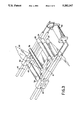
- FIG. 1 is a side elevation of a wrapping apparatus according to the invention.
- FIG. 2 is a diagrammatic longitudinal section through a shuttle, being a component of the apparatus of FIG. 1.
- FIG. 3 is a diagrammatic perspective view of take-up accumulator means, being components of the shuttle of FIG. 2.
- FIG. 4 is a diagrammatic perspective view of some internal parts of the shuttle of FIG. 2, showing more particularly its track wheels and electrical pick-up arrangements.
- the illustrated embodiment of the invention comprises a free standing support structure comprising a fabricated or cast metal column 5 extending rigidly upwardly from a floor mounting base 6. It supports a rigid loop structure comprising two spaced apart, co-directed cantilever beams 7 and 8 projecting from the column 5 and positioned one above the other in a common vertical plane and a gate portion 9 hinged at 10 one end to the free end of the upper beam 7 and extending, in its closed position, to the free end of the lower beam 8.
- the beams 7 and 8 and the gate portion 9 are preferably fabricated from steel plate and may comprise webs 16, inner edge flanges 17 and, in the case of beam 7, an outer edge flange 18.
- the loop structure as a whole may be raised or lowered as needed, by any conventional elevating mechanism associated with the column 5.
- it may be slideably mounted on the column and engaged by motor driven nuts threaded upon a screwed post within the column.
- the nuts may be fixed and the post rotatable, or an hydraulic or other thrustor may act directly on the loop structure.
- the gate portion 9 is a smoothly curved C shaped body and the junction between the bottom surface of the upper beam 7 and the upper surface of the lower beam 8 adjacent the column 5 is similarly smoothly curved.
- the beams 7 and 8 and the gate portion 9 when in the closed position, constitute an elongated rigid loop structure projecting from the column. That loop structure lies in a vertical plane with its long dimension substantially horizontal, it is spaced above the floor, preferably to an adjustable extent, and the opening 11 defined by it has a straight lower side and smoothly curved upper side and ends.
- the axis of the gate portion hinge 10 extends transversely of the loop structure so that the gate portion 9 may be swung upwardly from a closed position (shown in full line in FIG. 1), wherein its two ends respectively register with the free ends of the beams 7 and 8, to an open position (shown in broken line), wherein it is substantially clear of the beams.
- the ends of the gate portion 9 and the free ends of the beam 7 and 8 may be furnished with tapered inter-engaging formations or the like to ensure an accurate register therebetween.
- the gate portion 9 may be swung as aforesaid by means of a hydraulic or pneumatic cylinder 12 extending from a pivot connection 13 on the upper beam across the hinge axis to a pivot connection 14 on the gate portion 9.
- Those pivot connections are on pedestals so that the line of action of the cylinder 12 is spaced above the hinge axis 10.
- a shuttle 15 is provided which may ride around the inner periphery of the loop structure on a guide track formed, in this instance the guide track may be seen as a T-sectioned rail formed by the inner flanges 17 and the adjacent margin of the webs 16 of the beams 7 and 8 and the gate portion 9.
- the shuttle 15 comprises two rigidly spaced apart side plates 19 on and between which are rotatably mounted two pairs of inner track wheels 20, two pairs of outer track wheels 21 and two pairs of side track wheels 22.
- Those wheels may be moulded plastics wheels mounted for free rolling, in the case of the inner and outer wheels, on axles extending from one side plate 19 to the other and, in the case of the side track wheels, on brackets attached to the respective side plates. It will be clear to the skilled reader that the track wheels as a whole retain the shuttle to the head flange of the T-sectioned guide track while permitting it to ride therealong.
- the shuttle 15 is self-propelled by an electric motor 23 mounted on one side plate 19 and drive connected by conventional means (not shown) to a pinion 24 fixed to a rotatable one of the inner track wheel axles and engaged with a rack 48 on, and extending for the full lengths of, the flanges 17.
- the motor 23 may be energised by way of wiper contacts on the shuttle contacting rigid electric supply conductors mounted on, and extending for the full lengths of, the inner margins of the webs 16.
- wiper contacts and conductors are conventional items that are commercially available. They comprise conductor rails housed deep within insulating channels 25 and coacting sets of shoes 26 adapted to enter the mouths of the channels to make sliding contact with the rails.
- the shoes 26 are resiliently mounted on insulated conducting arms 27 rigidly mounted on a shuttle side plate 19. Two sets of shoes 26 are provided in respect of each rail to maintain continuity of supply as the shuttle travels across the junctions between the gate portion 9 and the beams 7 and 8.
- the supply to the conductor rails on the gate portion 9 may be maintained by contact at the beam ends when the gate portion is in the closed position, but for preference the supply is maintained by flexible conductors spanning the hinge.
- the shuttle 15 further comprises a mandrel or other spool holder 28 for a roll 29 of pliable wrapping medium, for example stretch plastic wrapping film, from which film 30 may be drawn, six fixedly positioned training rollers 31 to 36 respectively, two pre-stretch rollers 37 and 38 respectively, and two yieldably positioned training rollers 39 and 40 respectively.
- pliable wrapping medium for example stretch plastic wrapping film
- the pre-stretch rollers 37 and 38 cooperate with the training rolls 31, 32 and 33 to effect initial stretching of the film 5 as it leaves the roll 29. Their curved surfaces are conditioned in known manner to provide a considerable degree of friction between those surfaces and the film 30. Furthermore prestretch roller 38 runs at a higher speed than roller 37 so that the film 30 is necessarily stretched as it passes around the rollers. They also provide a brake on the film enabling it to be kept in tension by the article being wrapped.
- the rollers 39 and 40 are resiliently loaded away from the rollers 33, 34 and 35 by loading means comprising, in this instance, so called rodless pneumatic cylinders 41 that are each vented at one end and connected at its other end to a pressurised air reservoir 42.
- the cylinders 41 are also conventional proprietary items. Essentially each comprises an elongate cylinder with an internal piston and an external saddle 43, both of which are slidable longitudinally of the cylinder. The piston and saddle are kept in register by strong interacting permanent magnets respectively fixedly associated with them. This enables the rollers 39 and 40 to move to and for with the saddles 43, as indicated by the arrows in FIG. 3, while maintaining a substantially constant tension in the variable quantity of the film 30 trained around them and the rollers 33, 34 and 35.
- the volume of the reservoir 42 is sufficient to ensure that the air pressure within the cylinders 41 does not vary greatly as the pistons therein move to and fro.
- the numbers and spacing of the rollers of the accumulator means may be different from that illustrated and the loading means may take other convenient form, for example springs or a capstan drum driven through a constant torque, slipping clutch.
- a work piece support means is provided at a lower level than the loop structure. That support means may be fixed in position but preferably it is in the nature of a trolley 44 able to run on floor rails 45 to enable it to be loaded with the work piece, for example a coil 46 of steel strip elsewhere, and then brought into position below the loop structure (as indicated in broken line in FIG. 1). If the support means are fixed in position, it is desirable for the loop structure to be movable horizontally. Thus, in the instance of apparatus along the lines of that illustrated, the column base 6 would be designed to run on rails corresponding to the rails 45.
- the work piece support means preferably have two power driven, spaced apart, horizontal rollers 47 for the support of the work piece 46.
- the gate portion 9 is moved to the open position, the coil 46 of metal strip or other annular article to be wrapped is then positioned on the work piece support rollers 47, and those means moved along the rails 45 so that the lower beam 8 extends through the bore of the coil 46, the gate portion 9 is then closed so that the shuttle track is linked with the work piece 46, that is to say a part of the endless track extends through the bore of the work piece 46.
- An end of film 30 may then be drawn from the shuttle 15 and taped or otherwise fixed to the work piece 46.
- the shuttle 15 is then set in motion to wrap a turn of film around the upper part of the work piece and the work piece support means rollers 47 are set going until successive overlapping turns of film cover the entire surface of the coil 46, including its inner bore surface.
- the invention may wrap annular articles as described above it is not limited to such use.
- the provision of a carriage mounted spool holder travelling around an endless, gated track permits the ready positioning of many articles so that they are surrounded by the carriage path and therefore able to be wrapped by the carriage following that path.
- the work piece support means may be adapted for the support of non-annular work pieces.
- elongated articles may be passed continuously through the track loop by appropriate conveyors of known kind.
- the gate portion is not necessarily hingedly moved or swung between its open and closed position. It may be moved translationally or bodily from one position to the other. Such translational movement may be in the plane of the remainder of the loop structure or transversely thereof.
- the gate portion is effectively the top part of a more upright loop structure than that illustrated. It is opened by being lifted from the lower part of the structure and closed by being lowered onto the lower part.
- a loop structure similar to that illustrated is provided, except that only the top part of the structure is raised and lowered by elevator means associated with a column corresponding to column 5.
- the work piece support means may comprise a circular array of axially radiating conical rollers for the support of a work piece such as coil 46 lying on one end and its rotation about its then vertical axis.
Landscapes
- Engineering & Computer Science (AREA)
- Mechanical Engineering (AREA)
- Basic Packing Technique (AREA)
- Packaging Of Special Articles (AREA)
- Auxiliary Devices For And Details Of Packaging Control (AREA)
- Packages (AREA)
- Control And Other Processes For Unpacking Of Materials (AREA)
- Load-Engaging Elements For Cranes (AREA)
Applications Claiming Priority (4)
| Application Number | Priority Date | Filing Date | Title |
|---|---|---|---|
| AUPK9726 | 1991-11-12 | ||
| AUPK972691 | 1991-11-27 | ||
| AUPL1886 | 1992-04-13 | ||
| AUPL188692 | 1992-04-13 |
Publications (1)
| Publication Number | Publication Date |
|---|---|
| US5282347A true US5282347A (en) | 1994-02-01 |
Family
ID=25644164
Family Applications (1)
| Application Number | Title | Priority Date | Filing Date |
|---|---|---|---|
| US07/942,067 Expired - Lifetime US5282347A (en) | 1991-11-12 | 1992-09-09 | Wrapping apparatus |
Country Status (15)
| Country | Link |
|---|---|
| US (1) | US5282347A (ko) |
| EP (1) | EP0544312B1 (ko) |
| JP (1) | JP2753671B2 (ko) |
| KR (1) | KR100238987B1 (ko) |
| CN (1) | CN1039109C (ko) |
| AT (1) | ATE134954T1 (ko) |
| BR (1) | BR9204578A (ko) |
| CA (1) | CA2083905C (ko) |
| DE (1) | DE69208828T2 (ko) |
| ES (1) | ES2084912T3 (ko) |
| IN (1) | IN179999B (ko) |
| MX (1) | MX9206873A (ko) |
| MY (1) | MY108281A (ko) |
| NZ (1) | NZ245225A (ko) |
| PH (1) | PH30322A (ko) |
Cited By (36)
| Publication number | Priority date | Publication date | Assignee | Title |
|---|---|---|---|---|
| US5501058A (en) * | 1993-08-31 | 1996-03-26 | Kawasaki Steel Corporation | Coil packing line equipped with independently reciprocating carriages |
| US5755083A (en) * | 1994-02-14 | 1998-05-26 | Bhp Steel, (Jla) Pty. Ltd. | Wrapping apparatus with shuttle change |
| US5775515A (en) * | 1996-05-06 | 1998-07-07 | Chadwick Engineering Limited | Method and apparatus for wrapping coils, and the wrapped product |
| US5829234A (en) * | 1996-08-23 | 1998-11-03 | Oy M. Haloila Ab | Device for winding a wrapping film around an article to be packaged |
| US5850726A (en) * | 1996-11-12 | 1998-12-22 | Lantech, Inc. | Wrapping apparatus and method |
| US6006498A (en) * | 1995-09-22 | 1999-12-28 | Bhp Steel (Jla) Pty. Ltd. | Wrapping apparatus including a shuttle orbital movement around an object to be wrapped and method using same |
| US6032436A (en) * | 1998-01-29 | 2000-03-07 | Herr-Voss Corporation | Wrapping apparatus and method |
| US6192653B1 (en) * | 1998-02-10 | 2001-02-27 | Illinois Tool Works Inc. | Packaging device |
| US6247294B1 (en) | 1998-12-11 | 2001-06-19 | Oy M. Haloila Ab | Wrapping apparatus |
| WO2001070575A1 (en) * | 2000-03-23 | 2001-09-27 | Intergrated Industrial Systems | Spool transfer coil wrapping machine |
| EP1253083A1 (en) | 2001-04-19 | 2002-10-30 | ITW Limited | Web tensioning device |
| US6520445B2 (en) * | 1999-12-06 | 2003-02-18 | Luiz Henrique Araujo | Coil wrapping machine |
| US20030200731A1 (en) * | 2002-04-30 | 2003-10-30 | Pesmel Oy | Wrapping device with a circular track structure, and a film feeding device |
| US20030200732A1 (en) * | 2002-04-30 | 2003-10-30 | Pesmel Oy | Film feeding device and an automatic wrapping device |
| US6688076B1 (en) * | 2002-05-30 | 2004-02-10 | Victor M. Rivera, Jr. | Apparatus for wrapping articles in film material |
| US6729106B2 (en) | 2001-06-15 | 2004-05-04 | Robert B. Wiley | Orbital pallet wrapping machine and method |
| US20040139696A1 (en) * | 2002-10-11 | 2004-07-22 | Corral Bradley R. | Production line banding system |
| US20050229545A1 (en) * | 2004-03-15 | 2005-10-20 | H. Bohl Gmbh | Method for wrapping a long or round part, for example a steel part |
| US20080168643A1 (en) * | 2007-01-12 | 2008-07-17 | Illinois Tool Works Inc. | Shuttle change system and method for wrapping apparatus |
| US20090158692A1 (en) * | 2006-05-10 | 2009-06-25 | Laensikallio Juha-Matti | Wrapping Device and Method for Operating a Wrapping Device |
| US20100257816A1 (en) * | 2009-04-14 | 2010-10-14 | Illinois Took Works Inc. | Film-tail sealing system and method for wrapping apparatus |
| US20110070405A1 (en) * | 2008-04-29 | 2011-03-24 | Newfrey Llc | Wrapping tape for a cable harness |
| US20110068234A1 (en) * | 2008-04-29 | 2011-03-24 | Newfrey Llc | Fastening element for a cable harness |
| US20110072763A1 (en) * | 2008-04-29 | 2011-03-31 | Newfrey Llc | Apparatus and method for automatically, circumferentially wrapping a cable harness |
| US20120180430A1 (en) * | 2011-01-14 | 2012-07-19 | Groupe Anderson Inc. | Wrapping machine and inline wrapper comprising the same |
| US20130055678A1 (en) * | 2010-03-15 | 2013-03-07 | Kna Corporation Oy | Coil Packaging System |
| US20170137250A1 (en) * | 2013-11-26 | 2017-05-18 | Kna Corporation Oy | Apparatus, method, and system for wrapping a wrapping material, a wrapping device, and a control unit |
| US20190279458A1 (en) * | 2018-03-07 | 2019-09-12 | The Hillman Group, Inc. | Automated packaging system for a self-service custom-fabrication kiosk |
| USD868860S1 (en) * | 2018-06-11 | 2019-12-03 | Baron Buehring | Side panel for high capacity dispensing unit |
| USD868859S1 (en) * | 2018-06-11 | 2019-12-03 | Baron Buehring | Side panel for high capacity dispensing unit |
| USD868858S1 (en) * | 2018-06-11 | 2019-12-03 | Baron Buehring | Side panel for high capacity dispensing unit |
| USD869527S1 (en) * | 2018-06-11 | 2019-12-10 | Baron Buehring | Side panel for high capacity dispensing unit |
| USD873317S1 (en) * | 2018-06-11 | 2020-01-21 | Baron Buehring | Side panel for high capacity dispensing unit |
| US10583945B2 (en) * | 2011-08-16 | 2020-03-10 | Prasmatic S.R.L. | Wrapping machine and wrapping method |
| CN114084399A (zh) * | 2021-12-02 | 2022-02-25 | 山东银宝轮胎集团有限公司 | 一种轮胎缠膜机 |
| US20220089305A1 (en) * | 2016-07-05 | 2022-03-24 | Taylor-Winfield Technologies, Inc. | Robotic strapping machine and method |
Families Citing this family (13)
| Publication number | Priority date | Publication date | Assignee | Title |
|---|---|---|---|---|
| WO1995012525A1 (en) * | 1993-11-05 | 1995-05-11 | Bhp Steel (Awi) Pty. Ltd. | Coil tying apparatus and method |
| BR9501848A (pt) * | 1995-04-28 | 1997-08-12 | Siderurgica Nacional Sa | Aperfeiçoamento em máquina para embalagem de bobinas de chapas metálicas |
| FI105666B (fi) | 1998-02-11 | 2000-09-29 | Haloila M Oy Ab | Käärintälaite |
| DE69937844D1 (de) * | 1999-01-29 | 2008-02-07 | Kohan Kogyo Co Ltd | Verpackungsvorrichtung |
| JP4546618B2 (ja) * | 2000-06-22 | 2010-09-15 | 新日本製鐵株式会社 | 梱包装置の運転方法 |
| FI113361B (fi) * | 2003-02-25 | 2004-04-15 | Octomeca Oy | Käärintäpakkauskone |
| CN101804872A (zh) * | 2010-03-09 | 2010-08-18 | 鞍山市弘鑫包装材料有限公司 | 钢卷包装用自动薄膜缠绕机 |
| CN102367076B (zh) | 2011-10-02 | 2013-11-06 | 上海宏曲电子科技有限公司 | 管状材料包装的挂式并推型排队装置 |
| NL2012215C2 (nl) * | 2014-02-06 | 2015-08-10 | Bandall Benelux B V | Inrichting voor het rond een product aanbrengen van een band flexibel materiaal. |
| CN106945860A (zh) * | 2017-05-19 | 2017-07-14 | 上海景林包装机械有限公司 | 一种用于环状物体包装的小车行走轨道装置 |
| CN110077671A (zh) * | 2019-04-30 | 2019-08-02 | 哈工大机器人智能制造有限公司 | 筒状产品外包装捆扎机构及方法 |
| CN112938068A (zh) * | 2021-03-09 | 2021-06-11 | 北京首钢国际工程技术有限公司 | 一种覆膜机机头 |
| CN116741531B (zh) * | 2023-08-14 | 2023-11-03 | 浙江炬源物联科技有限公司 | 一种互感器绝缘聚酯薄膜梭子自动缠绕设备及其缠绕工艺 |
Citations (16)
| Publication number | Priority date | Publication date | Assignee | Title |
|---|---|---|---|---|
| US3116032A (en) * | 1961-06-28 | 1963-12-31 | Package Machinery Co | Web feeding system |
| DE1244045B (de) * | 1964-04-10 | 1967-07-06 | Hans Boehl Maschinenfabrik | Einwickelmaschine fuer ringfoermige Gueter |
| US3348787A (en) * | 1966-05-20 | 1967-10-24 | Nu Roll Corp | Drive and drive control for supply rolls |
| US3486293A (en) * | 1966-01-05 | 1969-12-30 | Metaverpa Nv Maartensdijk | Apparatus for associating objects and wrapping material |
| FR2057524A5 (ko) * | 1969-08-25 | 1971-05-21 | Ural Z Tyazhelogo | |
| DE2256708A1 (de) * | 1972-11-18 | 1974-05-22 | Transporttechnik Gmbh | Umwicklungsmaschine |
| SU761374A1 (ru) * | 1978-07-10 | 1980-09-07 | Od Staleprokatnyj Z Im Dzerzhi | Устройство для упаковки кольцеобразных изделий 1 |
| AU7043681A (en) * | 1980-05-20 | 1981-11-26 | Patrick Rayfield Lancaster III | Rotating stretch wrap apparatus |
| GB2079730A (en) * | 1980-07-10 | 1982-01-27 | Baker Perkins Holdings Ltd | Tensioning web by clamping side face of wound web reel |
| EP0044627A1 (en) * | 1980-06-25 | 1982-01-27 | Encomech Product Development Limited | Apparatus for packaging coils of sheet or strip metal |
| AU7496981A (en) * | 1980-09-08 | 1982-03-18 | E.G. Rowe Pty Ltd | Orbital wrapper |
| SU982977A1 (ru) * | 1981-07-22 | 1982-12-23 | Одесское Сталепрокатное Производственное Объединение Им.Дзержинского | Устройство дл упаковки мотков проволоки |
| US4761934A (en) * | 1987-02-27 | 1988-08-09 | Lantech | Parallel belted clamp |
| SU1465347A1 (ru) * | 1987-04-13 | 1989-03-15 | Магнитогорский Метизно-Металлургический Завод | Устройство дл упаковывани кольцеобразных изделий |
| US4829753A (en) * | 1988-01-15 | 1989-05-16 | Bricmont Francis H | Apparatus for wrapping overlapping laps of strip material over a cylindrical object having an axial opening therein |
| EP0371892A1 (fr) * | 1988-12-01 | 1990-06-06 | Mabotex S.A. | Moyens d'ensachage de compresses pliées |
Family Cites Families (3)
| Publication number | Priority date | Publication date | Assignee | Title |
|---|---|---|---|---|
| JPS4887997A (ko) * | 1972-02-25 | 1973-11-19 | ||
| JPS50150597A (ko) * | 1974-05-27 | 1975-12-03 | ||
| JPS58183414A (ja) * | 1982-04-20 | 1983-10-26 | ストラパック株式会社 | 梱包装置 |
-
1992
- 1992-09-09 US US07/942,067 patent/US5282347A/en not_active Expired - Lifetime
- 1992-10-07 MY MYPI92001811A patent/MY108281A/en unknown
- 1992-10-09 PH PH45077A patent/PH30322A/en unknown
- 1992-11-23 NZ NZ245225A patent/NZ245225A/xx not_active IP Right Cessation
- 1992-11-24 JP JP4338015A patent/JP2753671B2/ja not_active Expired - Lifetime
- 1992-11-24 IN IN856CA1992D patent/IN179999B/en unknown
- 1992-11-26 CA CA002083905A patent/CA2083905C/en not_active Expired - Lifetime
- 1992-11-26 ES ES92120239T patent/ES2084912T3/es not_active Expired - Lifetime
- 1992-11-26 EP EP92120239A patent/EP0544312B1/en not_active Expired - Lifetime
- 1992-11-26 AT AT92120239T patent/ATE134954T1/de not_active IP Right Cessation
- 1992-11-26 BR BR9204578A patent/BR9204578A/pt not_active IP Right Cessation
- 1992-11-26 DE DE69208828T patent/DE69208828T2/de not_active Expired - Lifetime
- 1992-11-27 KR KR1019920022673A patent/KR100238987B1/ko not_active IP Right Cessation
- 1992-11-27 MX MX9206873A patent/MX9206873A/es unknown
- 1992-11-27 CN CN92112860A patent/CN1039109C/zh not_active Expired - Lifetime
Patent Citations (16)
| Publication number | Priority date | Publication date | Assignee | Title |
|---|---|---|---|---|
| US3116032A (en) * | 1961-06-28 | 1963-12-31 | Package Machinery Co | Web feeding system |
| DE1244045B (de) * | 1964-04-10 | 1967-07-06 | Hans Boehl Maschinenfabrik | Einwickelmaschine fuer ringfoermige Gueter |
| US3486293A (en) * | 1966-01-05 | 1969-12-30 | Metaverpa Nv Maartensdijk | Apparatus for associating objects and wrapping material |
| US3348787A (en) * | 1966-05-20 | 1967-10-24 | Nu Roll Corp | Drive and drive control for supply rolls |
| FR2057524A5 (ko) * | 1969-08-25 | 1971-05-21 | Ural Z Tyazhelogo | |
| DE2256708A1 (de) * | 1972-11-18 | 1974-05-22 | Transporttechnik Gmbh | Umwicklungsmaschine |
| SU761374A1 (ru) * | 1978-07-10 | 1980-09-07 | Od Staleprokatnyj Z Im Dzerzhi | Устройство для упаковки кольцеобразных изделий 1 |
| AU7043681A (en) * | 1980-05-20 | 1981-11-26 | Patrick Rayfield Lancaster III | Rotating stretch wrap apparatus |
| EP0044627A1 (en) * | 1980-06-25 | 1982-01-27 | Encomech Product Development Limited | Apparatus for packaging coils of sheet or strip metal |
| GB2079730A (en) * | 1980-07-10 | 1982-01-27 | Baker Perkins Holdings Ltd | Tensioning web by clamping side face of wound web reel |
| AU7496981A (en) * | 1980-09-08 | 1982-03-18 | E.G. Rowe Pty Ltd | Orbital wrapper |
| SU982977A1 (ru) * | 1981-07-22 | 1982-12-23 | Одесское Сталепрокатное Производственное Объединение Им.Дзержинского | Устройство дл упаковки мотков проволоки |
| US4761934A (en) * | 1987-02-27 | 1988-08-09 | Lantech | Parallel belted clamp |
| SU1465347A1 (ru) * | 1987-04-13 | 1989-03-15 | Магнитогорский Метизно-Металлургический Завод | Устройство дл упаковывани кольцеобразных изделий |
| US4829753A (en) * | 1988-01-15 | 1989-05-16 | Bricmont Francis H | Apparatus for wrapping overlapping laps of strip material over a cylindrical object having an axial opening therein |
| EP0371892A1 (fr) * | 1988-12-01 | 1990-06-06 | Mabotex S.A. | Moyens d'ensachage de compresses pliées |
Non-Patent Citations (3)
| Title |
|---|
| Derwent Abstract Accession No. 91 049006/07, class Q31, SU, A, 1570944 (Kaun Poly) Jun. 15, 1990. * |
| Derwent Abstract Accession No. 91-049006/07, class Q31, SU, A, 1570944 (Kaun Poly) Jun. 15, 1990. |
| Derwent Abstract Accession No. J4161Y/41, class Q31, SU, A, 545524 (Tbilisi Prodmash) Apr. 6, 1977. * |
Cited By (52)
| Publication number | Priority date | Publication date | Assignee | Title |
|---|---|---|---|---|
| US5501058A (en) * | 1993-08-31 | 1996-03-26 | Kawasaki Steel Corporation | Coil packing line equipped with independently reciprocating carriages |
| US5755083A (en) * | 1994-02-14 | 1998-05-26 | Bhp Steel, (Jla) Pty. Ltd. | Wrapping apparatus with shuttle change |
| US6006498A (en) * | 1995-09-22 | 1999-12-28 | Bhp Steel (Jla) Pty. Ltd. | Wrapping apparatus including a shuttle orbital movement around an object to be wrapped and method using same |
| US5775515A (en) * | 1996-05-06 | 1998-07-07 | Chadwick Engineering Limited | Method and apparatus for wrapping coils, and the wrapped product |
| US5829234A (en) * | 1996-08-23 | 1998-11-03 | Oy M. Haloila Ab | Device for winding a wrapping film around an article to be packaged |
| US5850726A (en) * | 1996-11-12 | 1998-12-22 | Lantech, Inc. | Wrapping apparatus and method |
| US6032436A (en) * | 1998-01-29 | 2000-03-07 | Herr-Voss Corporation | Wrapping apparatus and method |
| US6192653B1 (en) * | 1998-02-10 | 2001-02-27 | Illinois Tool Works Inc. | Packaging device |
| US6446418B1 (en) | 1998-02-10 | 2002-09-10 | Illinois Tool Works, Inc. | Packaging device |
| US6247294B1 (en) | 1998-12-11 | 2001-06-19 | Oy M. Haloila Ab | Wrapping apparatus |
| US6520445B2 (en) * | 1999-12-06 | 2003-02-18 | Luiz Henrique Araujo | Coil wrapping machine |
| WO2001070575A1 (en) * | 2000-03-23 | 2001-09-27 | Intergrated Industrial Systems | Spool transfer coil wrapping machine |
| US6324820B1 (en) | 2000-03-23 | 2001-12-04 | Intergrated Industrial Systems, Inc. | Spool transfer coil wrapping machine |
| EP1253083A1 (en) | 2001-04-19 | 2002-10-30 | ITW Limited | Web tensioning device |
| US6775961B2 (en) | 2001-04-19 | 2004-08-17 | Itw Ltd | Web tensioning device |
| US6729106B2 (en) | 2001-06-15 | 2004-05-04 | Robert B. Wiley | Orbital pallet wrapping machine and method |
| US20030200731A1 (en) * | 2002-04-30 | 2003-10-30 | Pesmel Oy | Wrapping device with a circular track structure, and a film feeding device |
| US20030200732A1 (en) * | 2002-04-30 | 2003-10-30 | Pesmel Oy | Film feeding device and an automatic wrapping device |
| US6851252B2 (en) | 2002-04-30 | 2005-02-08 | Pesmel Oy | Film feeding device and an automatic wrapping device |
| US6889488B2 (en) | 2002-04-30 | 2005-05-10 | Pesmel Oy | Wrapping device with a circular track structure, and a film feeding device |
| US6688076B1 (en) * | 2002-05-30 | 2004-02-10 | Victor M. Rivera, Jr. | Apparatus for wrapping articles in film material |
| US20040139696A1 (en) * | 2002-10-11 | 2004-07-22 | Corral Bradley R. | Production line banding system |
| US6941734B2 (en) * | 2002-10-11 | 2005-09-13 | Chs Acquisition Corp. | Production line banding system |
| US20050229545A1 (en) * | 2004-03-15 | 2005-10-20 | H. Bohl Gmbh | Method for wrapping a long or round part, for example a steel part |
| US7757463B2 (en) * | 2004-03-15 | 2010-07-20 | H. Bohl Gmbh | Method for helically wrapping a part |
| US20090158692A1 (en) * | 2006-05-10 | 2009-06-25 | Laensikallio Juha-Matti | Wrapping Device and Method for Operating a Wrapping Device |
| US7963087B2 (en) * | 2006-05-10 | 2011-06-21 | Kna Corporation Oy | Wrapping device and method for operating a wrapping device |
| US20080168643A1 (en) * | 2007-01-12 | 2008-07-17 | Illinois Tool Works Inc. | Shuttle change system and method for wrapping apparatus |
| US8037661B2 (en) * | 2007-01-12 | 2011-10-18 | Illinois Tool Works Inc. | Shuttle change system and method for wrapping apparatus |
| US8334045B2 (en) | 2008-04-29 | 2012-12-18 | Newfrey Llc | Wrapping tape for a cable harness |
| US20110070405A1 (en) * | 2008-04-29 | 2011-03-24 | Newfrey Llc | Wrapping tape for a cable harness |
| US20110068234A1 (en) * | 2008-04-29 | 2011-03-24 | Newfrey Llc | Fastening element for a cable harness |
| US20110072763A1 (en) * | 2008-04-29 | 2011-03-31 | Newfrey Llc | Apparatus and method for automatically, circumferentially wrapping a cable harness |
| US8146491B2 (en) * | 2008-04-29 | 2012-04-03 | Newfrey Llc | Apparatus and method for automatically, circumferentially wrapping a cable harness |
| US8210483B2 (en) | 2008-04-29 | 2012-07-03 | Newfrey Llc | Fastening element for a cable harness |
| US8650836B2 (en) * | 2009-04-14 | 2014-02-18 | Illinois Tool Works Inc. | Film-tail sealing system and method for wrapping apparatus |
| US20100257816A1 (en) * | 2009-04-14 | 2010-10-14 | Illinois Took Works Inc. | Film-tail sealing system and method for wrapping apparatus |
| US20130055678A1 (en) * | 2010-03-15 | 2013-03-07 | Kna Corporation Oy | Coil Packaging System |
| US20120180430A1 (en) * | 2011-01-14 | 2012-07-19 | Groupe Anderson Inc. | Wrapping machine and inline wrapper comprising the same |
| US10583945B2 (en) * | 2011-08-16 | 2020-03-10 | Prasmatic S.R.L. | Wrapping machine and wrapping method |
| US20170137250A1 (en) * | 2013-11-26 | 2017-05-18 | Kna Corporation Oy | Apparatus, method, and system for wrapping a wrapping material, a wrapping device, and a control unit |
| US11987407B2 (en) * | 2016-07-05 | 2024-05-21 | Taylor-Winfield Technologies, Inc. | Robotic strapping machine and method |
| US20220089305A1 (en) * | 2016-07-05 | 2022-03-24 | Taylor-Winfield Technologies, Inc. | Robotic strapping machine and method |
| US20190279458A1 (en) * | 2018-03-07 | 2019-09-12 | The Hillman Group, Inc. | Automated packaging system for a self-service custom-fabrication kiosk |
| US10854035B2 (en) * | 2018-03-07 | 2020-12-01 | The Hillman Group, Inc. | Automated packaging system for a self-service custom-fabrication kiosk |
| USD869527S1 (en) * | 2018-06-11 | 2019-12-10 | Baron Buehring | Side panel for high capacity dispensing unit |
| USD873317S1 (en) * | 2018-06-11 | 2020-01-21 | Baron Buehring | Side panel for high capacity dispensing unit |
| USD868858S1 (en) * | 2018-06-11 | 2019-12-03 | Baron Buehring | Side panel for high capacity dispensing unit |
| USD868859S1 (en) * | 2018-06-11 | 2019-12-03 | Baron Buehring | Side panel for high capacity dispensing unit |
| USD868860S1 (en) * | 2018-06-11 | 2019-12-03 | Baron Buehring | Side panel for high capacity dispensing unit |
| CN114084399A (zh) * | 2021-12-02 | 2022-02-25 | 山东银宝轮胎集团有限公司 | 一种轮胎缠膜机 |
| CN114084399B (zh) * | 2021-12-02 | 2023-02-14 | 山东银宝轮胎集团有限公司 | 一种轮胎缠膜机 |
Also Published As
| Publication number | Publication date |
|---|---|
| DE69208828T2 (de) | 1996-10-02 |
| KR100238987B1 (ko) | 2000-03-02 |
| CN1078701A (zh) | 1993-11-24 |
| IN179999B (ko) | 1998-01-03 |
| JPH05294314A (ja) | 1993-11-09 |
| PH30322A (en) | 1997-03-06 |
| ES2084912T3 (es) | 1996-05-16 |
| CA2083905A1 (en) | 1993-05-28 |
| CA2083905C (en) | 2003-04-15 |
| ATE134954T1 (de) | 1996-03-15 |
| EP0544312A1 (en) | 1993-06-02 |
| MY108281A (en) | 1996-09-30 |
| BR9204578A (pt) | 1993-06-01 |
| DE69208828D1 (de) | 1996-04-11 |
| EP0544312B1 (en) | 1996-03-06 |
| JP2753671B2 (ja) | 1998-05-20 |
| NZ245225A (en) | 1994-08-26 |
| MX9206873A (es) | 1993-05-01 |
| KR930009864A (ko) | 1993-06-21 |
| CN1039109C (zh) | 1998-07-15 |
Similar Documents
| Publication | Publication Date | Title |
|---|---|---|
| US5282347A (en) | Wrapping apparatus | |
| US5203139A (en) | Apparatus and method for winding and wrapping rolls of web material | |
| US4829753A (en) | Apparatus for wrapping overlapping laps of strip material over a cylindrical object having an axial opening therein | |
| US6688076B1 (en) | Apparatus for wrapping articles in film material | |
| US7540124B2 (en) | Apparatus and method for stretch wrapping a plurality of tubes | |
| US3599851A (en) | Hydrodynamic turnover mechanisms | |
| AU653255B2 (en) | Wrapping apparatus | |
| US3515327A (en) | Apparatus for storing a variable length of strip | |
| MXPA02003864A (es) | Dispositivo para aplicar tension a una membrana. | |
| JPH04371441A (ja) | 帯状部材の巻取装置 | |
| CN110479793A (zh) | 一种自动上卷和对中的开卷机成套设备 | |
| US4409777A (en) | Web threading apparatus | |
| CN117466040A (zh) | 一种应用卧式储料装置的涂布机及其工作方式 | |
| JPS598572B2 (ja) | 車両用の積卸装置 | |
| FI90504C (fi) | Nauhanohjain kelauslaitteita varten | |
| US5899657A (en) | Automated mechanical storage facility | |
| JP2002166906A (ja) | 包装装置およびこれに用いるハンドリング装置 | |
| CN211281582U (zh) | 一种钢卷绕膜机 | |
| CN113734512A (zh) | 一种轴承滚子包装系统及包装方法 | |
| US4511094A (en) | Winding apparatus | |
| JPH0368808B2 (ko) | ||
| CN117048909B (zh) | 一种用于全自动收管机的盘管取料称重机构 | |
| CN212046648U (zh) | 一种带有压纹装置的倒卷机 | |
| CN113335674B (zh) | 搓卷包装机 | |
| JPH0533482Y2 (ko) |
Legal Events
| Date | Code | Title | Description |
|---|---|---|---|
| AS | Assignment |
Owner name: K. C. METAL PRODUCTS PROPRIETARY LIMITED, AUSTRALI Free format text: ASSIGNMENT OF ASSIGNORS INTEREST.;ASSIGNORS:CLEINE, KENNETH DAVID;VENTURIN, JOHN GERARD;REEL/FRAME:006429/0719 Effective date: 19921022 Owner name: JOHN LYSAGHT (AUSTRALIA) LIMITED, AUSTRALIA Free format text: ASSIGNMENT OF ASSIGNORS INTEREST.;ASSIGNORS:CLEINE, KENNETH DAVID;VENTURIN, JOHN GERARD;REEL/FRAME:006429/0719 Effective date: 19921022 |
|
| STCF | Information on status: patent grant |
Free format text: PATENTED CASE |
|
| FEPP | Fee payment procedure |
Free format text: PAYOR NUMBER ASSIGNED (ORIGINAL EVENT CODE: ASPN); ENTITY STATUS OF PATENT OWNER: LARGE ENTITY |
|
| FPAY | Fee payment |
Year of fee payment: 4 |
|
| FEPP | Fee payment procedure |
Free format text: PAYOR NUMBER ASSIGNED (ORIGINAL EVENT CODE: ASPN); ENTITY STATUS OF PATENT OWNER: LARGE ENTITY Free format text: PAYER NUMBER DE-ASSIGNED (ORIGINAL EVENT CODE: RMPN); ENTITY STATUS OF PATENT OWNER: LARGE ENTITY |
|
| FPAY | Fee payment |
Year of fee payment: 8 |
|
| AS | Assignment |
Owner name: ITW LIMITED, UNITED KINGDOM Free format text: ASSIGNMENT OF ASSIGNORS INTEREST;ASSIGNOR:KC METAL PRODUCTS PTY. LTD.;REEL/FRAME:014446/0407 Effective date: 20030922 |
|
| AS | Assignment |
Owner name: ITW LIMITED, UNITED KINGDOM Free format text: ASSIGNMENT OF ASSIGNORS INTEREST;ASSIGNOR:KC METAL PRODUCTS PTY. LTD.;REEL/FRAME:014499/0261 Effective date: 20030922 |
|
| FPAY | Fee payment |
Year of fee payment: 12 |