US5223877A - Camera system - Google Patents
Camera system Download PDFInfo
- Publication number
- US5223877A US5223877A US07/656,223 US65622391A US5223877A US 5223877 A US5223877 A US 5223877A US 65622391 A US65622391 A US 65622391A US 5223877 A US5223877 A US 5223877A
- Authority
- US
- United States
- Prior art keywords
- lens
- camera body
- input
- camera system
- information processing
- Prior art date
- Legal status (The legal status is an assumption and is not a legal conclusion. Google has not performed a legal analysis and makes no representation as to the accuracy of the status listed.)
- Expired - Lifetime
Links
Images


Classifications
-
- G—PHYSICS
- G03—PHOTOGRAPHY; CINEMATOGRAPHY; ANALOGOUS TECHNIQUES USING WAVES OTHER THAN OPTICAL WAVES; ELECTROGRAPHY; HOLOGRAPHY
- G03B—APPARATUS OR ARRANGEMENTS FOR TAKING PHOTOGRAPHS OR FOR PROJECTING OR VIEWING THEM; APPARATUS OR ARRANGEMENTS EMPLOYING ANALOGOUS TECHNIQUES USING WAVES OTHER THAN OPTICAL WAVES; ACCESSORIES THEREFOR
- G03B7/00—Control of exposure by setting shutters, diaphragms or filters, separately or conjointly
- G03B7/20—Control of exposure by setting shutters, diaphragms or filters, separately or conjointly in accordance with change of lens
-
- H—ELECTRICITY
- H04—ELECTRIC COMMUNICATION TECHNIQUE
- H04N—PICTORIAL COMMUNICATION, e.g. TELEVISION
- H04N23/00—Cameras or camera modules comprising electronic image sensors; Control thereof
- H04N23/60—Control of cameras or camera modules
- H04N23/66—Remote control of cameras or camera parts, e.g. by remote control devices
- H04N23/663—Remote control of cameras or camera parts, e.g. by remote control devices for controlling interchangeable camera parts based on electronic image sensor signals
-
- H—ELECTRICITY
- H04—ELECTRIC COMMUNICATION TECHNIQUE
- H04N—PICTORIAL COMMUNICATION, e.g. TELEVISION
- H04N23/00—Cameras or camera modules comprising electronic image sensors; Control thereof
- H04N23/60—Control of cameras or camera modules
- H04N23/69—Control of means for changing angle of the field of view, e.g. optical zoom objectives or electronic zooming
Definitions
- This invention is directed to a camera system having a camera body and a lens, particularly to a communication system between the camera body and lens.
- Such data include a full opening F number used for an automatic exposure and automatic focusing functions used in the camera body.
- the single reflex camera presumes the use of more than one lens, each of which has different specific information from the other. Because of this, the calculation capacity goes up with an increasing rate as the number of control means in the lens increases, resulting in an overload to the camera body. Furthermore, there are other problems, such as prolonged processing time.
- each lens itself have control and information processing capabilities when its functions are diversified.
- the invention features a camera system comprising a camera body, and an interchangeable lens that is detachably mounted to the camera body, said the lens including: input/output means for performing information input/output relative to the camera body and timing means for outputting a clock signal, said camera body including: information processing means for performing data communication relative to the input/output means on the basis of the clock signal output from the timing means.
- the load to the body is decreased because information exchanges between the lens and the camera body are executed by the clock pulse from the timing means of the lens.
- FIG. 1 is a block diagram illustrating one embodiment of a camera system according to the present invention
- FIGS. 2A and 2B are mechanical compositions of a lens driving system
- FIG. 3A is a circuit diagram of a body of the camera system of FIG. 1;
- FIG. 3B is a circuit diagram of a lens of the camera system of FIG. 1;
- FIG. 4 is a timing chart illustrating command and data communication between the body and the lens
- FIG. 5 is an illustration of correspondency between a pattern of a zoom code plate and a operational zoom speed
- FIG. 6 is a timing chart of a PWM control for modifying a zoom speed
- FIG. 7 is a graph showing the relationship between a rotational angle of a zoom ring and the change in a focal length
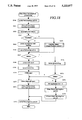
- FIGS. 8 to 13 are flow charts illustrating the operation of a display CPU of the body
- FIGS. 14 to 15 are flow charts illustrating the operation of a main CPU of the body.
- FIGS. 16 through 22 are flow charts illustrating the operation of a lens CPU.
- a camera body 1 includes a main CPU 10 for processing various kinds of photographic information, and a display CPU 11 which mainly performs information input by means of a switch, transmitting and receiving information with respect to a taking lens and displaying the same.
- the display CPU 11 is connected to an LCD panel 12 for displaying a variety of information, and to a Dx code input circuit 13 for inputting an ISO sensitivity of a film, which is to be used from a Dx code printed on a patrone.
- the main CPU 10 is connected to a light-receiving element 14 via an A/D circuit 15.
- the light-receiving element 14 determines a luminance flux of an object coming through a photographing lens 2.
- the main CPU 10 is further connected to an exposure control circuit 16 which controls a shutter based on various input photographing conditions, a CCD processing circuit 18 for detecting a focal condition of the photographing lens 2 from an output of an automatic focus (AF) CCD 17, an AF motor control circuit 20 for driving an AF motor 19 for automatic focussing of the lens 2, and an AF pulser 21 for detecting a pulse number of a drive of the AF motor 19.
- AF automatic focus
- the AF motor 19 is adapted to transmit a drive force to the interchangeable lens barrel 2 by means of a coupler 19a that is mounted on a mount aperture.
- a battery 22 supplies electrical power to an active element within the above-mentioned camera body and also supplies electric power to any applicable motors and/or CPU's within the interchangeable lens barrel 2.
- the lens barrel 2 includes a lens CPU 30 for transmitting and receiving information relative to the body side or for processing information in the lens 2.
- the focus mechanism 31 which performs a focusing by moving a focusing lens group in an optical axis direction, and a zoom mechanism 32 for performing zooming by moving variable power lens groups in the optical axis direction.
- the focus mechanism 31 includes a coupler 31a which connects to the coupler 19a when the lens 2 is mounted on the body 1.
- the focus mechanism 31 performs the focusing operation by means of power supplied thereto through the couplers 19a and 31a.
- the focus mechanism also permits manual operation thereof for the focusing operation when it is disengaged from the coupler 19a.
- the zoom mechanism 32 is capable of being driven by a power zoom (PZ) motor 34 which is controllably driven by the lens CPU 30 through a power zoom motor drive circuit 33.
- the zoom mechanism 32 is designed so as to be selectively driven by either a manual operation or by the motor 34 depending on which is selected through a change-over operation, which will be explained later.
- Means for inputting information relative to the lens CPU 30 include use of a PZ pulser 35 for detecting a drive amount of the PZ motor 34 in terms of pulse numbers; a zoom-operation code plate 38 for inputting information regarding the direction and speed of the power zoom, which works by operating the distance code plate 36 for inputting position information of the lens which has been determined by the focus mechanism 31, a zoom code plate for inputting a focal length of the lens 2 which has been determined by the zoom mechanism 32, and a zoom operation ring 51.
- the code plates 36 and 37 are usually constructed by combining a code plate fixed to a rotatable cam ring and a plurality of brushes secured to a fixed ring which slidably engages with the code plate. Although an absolute rotational position of each of the cam rings is detected by the engagement state of the code plate and the brush, the code plates 36 and 37 are generally indicated as a code plate for clarification.
- FIGS. 2A and 2B show its main part.
- FIG. 2A shows an accommodated position of the lens 2
- FIG. 2B shows a shooting position of the lens 2.
- the lens barrel 2 is provided with a stationary lens barrel 53 on its outside, and the zoom operation ring 51 is mounted on a periphery of the stationary lens barrel 53 so that the ring 51 can rotate about the optical axis.
- a decoration barrel 57 is mounted so that it can move freely in the optical axis direction.
- an inner barrel portion 58 is formed, and a zoom cam ring 59 is supported on an inside of the inner barrel portion 58 to rotate freely.
- a focus cam ring 61 is supported on an outside of the zoom cam ring 59 and the inner barrel portion 58 to rotate freely.
- First lens group L1 for focusing is mounted on the inner barrel portion 58.
- Second and third lens groups L2 and L3 for zooming are located inside the zoom cam ring 59.
- the above-mentioned decoration barrel 57 i.e. first lens group L1
- the above-mentioned second and third lens groups L2 and L3 are moved in the optical axis direction in a predetermined spatial relationship by the rotation of the zoom cam ring 59.
- the above-mentioned focusing cam ring 61 is driven by the AF motor 19 via a joint 31a and a gear line 31b, whereas the zoom cam ring 59 is driven by a PZ motor 34 via a gear train 34a.
- the rotating position of the zoom cam ring 61 is detected via the zoom code plate 37, while the position of the focusing cam ring 61 is detected via the focal length code plate 36.
- the decoration barrel 57 retracts to its maximum, and goes into a deepest position of the stationary lens barrel 53, as shown in FIG. 2A, when it is accommodated, resulting in the shortest overall length of the lens 2.
- the decoration barrel 57 extrudes from the stationary lens barrel 53, as shown in FIG. 2B, making the overall length of the lens 2 larger.
- focusing is done in the following manner: the zoom cam ring 59 rotates as the PZ motor 34 rotates, and second and third lens groups L2 and L3 move relative to each other for zooming in the optical axis direction, changing the distance between them.
- the focusing cam ring 61 rotates as the AF motor 19 rotates, and the first lens group L1 (decoration barrel 57) moves in the optical axis direction.
- FIG. 3A illustrates a circuit of a body 1.
- Terminal V DD1 of the display CPU 11 is supplied with voltage from the battery 22 which is transformed by a regulator 23.
- a capacitor 24 backs up the V DD1 terminal so that the terminal is supplied with a constant voltage.
- Terminal P 1 of the display CPU 11 is connected to a DC/DC converter 25 for performing an ON/OFF actuation of power of the main CPU 10.
- Terminal P 2 is connected to a photometric switch SWS which is designed to turn ON upon a first stage depression of a shutter button (not shown).
- Terminal P 3 is connected to a release switch SWR which is designed to turn ON upon a second stage depression of the shutter button.
- Terminal P 4 is connected to a lock switch SWL which is designed to turn ON when the camera is put into a photographing condition. ON/OFF data of each of the switches corresponding to each terminal is inputted to the CPU 11.
- the DC/DC converter 25 is actuated by an instruction from the display CPU 11 when the photometric switch SWS or the release switch SWR is turned ON while the lock switch SWL is in an ON condition, or when data regarding the lens side is inputted so as to supply power to terminal V DD of the main CPU 10 for the actuation thereof.
- Terminal P 5 of the display CPU 11 is connected to a mode switch SWM which permits, in the ON state, selection of the following photographing modes: programmed photography, automatic photography; or manual photography.
- Terminal P 6 is connected to a drive switch SWDR which permits, in the ON state, selection of single photography, sequential photography, etc.
- Terminal P 7 is connected to an exposure correction switch SWXV which, in the ON state, permits correction of a predetermined exposure.
- a group of terminals P SEG is provided so as to drive the LCD panel 12 and is adapted to display various data needed for photography when the lock switch SWL is turned ON.
- Terminals P 10 -P 18 of the display CPU 11 are connected terminal P 10 is connected to body side contact Fmin1; terminal P 11 is connected to body side contact Fmin2; terminal P 12 is connected to body side contact Fmin3; terminal P 13 is connected to body side contact Fmax1; terminal P 14 is connected to body side contact Fmax2; terminal P 15 is connected to body side contact A/M; terminal P 16 is connected to body side contact Cont; terminal P 17 is connected to body contact Vdd; and terminal P 18 is connected to switch circuit contact 26.
- the switch circuit 26 is designed to make switching between body side V BATT contact and the battery 22 by means of a H(High)/L(Low) of the P18 terminal, and body side Gnd contact, which together with the Gnd terminal of the display CPU 11, is connected to a ground side of the battery 22.
- the display CPU 11 and main CPU 10 perform data transfer using instruction commands as shown in Table 1 below through a serial clock terminal SCK, a serial-in terminal SI and a serial-out terminal SO.
- the left column in Table 1 shows code output from the display CPU 11 to the main CPU 10, the codes being set in accordance with data regarding a switch of the body 1, lens ROM, lens CPU, etc.
- the right column in Table 1 indicates data output from the main CPU 10 to the display CPU 11, the data being set in accordance with measurement data obtained by a photo-optical device, distance measurement device, etc., which are controlled by the main CPU 10.
- a group of contacts P A of the main CPU 10 are connected to an A/D circuit 15 for photometry; a group of contacts PB are connected to an exposure control circuit 16; a group of contacts PC are connected to a CCD processing circuit 18; a group of contacts PD are connected to an AF motor control circuit 20; a group of contacts PE are connected to an AF pulser 21 and, a group of contacts PF are connected to a Dx input circuit 13.
- the CCD processing circuit 18 is connected to the AF CCD 17, and the AF motor control circuit 20 is connected to the AF motor 19 in the body.
- Terminal P 20 of the main CPU 10 is connected to a first AF switch SWAF1, which operates to change a focussing mode between an AUTO MODE by means of the AF motor drive and a MANUAL MODE by means of a manual operation of the lens by a user.
- Terminal P 21 is connected to a second AF switch SWAF 2 which operates to change a shutter release mode between a focus-priority mode and a release-priority mode.
- the first and second AF switches SWAF1, SWAF2 are arranged so as to be sequentially operated so that, when the first AF switch SWAF1 selects the MANUAL MODE, the second AF switch SWAF2 changes to the release-priority mode.
- FIG. 3B illustrates a circuit in the lens barrel 2.
- the PZ motor drive unit 33 is connected to a group of terminals PH of the lens CPU 30 so as to be controlled thereby.
- a pulser 35 generates a pulse when the motor 34 rotates and inputs the pulse generated to the lens CPU 30 through the terminal P20.
- the terminals P21 to P29 of the lens CPU are respectively connected to a third AF switch SWAF3, for changing the automatic focus on the lens between AUTO and MANUAL, a zoom change-over switch SWPZ1 which determines whether zooming is to be performed automatically by the motor or manually; an image magnification rate switch SWPZ2 for setting a constant image magnification control for achieving an automatic zooming in accordance with a displacement of the camera relative to an object so as to maintain an image magnification of the object at a constant value; and six switches of the zoom operation code plate 38 that issue a rotational direction and speed of the PZ motor 34. The six switches will be explained later.
- Terminal groups PI and PJ of the lens CPU 30 are connected to the zoom code plate 36 and the distance code plate 37, respectively, so as to input object distance information and focal distance information in accordance with the actual lens condition.
- These contacts are connected to respective contacts on the body as being identically named when the lens 2 is mounted on the body 1.
- the body side is provided with a terminal Vdd so as to accommodate a conventional lens, but the lens side is not provided with a corresponding contact.
- Contact VBatt at the lens side is connected to the PZ motor drive unit 33 so that electricity is directly supplied from the battery 22 inside the camera body to the PZ motor 34 by means of a switching operation of the drive unit 33.
- Contact A/M at the lens side is connected to contact Gnd at the lens side through a diaphragm switch SWA/M for changing the AUTO/MANUAL mode of the diaphragm sequentially in connection with the rotational movement of the diaphragm ring at the lens side.
- Contact Fmax1 and Fmax2 at the lens side are selectively connected to ground through fuse set portions H1 and H2 as a fixed information portion similar to that provided on a conventional AE lens, which will be explained later.
- information of the maximum F number (smallest aperture of the diaphragm) in Table 2 is provided to the body side depending upon the combination of intermittence of the fuse.
- Terminals Fmin1, Fmin2, and Fmin3 at the lens side provide full-open F number (smallest F number, largest aperture of the diaphragm) in 3 bits and are used as an input/output terminal for the lens CPU 30.
- these contacts are connected to PNP transistors Tr1-Tr3.
- An emitter of each transistor is connected to respective Fmin1, Fmin2, and Fmin3 contacts, with the base thereof being connectable to the CONT contact through fuse-set portions H3, H4, and H5, while a collector thereof is being connected to the Gnd contact.
- the fuse can be positioned between the emitter and Fmin contact.
- the electrical potential of the CONT contact is made to be the same as that of the Gnd contact so that the fuse will make the transistor which is in a connected state ON, and the three contacts Fmin1, Fmin2, and Fmin3 are made to be "H" (High level).
- the contact Fmin1 in a connected state is L(low level), while the contacts Fmin2 and Fmin3 are "H”. That is, this achieves a construction in which each contact appears to be provided with respective memory cells of a ROM, so that each contact is able to store information in one bit by means of intermittence of a fuse connected to a base of each of the transistor.
- Contact CONT on the lens side is connected to the above transistor and is arranged so as to supply electric power to a Vdd terminal of the lens CPU 30 through a switching circuit 39 and to a reset circuit that comprises a resistor R, a diode D and a capacitor C.
- the switching of electric power supply from the CONT terminal is performed by the Fmin1 terminal on the lens side, so that electric power can be supplied to the lens CPU 30 by setting the CONT contact "H" while Fmin1 contact is at "L” after having provided information about the full-open F number.
- the reset circuit is provided with a predetermined time constant by means of the resistor R and the capacitor C, and it is hence capable of starting a program of the lens CPU by changing a RESET terminal of the lens CPU 30 from ACTIVE ("L”) TO NONACTIVE ("H") when a predetermined amount of time has passed after activation of the Vdd and voltage of the power becomes constant.
- Contact Fmin2 on the lens side is connected to the SCK terminal of the lens CPU 30, which outputs clock signals to the display CPU 11 on the body side for serial communication.
- Contact Fmin3 is connected to a DATA terminal of the lens CPU 30 to achieve serial data transmission.
- the system of communication between the lens and the body is shown in a timing chart in FIG. 4.
- the body side actuates the lens CPU 30 to reset itself by making the CONT terminal "H” while making the Fmin1 terminal “L,” when information of the full-open F number has been read by the CONT terminal "L.”
- the body side changes the DATA terminal from "L” to"H” after confirming that the DATA (Fmin3) terminal at the lens CPU side is "H” (NOT BUSY), so as start communication relative to the lens CPU 30.
- the CONT and RESET terminals hold their given condition once the lens CPU 30 was started.
- the lens CPU 30 outputs a clock signal from the SCK terminal so as to input a command from the body side by means of the DATA line. If the data constitutes a necessary command, the lens CPU 30 outputs an acknowledgment signal, and thereafter, data transfer will be achieved.
- the lens CPU 30 changes the DATA terminal to "H” once after making it “L” and thereafter transmits completion of communication to the body side.
- the zoom operation code plate 38 will now be explained hereinbelow.
- the lens 2 is constructed so that the zoom operation can be performed either by the MANUAL MODE or MOTOR DRIVEN MODE. It is, however, arranged so that the zoom operation, by means of the motor driven mode can be performed with a feeling similar to that obtained during the manual mode operation.
- the operation ring 51 is provided around the center periphery of the lens barrel so that the direction (TELE, WIDE) and speed of zooming can be determined by means of the rotational operation of the operation ring 51.
- the operation ring 51 is rotatable from the neutral position in opposite rotational directions and is also biased by means of a pair of springs 53 so that it returns to the neutral position when the user releases it.
- the operation ring 51 is provided with four brushes.
- a stationary barrel (not shown) rotatable relative to the operation ring 51 has the code plate 38 fixed thereto, which is adapted to change its state of conduction due to a slidable movement of the brushes.
- the code plate 38 is formed, as shown in FIG. 5, with a land on the ground and three conduction lands each on the TELE (FAR) side and WIDE (NEAR) side.
- FAR TELE
- NEAR WIDE
- the brushes sliding on the code plate 37 function to communicate any communication lands with which the brushes come into contact with in their displacement position with the land on the ground so that, upon communication, a signal "1" is inputted to terminals to P24 ⁇ P29 of the lens CPU 30, while, upon non-communication, a signal "0" is input to terminals P24 ⁇ P29.
- 7 kinds of signals are output from each FAR and NEAR side on the opposite sides of the neutral position in correspondence with a given rotational position. These signals are transformed into single bit data for use in a process in which the direction and speed of zooming are selected.
- Zoom speeds determined by the initial operational position and rotational angle are shown below the code plate 37 in FIG. 5. Though the way to determine the zoom speed will be explained later with reference to a flow chart, a brief explanation thereof will be given below.
- the zoom speed becomes low if the rotational angle is equal to or less than F2. At a greater rotational angle, the zoom speed becomes moderate in the case of F3 and F4, while the zoom speed becomes high in the case of F5.
- the zoom speed can be determined solely by a rotational angle as a parameter, as mentioned above.
- the power zoom device is constructed so as to stop the zooming mechanism when the operation ring is moved towards a smaller code number, i.e., closer to the neutral position (NT), regardless of the amount of rotational angle from the neutral position, so that it is capable of stopping the lens at a desired focal length at any zoom speed.
- a camera of this embodiment is constructed so that the zooming speed can be determined not only by the amount of rotation of the operation ring 51 from the neutral position, but also by the initial operational position, i.e., the position from where zooming starts.
- the initial operational position i.e., the position from where zooming starts.
- FIG. 6 illustrates an example in which PWM (Pulse Width Modulation) is used as a means for varying the above zooming speed.
- PWM Pulse Width Modulation
- the camera according to this embodiment is intended to solve the above problems by improving the control system of a motor, while maintaining the above curvature characteristic between the rotational angle of the zoom ring and focal length changes. That is to say, a constant change in focal length can be obtained, even in a case in which a constant speed zooming command is given to the camera, by constructing a control circuit for zooming so that the motor is automatically controlled to be driven rapidly at the WIDE side, while, on the TELE side is driven slowly.
- a constant rate focal length change at a given speed can be obtained by multiplying ⁇ by the power supply time of the PWM determined by the above speed data.
- Correction data of each of the increments may be stored in ROM 30a of the lens CPU 30 so as to obtain any correction data corresponding to the focal length data detected by the zoom code plate 37.
- FIG. 8 shows a timer routine for the display CPU 11. This process is executed by the display CPU 11 according to the program stored in an internal ROM of the display CPU 11.
- the display CPU 11 checks the ON/OFF condition of the lock switch SWL in Steps S1 and S2 (shown as only S in the figure). If lock switch SWL is OFF, switch interruption is disabled in step S3, and it is determined whether the lens enclosure has been completed, based upon the condition of flag FLOCK.
- the camera is designed so that the lens is automatically retracted with the most compact condition by automatic focusing and power zooming at the time the lock switch SWL is turned OFF.
- this camera memorizes the conditions before the accommodation, and directs itself to return to the conditions before accommodation when the lock switch SWL is ON.
- Such a design can be used without inconvenience even when the lock switch SWL is OFF for accommodation or for other purposes.
- accommodation for the AF and the resumption of its position prior to accommodation are executed by the main CPU 10, while the accommodation for PZ and its resumption are executed directly by the lens CPU 30.
- the main CPU 10 and the lens CPU 30 are activated only when necessary.
- the display CPU 11 which operates all the time, controls the data for accommodation and resumption of initial position.
- the lock switch SWL functions as the means for changing the states between the accommodated and ready-for-photographing positions.
- Steps S5 through S8 are processes for the lens accommodation.
- the process for zooming is executed by sending an accommodation (retraction) command to the lens CPU 30 and by obtaining focal length data before accommodation from the lens CPU 30.
- the AF process AF is executed by activating the main CPU 10 by the AF enclosure subroutine, as shown in FIG. 9. The AF accommodation will be described later.
- Step S8 When the lens accommodation is completed, flag FLOCK is set to "0" (Step S8). If the lens accommodation has already been completed, the process is skipped because flag FLOCK is "0.” Power supply for the lens CPU 10 is turned OFF by changing P16 (CONT) to "L” in Step S9, and power for the LCD panel 12 is turned OFF in Step S10. Then, the timer is set to execute the timer routine intermittently at an interval of 125 ms in Steps S11, S12 and S13, and the process stops. This intermittent process is repeated while the lock switch SWL is OFF.
- the display CPU 11 checks the condition of flag FLOCK in Step S14, and if it is "0," it returns the lens focus condition to the condition before accommodation by having the main CPU 10 execute the AF resumption process of FIG. 10.
- Step S16 the kind of lens being mounted to the body is checked by calling a data input process, as shown in FIG. 12, and if necessary, the resumption of the position of the zoom lens for use is executed.
- Step S17 When the above-mentioned subroutine is completed and the execution is returned to the timer routine, the display CPU 11 enables switch interruptions in Step S17 and advances the process to Step S18.
- Steps S18 through S25 the process involves changing the mode and altering its display according to the operation of the as mode switch SWMode, drive switch SWDR, exposure compensation switch SWXv, up switch SWUp, and down switch SWDn.
- Both the accommodation and resumption processes are to wait for flags FAFREC (enclosure) and FAFRET (resume) until they are cleared by executing a serial interruption. These flags have been set at the first step by changing P1 to "H” to turn ON the DC/DC converter 25 to start the main CPU 10.
- the serial interruption process is executed when there is an interruption from the main CPU 10.
- a command code is entered in Step S30, and if it is judged to be other than the AF accommodation or the resumption process in Step S31, the process of the command code is executed in Step S32.
- Step S33 and S34 it is determined whether it is the AF accommodation or the resumption process, based upon the flag condition in Steps S33 and S34.
- an AF accommodation code is sent to the main CPU 10 in Step S35.
- Steps S36 through S38 the amount of rotation necessary for accommodation of the AF motor 19 is entered as the number of pulses from the AF pulser 21. Then the flag FAFREC is cleared and execution returns to the process that called it.
- an AF resume code is sent to the main CPU in Step S39, and in Steps S40 through S43, the number of pulses that was entered before the accommodation is sent as the number of pulses for the resumption process. It waits until the resumption process is completed, clears flag FAFRET, and then the process starts over again after having received a resume completion code from the main CPU 10.
- the subroutine for data input that is called in Step S16 of the timer routine clears all three flags FAE, FNo. and FCPU, which are used to determine the lens in Step S50.
- Step S51 each port P10 through P12 used to communicate with the lens is changed to an input mode, and the level of the Cont contact point P16 is entered and measured.
- the Cont contact point of the body makes a contact with the mount ring causing a ground voltage (L). Because of this, the minimum (full opening) and maximum F numbers, and the aperture A/M selection are read in as a 6-bit parallel data in Step S54.
- Step S55 flag FAE showing the use of an AE lens is set, and then the execution returns to the timer routine.
- Step S56 When the level of the Cont terminal P16 is "H,” it is reset at the "L” level in Step S56, and the levels of terminals P10 to P15 are inputted in Step S57.
- Step S57 When a lens shown in FIG. 3B is mounted, the transistor connected to contact point Fmin1, Fmin2, and Fmin3 is turned ON in this step, and the open F number is inputted.
- Steps S58 and S59 P16 (CONT) is set “H,” and P10 (Fmin1) is set “L.” This makes power supplied to the lens CPU 30 from the CONT terminal of the body, and after a certain period of time, the reset is released and the lens CPU 30 starts operating.
- Steps S60 through S63 if both ports P13 and P14 are "H,” it is determined that a lens is not mounted, flag FNO is turned ON and the execution returns. As shown in Table 2, it is so designed that either terminal P13 or terminal P 14 (Fmax) becomes "0.”
- Step S61 When a lens is mounted, the judgment in Step S61 becomes negative.
- the contact point levels of terminal P10 to terminal P 12 are detected after setting the Cont contact point to "H.” If the level of any contact point detected is "L,” the lens CPU 30 is judged a failure.
- Flag FNO is turned ON in Step S63 and the execution returns. This is because all of the terminals P10 to P12 maintain the "H" condition at the communication-wait state of the lens CPU 30.
- flag FLOCK is set to "0" right after the lock switch is changed from ON to OFF, and is set to "1" right after the lock switch is changed from OFF to ON.
- Step S70 a command code 60H is sent to the lens CPU 30, which is synchronized with a clock from the lens CPU 30.
- This code is to receive lens information including switch positions of the lens and power hold request, etc., as shown in Table 4. Such lens information is inputted in Step S71.
- Step S72 When a power hold request from the lens CPU 30, based on the input data is detected in Step S72, terminal P18 (VBATT) is set to "H,” and the power supply to the PZ motor drive 34 in the lens is started in Steps S73 and S74. Then, a command code 92H, informing a power hold, is sent out to the lens CPU 30.
- a command code 93H informing a power hold cancellation, is sent to the lens CPU 10 in Step S75, and the PZ motor is turned OFF by lowering the VBATT to "L" in Step S77 after a certain period of time has elapsed.
- Steps S78 through S81 data is entered from the lens by command codes 61 and 33.
- Step S82 flag FCPU is set to "1", showing that a lens with a lens CPU is mounted, and then the execution returns to the timer routine.
- FIG. 13 shows a subroutine for an interruption process by SWS, and SWR of the display CPU 11.
- Step S90 another switch interruption is disabled in Step S90, the main CPU 10 is turned ON in Step S91, and the aforementioned serial interruption is enabled in Step S92.
- Steps S93 through S97 are repeated to input the information that frequently changes from the lens ROM and lens CPU 30. And, setting alteration processes for the same mode, drive and exposure compensation, such as those shown in Steps S18 through S25 in the timer routine, are executed.
- Steps S98 through S101 If either one of the lock switch SWL or light-measuring switch SWS is OFF, the power supply to the main CPU 10 is turned OFF, the timer is set, timer interruption is enabled, and execution is terminated in Steps S98 through S101.
- the DC/DC converter is turned ON when terminal P1 is changed to "H" by the display CPU 11. Then, power is supplied to the main CPU 10 and the process starts.
- Step S110 the RAM port is initialized, and an AF accommodation-resumption code is sent to the display CPU 11 in Step 111. After this, a command code from the display CPU 11 is read in Step S112.
- Steps S113 and S114 determine whether the command code is for an AF accommodation or an AF position resumption.
- the AF motor 19 is driven until the lens reaches the accommodated position, and the number of pulses from this drive is sent out to the display CPU 11 as the resume information in Steps S115 through S118.
- Step S119 a request for power hold OFF is made, and the process is terminated. If the command code is for resumption, the AF motor 19 is driven according to the number of pulses obtained from the display CPU 11 in Steps S120 through S123-2 to resume the lens focusing condition to the condition before accommodation.
- Step S124 If the command code is neither accommodation nor resumption, it is determined whether the light-measuring switch SWS or the release switch SWR is ON in Step S124.
- Step S119 the display CPU 11 is requested to turn OFF the power hold in Step S119, and the process is terminated.
- Step S125 When either the light-measuring switch SWS or the release switch SWR is on, a request for power hold ON is sent out to the display CPU 11 in Step S125. Then, in Steps S126 through S129, the light-measuring A/D and DX information are entered from the A/D circuit 15 and DX input circuit 13, respectively. Then, the lens data and the selected shutter speed Tv and aperture Av are entered from the display CPU 11, and Tv and Av are computed.
- Step S130 the main CPU 10 transfers computed data Tv and Av to the display CPU 11 to display it on the LCD panel 12.
- Step S131 the ON/OFF state of the release switch SWR is checked in Step S131.
- Step S146 When the release switch SWR is ON, if the AF is in the manual mode, flag FAF is set to "0+ and execution proceeds to Step S146 (FIG. 15), and a release process is executed. If the AF is in the automatic mode, flag FAF is set to "1," and it is determined whether it is a focus-priority mode or release-priority mode in Step S138. In the event that it is release-priority mode, execution proceeds to Step S146. Whether it is AF automatic or manual operation is determined based on the lens switch SWAF3 and the body switch SWAF2. In this case, the setting of the switch at the lense has priority.
- Steps S139 and S140 a defocus amount is obtained by entering the AF data from the CCD processing circuit 18 and execution proceeds to Step S141 in FIG. 15.
- Step S142 When judged to be in focus in Step S141 of FIG. 15, it is determined in Step S142 whether it is the focus-priority mode or release-priority mode.
- a focus lock is activated after the release switch SWR is turned ON while the light-measuring switch SWS is ON in Steps S142 and S143.
- the release process is followed in Step S146 by turning ON the release switch SWR.
- execution proceeds to Step S145, and a shutter release takes place immediately if the release switch SWR is ON. If the release switch SWR is OFF, the lens moving process takes place with the release unlocked in Step S150 onward.
- Step S146 a shutter release takes place at a selected shutter speed and aperture.
- the main CPU 10 drives the winding motor (not shown) to wind the film in Step S147.
- Drive C i.e. a sequential mode
- the execution immediately goes back to Step S124 in FIG. 14.
- Step S124 In the case of a single mode, it goes back to Step S124 after the release switch SWR is turned OFF.
- Step S141 when the focus is judged to be out-of-focus in Step S141, or when it is judged to be in-focus with the light-measuring switch SWS OFF at the focus-priority mode, or the release switch SWR is OFF at the release-priority mode, the automatic or manual mode is determined by flag FAF in Step S150.
- the automatic mode the AF motor 19 is driven according to the number of pulses which is calculated based on the amount of defocus in Steps S151 through S154.
- the manual focusing mode the execution goes back to Step S124 in FIG. 14A after skipping Steps S151 through S154.
- FIGS. 16 through 21 The operation of the lens CPU 30 is explained below using FIGS. 16 through 21. These operations and processes are executed according to a program stored in ROM 30a of the lens CPU 30.
- FIG. 16 shows a main flow chart of the lens CPU 10.
- the lens CPU 10 is activated by releasing the reset by the release circuit after the CONT contact point and the Fmin1 contact point are set to "H" by a command from the display CPU 11.
- the lens CPU 11 disables all the interruptions described below in Step S200, executes an initialization in Step S201, and forms a loop in Steps S202 through S215.
- Step S202 data from each switch installed on the lens, the distance code plate 36 and the zoom code plate 37 are read in. These data are stored in RAM 30b in Step S203, and the process is executed in later steps based on these data.
- Steps S204 through S208 a zooming mode, that is, by power zoom or manual zoom is determined by the setting of the PZ switch of the lens.
- flag FPZ is set to "1" if either switch is ON, and the power hold request bit is set to "1"; execution then proceeds to Step S209.
- Step S208-2 In the manual zoom mode, or when all the switches are OFF in the power zoom mode, the power hold request bit is set to "0" in Step S208-2, and execution proceeds to Step S209.
- Steps S209 through S211 flag FCONST is set to "1" when a constant-magnification control is selected, or the flag is set to "0" when the control is not selected.
- Step S212 serial interruptions are enabled in Step S212, as described below.
- a 125 ms timer is set in Steps S213 through S215 and started. Then, timer interruptions are enabled and execution is halted until an interruption occurs.
- FIG. 17 shows the flow chart for the serial interruption process of the lens CPU 30 for input/output of data and commands, which is executed when there is a serial interruption from the display CPU 11 of the body 1.
- Step S222 a command code from the body is read in by using the output of the clock for communication.
- "H" and "L" of each contact point are shown in FIG. 4 mentioned above.
- Step S223 and the following steps are a routine that executes processes according to specific commands.
- Step S223 whether a 2/4 code is correct is checked in Step S223.
- the upper four bits of a command code consists of two 1's and two 0's. Because of this, if these conditions are not met, it is an input error of the command code, and no processes are executed. In such a case, interruptions are enabled in Steps S249 and S250, and then execution returns to the main routine.
- Step S234 If the 2/4 code is judged to be correct, it is determined whether the command code is a data request in Step S234. If it is a data request, the data required in Step S235 is set in RAM 30b, and sent to the display CPU 11 in Step S236. Then, execution proceeds to Step S249.
- Step S237 If the command code is not a data request, it is determined whether the code is 90H in Step S237. If it is 90H, which means a PZ accommodation, the present data of the focal length is sent to the display CPU 11 as data for the resumption position in Step S238. After the PZ motor 34 is driven so that the lens is moved to the accommodated position in Step 2239, execution proceeds to Step S249.
- Step S240 If the command code is not 90H, it is determined whether the code is 91H in Step S240. If it is 91H, which means PZ position resumption, the data of the focal length which was obtained for accommodation is entered as input from the display CPU 11 in Step S241. The PZ motor 34 is driven in Step S242 so as to adjust the lens to the focal length before its accommodation. Then, the process proceeds to Step S249.
- 91H which means PZ position resumption
- Step S243 it is determined whether the code is 92H in Step S243. If it is 92H, which means that the power hold of the PZ motor VBATT is turned ON in the body, the PH request bit is set to "1" in Step S244. In Steps S245 and S246, a 10 ms timer is started, as mentioned later, after enabling an interruption for 10 ms. Then execution proceeds to Step S249.
- Step S247 If the command code is not 92H, it is determined whether it is 93H in Step S247. If it is 93H, which means the power hold is OFF, the PH request bit is set to "0" in Step S248, and execution proceeds to Step S249.
- FIG. 18 illustrates a timer interruption process of the lens CPU 30. This process is executed to control the power zooming at a 10 ms interval when it is made possible during a serial interruption, as mentioned above.
- Step S262 a subroutine for detecting zooming extremities is called, as shown in FIG. 19.
- This extremity points detecting process functions to detect when the zoom lens has reached its tele-extremity or wide-extremity.
- Step S280 the condition of flag FPULSE is checked in Step S280. If there is no change in the PZ pulse and the flag is "0,” counter CPUL is incremented in Step S281. When the P2 pulse changes and flag FPULSE is set to "1", counter CPUL becomes "1". Thus, Step S285 is performed to clear CPUL and Step S284 is executed. Then, it is determined whether the counter CPUL is greater than or equal to 10, or not, is checked at step S282. Flag FPULSE is set to "1" when the PZ pulse changes.
- flag FBRK is set to "1" to apply a brake to the PZ motor 34 in Step S283, and flag FPULSE is cleared in Step S284. Then, the execution returns.
- Step S283 is skipped, and Step S284 is executed.
- flag FBRK is set to "1" when there are no changes in the PZ pulse within 100 ms, and it is determined that the lens has reached the extremities.
- Step S263 When the execution returns from the extremities detecting process to the 10 ms timer interruption process, the state of the flag FCONST is checked in Step S263.
- Flag FCONST is set based on the ON/OFF condition of SWPZ2 in the main routine mentioned above. If this flag is "1," the constant image magnification control is executed in Step S264.
- the constant image magnification control is the control that makes the subject size on the film constant by changing the lens magnification when the distance between the subject and camera is changed. It is done in the following manner. The change in the magnification is calculated from the defocus amount of the subject which once was in focus but has moved. Then, the change in magnification is converted to the driving pulse of the PZ motor 34 to control the motor. A detailed explanation about this process is not given here.
- Step S265 If flag FCONST is "0,” a zoom operation code 38 is read in Step S265, and a zooming direction and speed are determined by executing a subroutine for selecting a speed and a direction in Step S266.
- Step S267 it is determined whether the brake should be applied to the PZ motor 34 from the condition of flag FBRK. If not brake is applied, a zoom code corresponding to the focal length is read in from the zoom code plate 3 in Step S268. In accordance with this, the PWM control value is compensated by the speed compensation process in Step S269. Flag FBRK becomes "1" in both cases where the lens has reached the terminal point, or a zoom halt has been indicated by operating the zoom operation ring 51.
- the camera operates so as to hold the focal length change constant by adjusting the rotating speed of the PZ motor 34.
- a speed correction process is the process that enables such control.
- correction data is set in Step S300, as shown in FIG. 20.
- the compensation data is represented by a formula, where f'(xn) is a rate of change in the nth division and f'(xmax) is a maximum rate of change in all the divisions:
- Step S301 the PWM current supplying time that holds the focal-length changing rate constant can be obtained by multiplying the above Beta by the PWM current supplying time which is determined by the speed data described below.
- Step S302 limits the computed value within a certain range to prevent the motor from stopping when the calculated current supplying time is too small.
- Step S270 Upon completion of the speed compensation process, the PZ motor 34 starts driving in Step S270.
- the 10 ms timer is set and started in Step S271. Then, all interruptions are enabled in Steps S272 and S273, and execution returns.
- a brake is applied to the PZ motor 34 in Step S310. If it is not in the constant magnification mode and if flag FPZ is "0", the brake time is set in Steps S312 through S316 in the same manner as the zooming extremities are detected. Flag FPZ is set to "1" when the zoom is driven in the speed & direction selection process described later.
- Step S314 counter CBRK is incremented by 1 to measure the break time, and it is determined whether the counter becomes greater than or equal to 10 in Step S315. If it is greater than or equal to 10, flag FBRK is set to "0" in Step S316, and the execution returns. When it is smaller than 10, Step S316 is skipped and the execution returns.
- Step S276 When the brake process is completed and flag FBRK becomes "0,” the power hold request bit is set to "0" in Step S276 and the 10 ms timer interruption is disabled in Step S277. 125 ms timer interruptions and serial interruptions are enabled, and execution returns in Steps S278 and S273.
- FIG. 22 shows a subroutine which selects a speed and direction.
- This subroutine is called from Step S266 (FIG. 18), which is for the 10 ms timer interruption process of the lens CPU 30.
- This process determines the direction and the speed of the zooming according to the operating conditions of the zoom operating ring, and is a concrete method to enable the judgments shown at the bottom of FIG. 5.
- 6-bit data entered from ports P24 through P29 of the lens CPU 30 is converted to a 1-byte code according to Table 5, shown below.
- variables to store the conversion codes in RAM 30b are as follows:
- the conversion code is stored in DN in Step S320.
- flag FPZ is cleared in Steps S322 through S324. Then, when flag FBRK is set to "1" and the code in DN is stored into DO, execution returns.
- Step S325 If the position is not neutral, flag FPZ is set to "1" in Step S325, and the driving direction is determined in Steps S326 through S331.
- DNH and DOH are equal, that is, the zoom operation ring 51 has not been changed, it is determined whether it is moved toward one of the zooming extremities or towards the neutral position. If the operation is toward the neutral position, flag FBRK is turned ON in Step S323 and execution returns.
- the starting position for movement (the initial position) is set to the neutral position, and a speed selection is done in Steps S332 and onward.
- flag FBRK was set to "1" in the previous process determines if it is being driven or not. If flag FBRK was set to "1" in the previous process, and if there is no change in the code, execution starts again after going through Steps S323 and S324. If there is a change in the code, the process goes into a speed-setting routine after establishing the previous code as the code for initial position. If the flag FBRK was not "1" in the previous process, the process goes into a speed-setting routine immediately.
- Steps S332 through S345 the process goes into a speed-setting routine based on the starting position of the zoom operation ring 51 (the initial position) and the number of revolutions, as shown at the bottom of FIG. 5.
- speed data DSPED is set to high in Step S348 when the rotating position of the zoom operation ring 51 is greater than 4, set to medium in Step S347 when it is between 2 and 4, and set to low in Step S346 when it is smaller than 2.
- the starting position is F1, or N1, high is selected when the rotating position of the zoom operation ring 51 is greater than 5, medium when it is between 3 and 5, and low when it is smaller than 2.
- the starting position is F2 or N2
- high is selected when the rotating position of the zoom operation ring 51 is greater than 6, medium when it is between 4 and 6, and low when it is smaller than 3.
- the starting position is F3, F4, N3 or N4, high is selected when the rotating position of the zoom operation ring 51 is greater than 6, medium when it is between 5 and 6, and low when it is smaller than 4.
- the starting position is F5, or N5, high is selected when the rotating position of the zoom operation ring 51 is greater than 6, and low when it is smaller than 5.
- the starting position is F6, F7, N6 or N7, only low is selected, even when the rotating position changes.
- a driving direction DDIRC is set at data DDIRC in Step S349, flag FBRK is cleared in Step S350, the code in DN is stored into DO in Step S351, and execution starts over again.
- revolution speed of the PZ motor 34 is adjusted by the process for the constant focal-length changing rate, enabling zooming at a constant changing rate.
- the zooming speeds can be selected at four levels, or changed continuously.
- this invention can be applied to lens shutter type cameras, movie cameras or the like.
- this invention of the power zoom system enables easy zooming even when a zoom switch with many positions are used to control it, because the driving direction and the speed of zooming the camera lens are controlled based on the setting positions before and after its operation.
- this invention of the power zoom system enables the focal length change of the lens to be held constant by compensation even when the focal length changing rate to a constant amount of rotation is not constant because of a cam ring design.
Applications Claiming Priority (2)
| Application Number | Priority Date | Filing Date | Title |
|---|---|---|---|
| JP2-34608 | 1990-02-15 | ||
| JP2034608A JPH03237440A (ja) | 1990-02-15 | 1990-02-15 | カメラシステム、カメラボディ、撮影レンズ |
Publications (1)
| Publication Number | Publication Date |
|---|---|
| US5223877A true US5223877A (en) | 1993-06-29 |
Family
ID=12419078
Family Applications (1)
| Application Number | Title | Priority Date | Filing Date |
|---|---|---|---|
| US07/656,223 Expired - Lifetime US5223877A (en) | 1990-02-15 | 1991-02-15 | Camera system |
Country Status (5)
| Country | Link |
|---|---|
| US (1) | US5223877A (ja) |
| JP (1) | JPH03237440A (ja) |
| DE (1) | DE4104722A1 (ja) |
| FR (1) | FR2658326B1 (ja) |
| GB (1) | GB2241075A (ja) |
Cited By (14)
| Publication number | Priority date | Publication date | Assignee | Title |
|---|---|---|---|---|
| US5349409A (en) * | 1990-07-06 | 1994-09-20 | Asahi Kogaku Kogyo Kabushiki Kaisha | Photographing lens |
| US5355192A (en) * | 1990-09-14 | 1994-10-11 | Asahi Kogaku Kogyo Kabushiki Kaisha | Automatic focusing apparatus |
| US5416555A (en) * | 1990-04-26 | 1995-05-16 | Asahi Kogaku Kogyo Kabushiki Kaisha | Camera system and photographing lens thereof |
| US5576894A (en) * | 1993-10-21 | 1996-11-19 | Minolta Co., Ltd. | Zoom lens barrel based on the vari-focal optical system |
| US5617173A (en) * | 1991-05-21 | 1997-04-01 | Asahi Kogaku Kogyo Kabushiki Kaisha | Camera system having power zoom lens |
| EP0806704A1 (en) * | 1996-05-10 | 1997-11-12 | Canon Kabushiki Kaisha | System for communication between camera and accessory |
| US6167208A (en) * | 1997-11-05 | 2000-12-26 | Asahi Kogaku Kogyo Kabushiki Kaisha | Camera having data processor enabling external processing of image data |
| US20020118963A1 (en) * | 2001-02-28 | 2002-08-29 | Asahi Kogaku Kogyo Kabushiki Kaisha | Camera system having a communication system between a camera body and a photographing lens |
| US6654554B2 (en) | 2001-02-19 | 2003-11-25 | Pentax Corporation | Power controller of a camera having an interchangeable lens |
| US6741808B2 (en) | 2001-02-19 | 2004-05-25 | Pentax Corporation | Camera system having a communication system between a camera body and a photographing lens |
| US6766111B2 (en) | 2001-02-28 | 2004-07-20 | Pentax Corporation | Camera system having a communication system between a camera body and a photographing lens |
| US20040165078A1 (en) * | 2003-02-05 | 2004-08-26 | Tadashi Sasaki | Lens apparatus |
| US20090051789A1 (en) * | 2007-08-22 | 2009-02-26 | Canon Kabushiki Kaisha | Imaging apparatus |
| US10835342B2 (en) * | 2017-03-02 | 2020-11-17 | Sony Olympus Medical Solutions Inc. | Medical observation apparatus and control method |
Citations (18)
| Publication number | Priority date | Publication date | Assignee | Title |
|---|---|---|---|---|
| GB1532576A (en) * | 1976-03-19 | 1978-11-15 | Schneider Co Optische Werke | Control device for variable focal-length lenses |
| US4404595A (en) * | 1980-01-15 | 1983-09-13 | Canon Kabushiki Kaisha | Lens unit for a camera |
| DE3329897A1 (de) * | 1982-09-06 | 1984-03-08 | Olympus Optical Co., Ltd., Tokyo | Kamera mit automatischer steuerung der scharfeinstellung |
| US4541700A (en) * | 1982-07-22 | 1985-09-17 | Ernst Leitz Wetzlar Gmbh | Method and devices for transferring electrical signal information between a photographic lens and camera |
| US4560267A (en) * | 1982-03-26 | 1985-12-24 | Minolta Camera Kabushiki Kaisha | Camera system operable by carrying data from a camera accessory to a camera body |
| US4596449A (en) * | 1982-12-14 | 1986-06-24 | West Electric Company Ltd. | Zoom lens apparatus |
| US4673275A (en) * | 1982-03-26 | 1987-06-16 | Minolta Camera Kabushiki Kaisha | Camera system operable by carrying data from a camera accessory to a camera body |
| US4682871A (en) * | 1985-09-02 | 1987-07-28 | Minolta Camera Kabushiki Kaisha | Aperture value information switchable lens barrel |
| US4737812A (en) * | 1985-08-05 | 1988-04-12 | Nippon Kogaku K.K. | Automatic focusing camera |
| US4739356A (en) * | 1986-07-23 | 1988-04-19 | Canon Kabushiki Kaisha | Electric connector for camera |
| JPS63184719A (ja) * | 1986-10-01 | 1988-07-30 | Asahi Optical Co Ltd | 撮影レンズ |
| US4777164A (en) * | 1983-04-28 | 1988-10-11 | The Dow Chemical Company | Method and composition for enhancing the insecticidal activity of certain organophosphorus compounds |
| US4788567A (en) * | 1985-12-27 | 1988-11-29 | Hideo Hamano | Output information system for an interchangeable lens |
| US4816859A (en) * | 1988-03-28 | 1989-03-28 | Chinon Kabushiki Kaisha | Zoom lens focusing apparatus |
| US4896181A (en) * | 1986-03-31 | 1990-01-23 | Nikon Corporation | Camera system |
| US4936664A (en) * | 1986-05-12 | 1990-06-26 | Asahi Kogaku Kogyo Kabushiki Kaisha | Zoom lens drive system for camera |
| US5060005A (en) * | 1988-11-17 | 1991-10-22 | Olympus Optical Co., Ltd. | Camera system |
| US5065175A (en) * | 1988-09-13 | 1991-11-12 | Asahi Kogaku Kogyo Kabushiki Kaisha | Single-lens reflex camera system |
-
1990
- 1990-02-15 JP JP2034608A patent/JPH03237440A/ja active Pending
-
1991
- 1991-02-15 US US07/656,223 patent/US5223877A/en not_active Expired - Lifetime
- 1991-02-15 GB GB9103224A patent/GB2241075A/en not_active Withdrawn
- 1991-02-15 FR FR9101807A patent/FR2658326B1/fr not_active Expired - Fee Related
- 1991-02-15 DE DE4104722A patent/DE4104722A1/de not_active Withdrawn
Patent Citations (18)
| Publication number | Priority date | Publication date | Assignee | Title |
|---|---|---|---|---|
| GB1532576A (en) * | 1976-03-19 | 1978-11-15 | Schneider Co Optische Werke | Control device for variable focal-length lenses |
| US4404595A (en) * | 1980-01-15 | 1983-09-13 | Canon Kabushiki Kaisha | Lens unit for a camera |
| US4560267A (en) * | 1982-03-26 | 1985-12-24 | Minolta Camera Kabushiki Kaisha | Camera system operable by carrying data from a camera accessory to a camera body |
| US4673275A (en) * | 1982-03-26 | 1987-06-16 | Minolta Camera Kabushiki Kaisha | Camera system operable by carrying data from a camera accessory to a camera body |
| US4541700A (en) * | 1982-07-22 | 1985-09-17 | Ernst Leitz Wetzlar Gmbh | Method and devices for transferring electrical signal information between a photographic lens and camera |
| DE3329897A1 (de) * | 1982-09-06 | 1984-03-08 | Olympus Optical Co., Ltd., Tokyo | Kamera mit automatischer steuerung der scharfeinstellung |
| US4596449A (en) * | 1982-12-14 | 1986-06-24 | West Electric Company Ltd. | Zoom lens apparatus |
| US4777164A (en) * | 1983-04-28 | 1988-10-11 | The Dow Chemical Company | Method and composition for enhancing the insecticidal activity of certain organophosphorus compounds |
| US4737812A (en) * | 1985-08-05 | 1988-04-12 | Nippon Kogaku K.K. | Automatic focusing camera |
| US4682871A (en) * | 1985-09-02 | 1987-07-28 | Minolta Camera Kabushiki Kaisha | Aperture value information switchable lens barrel |
| US4788567A (en) * | 1985-12-27 | 1988-11-29 | Hideo Hamano | Output information system for an interchangeable lens |
| US4896181A (en) * | 1986-03-31 | 1990-01-23 | Nikon Corporation | Camera system |
| US4936664A (en) * | 1986-05-12 | 1990-06-26 | Asahi Kogaku Kogyo Kabushiki Kaisha | Zoom lens drive system for camera |
| US4739356A (en) * | 1986-07-23 | 1988-04-19 | Canon Kabushiki Kaisha | Electric connector for camera |
| JPS63184719A (ja) * | 1986-10-01 | 1988-07-30 | Asahi Optical Co Ltd | 撮影レンズ |
| US4816859A (en) * | 1988-03-28 | 1989-03-28 | Chinon Kabushiki Kaisha | Zoom lens focusing apparatus |
| US5065175A (en) * | 1988-09-13 | 1991-11-12 | Asahi Kogaku Kogyo Kabushiki Kaisha | Single-lens reflex camera system |
| US5060005A (en) * | 1988-11-17 | 1991-10-22 | Olympus Optical Co., Ltd. | Camera system |
Non-Patent Citations (1)
| Title |
|---|
| English translation of German Office Action. * |
Cited By (21)
| Publication number | Priority date | Publication date | Assignee | Title |
|---|---|---|---|---|
| US5416555A (en) * | 1990-04-26 | 1995-05-16 | Asahi Kogaku Kogyo Kabushiki Kaisha | Camera system and photographing lens thereof |
| US5505535A (en) * | 1990-04-26 | 1996-04-09 | Asahi Kogaku Kogyo Kabushiki Kaisha | Camera system and photographing lens thereof |
| US5713052A (en) * | 1990-04-26 | 1998-01-27 | Asahi Kogaku Kogyo Kabushiki Kaisha | Camera system and photographing lens thereof |
| US5349409A (en) * | 1990-07-06 | 1994-09-20 | Asahi Kogaku Kogyo Kabushiki Kaisha | Photographing lens |
| US5355192A (en) * | 1990-09-14 | 1994-10-11 | Asahi Kogaku Kogyo Kabushiki Kaisha | Automatic focusing apparatus |
| US5617173A (en) * | 1991-05-21 | 1997-04-01 | Asahi Kogaku Kogyo Kabushiki Kaisha | Camera system having power zoom lens |
| US5664234A (en) * | 1991-05-21 | 1997-09-02 | Asahi Kogaku Kogyo Kabushiki Kaisha | Camera system having power zoom lens |
| US5576894A (en) * | 1993-10-21 | 1996-11-19 | Minolta Co., Ltd. | Zoom lens barrel based on the vari-focal optical system |
| EP0806704A1 (en) * | 1996-05-10 | 1997-11-12 | Canon Kabushiki Kaisha | System for communication between camera and accessory |
| US5781818A (en) * | 1996-05-10 | 1998-07-14 | Canon Kabushiki Kaisha | System for communication between camera and accessory |
| US6167208A (en) * | 1997-11-05 | 2000-12-26 | Asahi Kogaku Kogyo Kabushiki Kaisha | Camera having data processor enabling external processing of image data |
| US6654554B2 (en) | 2001-02-19 | 2003-11-25 | Pentax Corporation | Power controller of a camera having an interchangeable lens |
| US6741808B2 (en) | 2001-02-19 | 2004-05-25 | Pentax Corporation | Camera system having a communication system between a camera body and a photographing lens |
| US20020118963A1 (en) * | 2001-02-28 | 2002-08-29 | Asahi Kogaku Kogyo Kabushiki Kaisha | Camera system having a communication system between a camera body and a photographing lens |
| US6707992B2 (en) | 2001-02-28 | 2004-03-16 | Pentax Corporation | Camera system having a communication system between a camera body and a photographing lens |
| US6766111B2 (en) | 2001-02-28 | 2004-07-20 | Pentax Corporation | Camera system having a communication system between a camera body and a photographing lens |
| US20040165078A1 (en) * | 2003-02-05 | 2004-08-26 | Tadashi Sasaki | Lens apparatus |
| US7035021B2 (en) * | 2003-02-05 | 2006-04-25 | Fuji Photo Optical Co., Ltd. | Lens apparatus |
| US20090051789A1 (en) * | 2007-08-22 | 2009-02-26 | Canon Kabushiki Kaisha | Imaging apparatus |
| US8154626B2 (en) * | 2007-08-22 | 2012-04-10 | Canon Kabushiki Kaisha | Imaging apparatus having enhanced zoom operation |
| US10835342B2 (en) * | 2017-03-02 | 2020-11-17 | Sony Olympus Medical Solutions Inc. | Medical observation apparatus and control method |
Also Published As
| Publication number | Publication date |
|---|---|
| DE4104722A1 (de) | 1991-08-22 |
| FR2658326A1 (fr) | 1991-08-16 |
| GB9103224D0 (en) | 1991-04-03 |
| JPH03237440A (ja) | 1991-10-23 |
| GB2241075A (en) | 1991-08-21 |
| FR2658326B1 (fr) | 1993-10-01 |
Similar Documents
| Publication | Publication Date | Title |
|---|---|---|
| US5159370A (en) | Powered zoom device | |
| US5223877A (en) | Camera system | |
| EP0718672B1 (en) | Converting adapter for interchangeable lens assembly | |
| US5065175A (en) | Single-lens reflex camera system | |
| US5066969A (en) | Camera system | |
| US5347333A (en) | Lens-driving device for camera | |
| JPH06265991A (ja) | カメラシステム | |
| US5166717A (en) | Camera system | |
| US5066968A (en) | Autofocusing system for a camera | |
| US5255046A (en) | Camera system | |
| US5182591A (en) | Camera system | |
| US5198847A (en) | Power zooming device | |
| US5181061A (en) | Camera system | |
| US5170200A (en) | Camera system | |
| US5255043A (en) | Apparatus for maintaining constant image magnification in a camera system | |
| JP4660859B2 (ja) | レンズ装置 | |
| US5170203A (en) | Camera system | |
| GB2241069A (en) | Camera having powered zoom lens with depth of field priority zoom mode | |
| US6128443A (en) | Camera and interchangeable lens | |
| US5305044A (en) | Autofocusing system for a camera | |
| JPH0470614A (ja) | 撮影レンズ | |
| JPH0612371B2 (ja) | 前玉固定ズ−ムレンズにおける合焦レンズ移動装置 | |
| US6507703B1 (en) | Camera for producing a trimmed image | |
| JP3334921B2 (ja) | 光学機器 | |
| JP6816787B2 (ja) | 交換レンズ |
Legal Events
| Date | Code | Title | Description |
|---|---|---|---|
| AS | Assignment |
Owner name: ASAHI KOGAKU KOGYO KABUSHIKI KAISHA, 36-9, MAENOCH Free format text: ASSIGNMENT OF ASSIGNORS INTEREST.;ASSIGNORS:TAKAHASHI, HIROYUKU;IWAMOTO, SHIGERU;KAWASAKI, MASAHIRO;REEL/FRAME:005642/0465 Effective date: 19910318 |
|
| STCF | Information on status: patent grant |
Free format text: PATENTED CASE |
|
| CC | Certificate of correction | ||
| FEPP | Fee payment procedure |
Free format text: PAYOR NUMBER ASSIGNED (ORIGINAL EVENT CODE: ASPN); ENTITY STATUS OF PATENT OWNER: LARGE ENTITY |
|
| FPAY | Fee payment |
Year of fee payment: 4 |
|
| FEPP | Fee payment procedure |
Free format text: PAYOR NUMBER ASSIGNED (ORIGINAL EVENT CODE: ASPN); ENTITY STATUS OF PATENT OWNER: LARGE ENTITY Free format text: PAYER NUMBER DE-ASSIGNED (ORIGINAL EVENT CODE: RMPN); ENTITY STATUS OF PATENT OWNER: LARGE ENTITY |
|
| FPAY | Fee payment |
Year of fee payment: 8 |
|
| FPAY | Fee payment |
Year of fee payment: 12 |