US5115714A - Apparatus for infeeding cartridges - Google Patents
Apparatus for infeeding cartridges Download PDFInfo
- Publication number
- US5115714A US5115714A US07/671,111 US67111191A US5115714A US 5115714 A US5115714 A US 5115714A US 67111191 A US67111191 A US 67111191A US 5115714 A US5115714 A US 5115714A
- Authority
- US
- United States
- Prior art keywords
- cartridge
- firing
- endless chain
- cartridges
- weapon
- Prior art date
- Legal status (The legal status is an assumption and is not a legal conclusion. Google has not performed a legal analysis and makes no representation as to the accuracy of the status listed.)
- Expired - Fee Related
Links
Images


Classifications
-
- F—MECHANICAL ENGINEERING; LIGHTING; HEATING; WEAPONS; BLASTING
- F41—WEAPONS
- F41A—FUNCTIONAL FEATURES OR DETAILS COMMON TO BOTH SMALLARMS AND ORDNANCE, e.g. CANNONS; MOUNTINGS FOR SMALLARMS OR ORDNANCE
- F41A9/00—Feeding or loading of ammunition; Magazines; Guiding means for the extracting of cartridges
- F41A9/37—Feeding two or more kinds of ammunition to the same gun; Feeding from two sides
-
- F—MECHANICAL ENGINEERING; LIGHTING; HEATING; WEAPONS; BLASTING
- F41—WEAPONS
- F41A—FUNCTIONAL FEATURES OR DETAILS COMMON TO BOTH SMALLARMS AND ORDNANCE, e.g. CANNONS; MOUNTINGS FOR SMALLARMS OR ORDNANCE
- F41A9/00—Feeding or loading of ammunition; Magazines; Guiding means for the extracting of cartridges
- F41A9/01—Feeding of unbelted ammunition
- F41A9/04—Feeding of unbelted ammunition using endless-chain belts carrying a plurality of ammunition
Definitions
- the present invention relates to a new and improved apparatus for controllably infeeding cartridges from a stationary magazine or supply container to a firing weapon, especially to a multi-barrel gun or cannon.
- the cartridge infeed apparatus for a firing weapon is of the type comprising gate or switch means for switching-on and switching-off the infeed of the cartridges, a first endless chain for the delivery of the cartridges from the gate or switch means to the firing weapon, and a second endless chain with controllable return for the delivery of the cartridges from the stationary magazine to the gate or switch means.
- the cartridge infeed apparatus of the present development is particularly suitable for use in conjunction with firing weapons having an external drive, for instance, Gatling-type guns or the like.
- a Gatling-type gun or cannon possesses a cluster or array of weapon barrels.
- the run-up of the firing weapon until reaching its full or maximum firing rate or cadence leads to pronounced round scattering, and thus, the first round to be fired should only then be fired after the cluster or array of weapon barrels has attained its set or reference rotational speed, in other words, during the time that the firing weapon runs up to speed ammunition rounds should not be fired.
- the cartridge infeed apparatus itself requires a certain amount of time until it has attained the full or maximum cartridge infeed velocity.
- this cartridge infeed apparatus should possess the capability of infeeding two different types of ammunition.
- European Patent Application No. 0, 020,095, published Dec. 10, 1980 teaches a prior art construction of cartridge infeed apparatus of the aforementioned general type, wherein there is provided a storage or accumulator.
- a transport chain is guided through an infeed channel, a supply or storage channel and through a return channel.
- the infeed channel opens into a transfer station of the firing weapon.
- a gate or switch At the transfer location between the infeed channel and the storage or supply channel there is arranged a gate or switch. In one position of the gate, ammunition moves from the infeed channel to a further infeed system having a second transport chain leading to the transfer station of the firing weapon. In the other position of this gate, ammunition at the transport chain moves through the supply or storage channel into the return channel.
- Another and more specific object of the present invention aims at the provision of an improved apparatus for the infeed of cartridges to a firing weapon which first feeds cartridges to the firing weapon after the firing weapon has run up to speed and there has been simultaneously reached the full cartridge infeed velocity, and after each series firing or firing burst there can be rapidly and reliably established the initial conditions.
- Still a further noteworthy object of the present invention is the provision of a new and improved ammunition infeed apparatus which takes into account both the run up to speed of the firing weapon and also the time needed for the running up to speed of the ammunition infeed apparatus.
- the cartridge infeed apparatus of the present development is manifested, among other things, by the features that two transfer wheels are arranged between the first endless chain and the second endless chain.
- a clutch operatively interconnects the two transfer wheels with one another.
- a sensor serves to determine the starting position of the first or lead cartridge, which is to be delivered to the firing weapon, at the second endless chain.
- a separate channel serves for the return of the spent cartridge casings from the first endless chain, and the gate means is switched and thereafter the clutch is de-activated for the termination of a firing burst or series firing.
- One of the more notable advantages of the present invention resides in the fact that there is not only taken into account the run up to speed of the firing weapon but also the time needed for the cartridge infeed apparatus to run up to speed and such conditions can be exactly accommodated to one another.
- two different types of ammunition can be infed, in order to selectively use cartridges from the one stationary ammunition magazine or a second stationary ammunition magazine.
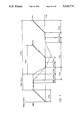
- FIG. 1 schematically illustrates in side view a gun mounting structure, here shown, for instance, as an armored turret equipped with two multi-barrel firing weapons, so-called Gatling-type guns or cannons;
- FIG. 2 schematically illustrates in front view the armored turret of FIG. 1;
- FIG. 3 schematically illustrates in top plan view the armored turret of FIG. 1;
- FIG. 4 schematically illustrates in front view the cartridge infeed apparatus of the arrangement of FIGS. 1 to 3;
- FIG. 5 schematically illustrates in perspective view the armored turret of FIGS. 1 to 3;
- FIGS. 6, 6a and 6b schematically illustrate, in respective enlarged views, details of the cartridge infeed apparatus
- FIG. 7 is a diagram portraying the operation of the firing weapon during individual firing bursts, wherein the firing weapon operation is depicted in the curve shown in full or solid lines and the ammunition or cartridge feed operation is depicted in the curve shown in chain-dot lines;
- FIG. 8 is a schematic detail view of the entire firing weapon system.
- FIG. 1 of the drawings there is depicted an armored turret 10 or equivalent structure which is appropriately rotatably mounted upon the deck of a vessel or upon a vehicle platform 11.
- FIGS. 1 and 2 there are pivotably mounted two multi-barrel firing weapons 12 and 13, so-called Gatling-type guns or cannons, at the armored turret 10 for rotation about an elevation axis 14.
- the two multi-barrel firing weapons 12 and 13 can be elevated out of their horizontal disposition, shown in full lines, into different positions; for example, they can be elevationally lowered through an angle of about 30° into the position 12a, or elevated through an angle of about 42.5° into the position 12b, or elevated through an angle of about 115° into the position 12c.
- each of the two multi-barrel firing weapons 12 and 13 contains an array of seven weapon barrels 15
- Each multi-barrel firing weapon 12 and 13 has located therebelow three ammunition or cartridge magazines 16, 17, 18 and 19, 20, 21, respectively, as particularly well shown in FIG. 3.
- the ammunition or cartridge magazines 16 and 19 which are located most forwardly, as viewed in the weapon firing direction, contain a first type of ammunition and the ammunition or cartridge magazines 18 and 21 which are located rearmost, again as viewed in the weapon firing direction, contain a second type of ammunition.
- Both of the intermediately disposed ammunition or cartridge magazines 17 and 20 serve for reception of the empty or spent cartridge casings.
- a respective supply channel 16a, 17a, 18a, 19a, 20a and 21a extends from each ammunition magazine or container 16, 17, 18, 19, 20 and 21, respectively, to one of the two multi-barrel firing weapons 12 and 13, respectively.
- FIG. 5 clearly depicts these six channels 16a, 17a, 18a, 19a, 20a and 21a.
- Within the channels 16a and 19a one type of ammunition or cartridges are delivered to the respective multi-barrel firing weapons 12 and 13, and in the channels 18a and 21a there are delivered the other type of ammunition or cartridges to the multi-barrel firing weapons 12 and 13, respectively.
- the empty or spent cartridge casings of both ammunition types move through the return channels 17a and 21a for deposit into the intermediate ammunition magazines 17 and 20, respectively.
- Each of three respective channels 16a, 17a, 18a and 19a, 20a, 21a lead into a respective common housing 22 and 23.
- a first elastic or flexible channel 24 extends from the first housing 22 to the first multi-barrel firing weapon 12 and a second elastic or flexible channel 25 extends from the second housing 23 to the second multi-barrel firing weapon 13.
- endless chains 16b and 19b or equivalent feed structure are located in the channels 16a and 19a, respectively, by means of which the cartridges 32 from the respective ammunition magazines 16 and 19 can be transported to the housings 22 and 23, respectively.
- endless chains 24a and 25a or the like are likewise arranged in the elastic or flexible channels 24 and 25, respectively, and by means of these endless chains 24a and 25a the cartridges 32 can be delivered from the housings 22 and 23, respectively, to the multi-barrel firing weapons 12 and 13, respectively.
- Endless chains 16c and 19c or equivalent structure are likewise located in the respective ammunition magazines 16 and 19, in which endless chains 16c and 19c the cartridges 32 are first of all stored, and secondly, transported to the endless chains 16b and 19b.
- Comparable endless chains which have not been shown to simplify the illustration, are equally located in the ammunition magazines 18 and 21. In FIG. 4 there are shown the further endless chains 18b and 21b which are located in the respective channels 18a and 21a.
- FIG. 6 depicts the transfer of the cartridges 32 from the endless chains 16b or 18b to the common endless chain 24a.
- Two transfer wheels or sprockets 26a and 26b or equivalent structure are arranged between the endless chain 16b and the endless chain 24a.
- two further transfer wheels or sprockets 27a and 27b or equivalent structure are arranged between the endless chain 18b and the endless chain 24a.
- a first gate or switch 28 renders possible the transfer of the cartridges 32 from the endless chain 16b to the first transfer wheel 26a when this gate or switch 28 is in a first operating position. In the other operating position of this gate or switch 28 the cartridges 32 remain upon the endless chain 16b and are returned back to the ammunition magazine 16.
- a second gate or switch 29 allows transfer of the cartridges 32 from the endless chain 18b to the third transfer wheel 27a whenever this second gate or switch 29 is located in its first operating position. In the other operating position of the gate or switch 29 the cartridges 32 remain upon the endless chain 18b and are moved back to the ammunition magazine 18.
- These gates 28 and 29 each contain two deflection segments or elements 30 and 31, and at any given time the one or the other deflection segment 30 or 31 is effective or operable. Assuming that the deflection segment 30 of the gate 28 is operable, then the cartridges 32 arrive from the endless chain 16b at the transfer wheel 26a. In the event that the other deflection segment 31 of the gate 28 is operable, then the cartridges 32 remain upon the endless chain 16b. The same is analogously true for the two deflection segments 30 and 31 of the second gate 29.
- a third gate or switch 42 is arranged between the two transfer wheels 26b and 27b and the first endless chain 24a.
- the deflection segment 31 is operative and the cartridges 32 arrive from the deflection wheel 26b at the endless chain 24a.
- the other deflection segment 30 is now operative and the cartridges 32 arrive from the deflection wheel 27b at the endless chain 24a.
- Each of the four channels 16a, 18a, 19a and 21a have associated therewith a respective sensor 50 or 51, the position of which is determinative of the starting position of the first or initial or lead cartridge 32 which is to be delivered to the associated firing weapon 12 and 13.
- both the endless chain 16b and also the endless chain 18b are trained about a respective deflection wheel or sprocket 33 and 34 or equivalent chain deflection or turning structure.
- the deflection wheel 33 of the endless chain 16b is in drive connection with the transfer wheel 26a by means of two gears 43 and 44.
- the deflection wheel 34 of the endless chain 18b is in drive connection with the transfer wheel 27a by means of two gears 45 and 46.
- the endless chain 24a is trained about a deflection wheel or sprocket 39.
- This deflection wheel 39 of the endless chain 24a is in drive connection with the transfer wheel 26b by means of two gears 49 and 47.
- this deflection wheel 39 of the endless chain 24a is in drive connection with the transfer wheel 27b by means of the gear 49 and the further gear 48.
- the gears 43 and 44 can be brought into meshing relationship by means of a clutch 35 or the like, and equally, the gears 45 and 46 can be brought into meshing relationship by means of a clutch 36 or the like. If the clutch 35 is engaged, then cartridges 32 can be transferred from the endless chain 16b and the transfer wheels 26a and 26b to the endless chain 24a. On the other hand, if the other clutch 36 is engaged, then cartridges 32 can be transferred from the other endless chain 18b to the endless chain 24a by means of the transfer wheels 27a and 27b.
- cartridges 32 either are delivered from the ammunition magazine 16 to the multi-barrel firing weapon 12, or, when the other clutch 36 is engaged or activated, then cartridges 32 are delivered from the other ammunition magazine 18 to the multi-barrel firing weapon 12.
- these clutches 35 and 36 render possible the selective switching from one type of ammunition to another type of ammunition, and hence, constitute switching means for the selective infed of cartridges from one or the other ammunition magazine 16 or 18 or 19 or 21 to the respective multi-barrel firing weapons 12 and 13.
- the gates 28 and 29 allow the determination from which ammunition magazine the first cartridge 32 should be delivered to the multi-barrel firing weapon 12 and that point in time when there should be interrupted the delivery of cartridges 32 to the multi-barrel firing weapon 12. For the reasons previously stated, comparable observations are valid as concerns the cartridge infeed apparatus associated with the other multi-barrel firing weapon 13.
- a second gear 52 of exactly the same size as the gear 44, is located behind this gear 44.
- the gear 44 is continuously in mesh with the next gear 47 and the other gear 52 is continuously in mesh with the neighboring gear 43.
- Both of the gears 44 and 52 which are arranged in tandem upon the same shaft, can be brought into mesh with one another by the aforementioned clutch 35.
- This clutch 35 is composed of two clutch halves or portions 53 and 54 which can be brought into engagement with one another by axially displacing the same hydraulically for instance, and a suitable resilient element, such as a spring 55 exerts the requisite force for disengaging the interengaged clutch halves or portions 53 and 54.
- a suitable resilient element such as a spring 55 exerts the requisite force for disengaging the interengaged clutch halves or portions 53 and 54.
- the other clutch 36 shown in FIG. 8 such is of the exact same construction as the just described clutch 35 and therefore need not be here further considered.
- first endless chain 24a or 25a upon activating the related multi-barrel firing weapon 12 or 13, does not receive any cartridges 32, a certain amount of time is needed until the first or lead cartridge 32 has reached the corresponding multi-barrel firing weapon 12 or 13.
- the length of this first endless chain 24a or 25a is chosen such that at the time there is reached the required weapon firing rate the first or lead cartridge 32 has reached the associated multi-barrel firing weapon 12 or 13.
- the corresponding clutch 35 or 36 must be disengaged at the proper point in time before termination of the firing burst, so that the cartridges 32 remaining upon the first endless chain 24a or 25a, as the case may be, can be fired, without there being delivered cartridges 32 from the second or third endless chains 16b, 19b or 18b, 21b such that after completion of the firing burst the corresponding first endless chain 24a or 25a is again empty.
- the multi-barrel firing weapons 12 and 13 and the first endless chains 24a and 25a, respectively, are driven by a suitable associated drive motor 37.
- a gun gate or switch 38 enables interrupting the infeed of cartridges 32 to the corresponding multi-barrel firing weapon 12 or 13.
- this gun gate 38 is switched-in or activated, then the cartridges 32 are delivered by the associated endless chain 24a or 25a to the related multi-barrel firing weapon 12 or 13, respectively.
- the gun gate 38 is switched-off or de-activated, for instance, in the presence of a so-called hang fire, then the cartridges 32 no longer are fed to the associated multi-barrel firing weapon 12 or 13, rather are transported back by the associated endless chain 24a or 25a.
- first endless chains 24a and 25a are each guided over a respective pair of deflection wheels or sprockets 39 or the like and travel through the elastic or flexible channels 24 and 25, respectively.
- the second endless chains 16b and 19b extend from the first ammunition magazines 16 and 19, respectively, to the first endless chains 24a and 25a, respectively.
- the third endless chains 18b and 21b extend from the second ammunition magazines 18 and 21, respectively, to the first endless chains 24a and 25a, respectively.
- the clutch 35 By means of the clutch 35 the respective first endless chains 24a and 25a and the respective second endless chains 16b and 19b can be coupled with one another.
- the other clutch 36 the respective first endless chains 24a and 25a and the respective third endless chains 18b and 21b can be coupled with one another.
- each gate 28 As long as each gate 28 is activated or switched-in, the cartridges 32 move from the respective second endless chains 16b and 19b to the first endless chains 24a and 25a, respectively. If the respective gate 28 is switched-over or thrown, then the cartridges 32 remain upon the respective second endless chains 16b and 19b and are re-cycled or conveyed back to the first ammunition magazines 16 and 19, respectively.
- the same observations are valid for each of the other gates 29. As long as each such gate 29 is switched-in, cartridges 32 are moved from the respective third endless chains 18b and 21b to the first endless chains 24a and 25a, respectively. If each gate 29 is switched-over or thrown, then the cartridges 32 remain upon the respective third endless chains 18b and 21b and are transported back to the second ammunition magazines 18 and 21, respectively.
- a respective endless chain 16c, 18c, 19c and 21c is located in each of the four ammunition magazines 16, 18, 19 and 21, respectively, these chains 16c, 18c, 19c and 21c being operatively connected with an associated drive motor 40 or 41, as the case may be, for the drive of these four endless chains 16c, 18c, 19c and 21c.
- the not here shown trigger of the multi-barrel firing weapon 12 or 13, as the case may be, is activated.
- the drive motors 37, 40 and 41 of the multi-barrel firing weapons 12 and 13 and the ammunition magazines 16, 19 and 18, 21, respectively are activated, depending upon which type of ammunition is desired to be fired.
- the one or the other of the clutches 35 or 36, and the three gates 28, 29 and 42, depicted in FIG. 6, must be properly positioned.
- the first or lead cartridge 32 which is delivered to the corresponding multi-barrel firing weapon 12 or 13 should be located at the region of the associated sensor 50 or 51, depending upon the desired type of ammunition to be fired (see FIG. 6).
- These cartridges 32 arrive at the transfer wheels 26a and 26b or the transfer wheels 27a and 27b, as the case may be, and from that location are delivered to the endless chains 24a and 25a.
- the first or lead cartridge 32 arrives at the relevant multi-barrel firing weapon 12 or 13. As seen from FIG. 7, after, for example, 0.5 seconds there is fired the first ammunition round.
- the relevant one of the gates 28 or 29 (FIG. 6) is activated, and shortly thereafter, the relevant one of the clutches 34 or 35, that is to say, the gate 28 or 29 is positioned such that no cartridges 32 are infed and the clutch 34 or 35, as the case may be, is de-activated or disengaged when the transfer wheel 26a or 27a no longer carries any cartridges 32.
- the relevant multi-barrel firing weapon 12 or 13 comes to standstill, that is to say, until the weapon barrels 15 stop rotating, all of the cartridges 32 located upon the endless chain 24a or 25a, as the case may be, are fired.
Landscapes
- Engineering & Computer Science (AREA)
- General Engineering & Computer Science (AREA)
- Manufacturing Of Cigar And Cigarette Tobacco (AREA)
- Warehouses Or Storage Devices (AREA)
- Toys (AREA)
Applications Claiming Priority (2)
| Application Number | Priority Date | Filing Date | Title |
|---|---|---|---|
| CH109590 | 1990-04-02 | ||
| CH01095/90 | 1990-04-02 |
Publications (1)
| Publication Number | Publication Date |
|---|---|
| US5115714A true US5115714A (en) | 1992-05-26 |
Family
ID=4202357
Family Applications (1)
| Application Number | Title | Priority Date | Filing Date |
|---|---|---|---|
| US07/671,111 Expired - Fee Related US5115714A (en) | 1990-04-02 | 1991-03-18 | Apparatus for infeeding cartridges |
Country Status (4)
| Country | Link |
|---|---|
| US (1) | US5115714A (de) |
| EP (1) | EP0450297B1 (de) |
| JP (1) | JPH04225799A (de) |
| DE (1) | DE59100924D1 (de) |
Cited By (11)
| Publication number | Priority date | Publication date | Assignee | Title |
|---|---|---|---|---|
| US5271310A (en) * | 1991-08-30 | 1993-12-21 | Oerlikon-Contraves Ag | Apparatus for infeeding cartridges of two different types of ammunition to a gatling-type gun |
| US5614689A (en) * | 1994-09-30 | 1997-03-25 | Cta International | Ammunition feed system and method |
| US5675110A (en) * | 1994-07-22 | 1997-10-07 | Cta International | Dual ammunition feeding system for a fire arm and method for feeding different ammunition types using a common transfer mechanism |
| RU2150655C1 (ru) * | 1999-03-23 | 2000-06-10 | Государственное унитарное предприятие "Конструкторское бюро приборостроения" | Спаренная артиллерийская установка |
| WO2001006197A1 (en) * | 1999-07-16 | 2001-01-25 | Metal Storm Limited | Multi-barrel assembly feed for gun |
| RU2165578C1 (ru) * | 1999-10-12 | 2001-04-20 | ОАО Акционерная компания "Туламашзавод" | Артиллерийская установка |
| RU2184919C2 (ru) * | 2000-05-17 | 2002-07-10 | Государственное унитарное предприятие "Конструкторское бюро приборостроения" | Способ формирования внутренней поверхности рукава питания автоматической пушки и устройство для его реализации |
| US20080034952A1 (en) * | 2006-02-14 | 2008-02-14 | Klaus-Dieter Krause | Ammunition feed system with an automatic clutch |
| US20090114085A1 (en) * | 2007-08-31 | 2009-05-07 | Rheinmetall Landsyteme Gmbh | Modular, adaptable ballistic protective construction in particular for a weapons turret |
| US20090120271A1 (en) * | 2007-08-31 | 2009-05-14 | Rheinmetall Landsysteme Gmbh | Ammunition supply system |
| US7908957B1 (en) * | 2008-07-08 | 2011-03-22 | The United States Of America As Represented By The Secretary Of The Army | Synchronized weapon and ammunition container apparatus |
Families Citing this family (1)
| Publication number | Priority date | Publication date | Assignee | Title |
|---|---|---|---|---|
| KR100351275B1 (ko) | 1999-07-19 | 2002-09-09 | 엘지 오티스 엘리베이터 유한회사 | 머신룸 레스 엘리베이터 |
Citations (16)
| Publication number | Priority date | Publication date | Assignee | Title |
|---|---|---|---|---|
| US3041939A (en) * | 1959-10-06 | 1962-07-03 | Dardick Corp | Multi-barrel gun with a plurality of firing stations and an ammunition drum |
| US3995527A (en) * | 1973-02-07 | 1976-12-07 | Keller & Knappich Augsburg Zweigniederlassung Der Industrie-Werke Karlsruhe Augsburg Aktiengesellschaft | Cartridge belt feeding device for automatic weapons |
| EP0020095A1 (de) * | 1979-05-24 | 1980-12-10 | FORD AEROSPACE & COMMUNICATIONS CORPORATION | Zufuhrsystem mit Zwischenspeicher und mit diesem System ausgerüstetes Maschinengewehr |
| FR2468869A1 (fr) * | 1979-11-05 | 1981-05-08 | Gen Electric | Double mecanisme d'alimentation pour mitrailleuse de type gatling |
| GB2092281A (en) * | 1981-02-02 | 1982-08-11 | Gen Electric | High rate fire revolving battery gun |
| US4434699A (en) * | 1979-11-05 | 1984-03-06 | General Electric Company | Ammunition feeder |
| US4434701A (en) * | 1980-05-23 | 1984-03-06 | Creusot-Loire | Apparatus for conveying cylindrical objects such as ammunition |
| DE3342223A1 (de) * | 1982-11-26 | 1984-05-30 | Heckler & Koch Gmbh, 7238 Oberndorf | Patronenzufuehrvorrichtung |
| US4492144A (en) * | 1982-04-05 | 1985-01-08 | General Electric Company | Transport mechanism for ammunition |
| EP0152549A1 (de) * | 1983-12-22 | 1985-08-28 | Werkzeugmaschinenfabrik Oerlikon-Bührle AG | Vorrichtung zum Zuführen von Patronen zu einer Feuerwaffe |
| US4557528A (en) * | 1982-11-26 | 1985-12-10 | Robert Bosch Gmbh | Hydraulic vehicle brake system with brake force amplification and anti-skid regulation |
| US4612843A (en) * | 1983-06-03 | 1986-09-23 | Etat Francais | Dual ammunition feed for automatic weapons |
| US4656922A (en) * | 1984-11-19 | 1987-04-14 | Werkzeugmaschinenfabrik Oerlikon-Buhrle Ag | Monitoring apparatus for monitoring delayed firing cartridges in an externally driven firing weapon |
| US4674392A (en) * | 1982-11-26 | 1987-06-23 | Heckler & Koch Gmbh | Cartridge feed mechanism |
| CH669450A5 (en) * | 1986-02-18 | 1989-03-15 | Oerlikon Buehrle Ag | Ammunition feed for tank mounted weapon - has ammunition on vertical strips advanced to intermediate convector in magazine for transfer to turret conveyor |
| US4836082A (en) * | 1987-08-06 | 1989-06-06 | David Dardick | Cloud gun |
-
1991
- 1991-02-21 DE DE91102526T patent/DE59100924D1/de not_active Expired - Fee Related
- 1991-02-21 EP EP91102526A patent/EP0450297B1/de not_active Expired - Lifetime
- 1991-03-18 US US07/671,111 patent/US5115714A/en not_active Expired - Fee Related
- 1991-04-01 JP JP3068432A patent/JPH04225799A/ja not_active Withdrawn
Patent Citations (20)
| Publication number | Priority date | Publication date | Assignee | Title |
|---|---|---|---|---|
| US3041939A (en) * | 1959-10-06 | 1962-07-03 | Dardick Corp | Multi-barrel gun with a plurality of firing stations and an ammunition drum |
| US3995527A (en) * | 1973-02-07 | 1976-12-07 | Keller & Knappich Augsburg Zweigniederlassung Der Industrie-Werke Karlsruhe Augsburg Aktiengesellschaft | Cartridge belt feeding device for automatic weapons |
| EP0020095A1 (de) * | 1979-05-24 | 1980-12-10 | FORD AEROSPACE & COMMUNICATIONS CORPORATION | Zufuhrsystem mit Zwischenspeicher und mit diesem System ausgerüstetes Maschinengewehr |
| FR2468869A1 (fr) * | 1979-11-05 | 1981-05-08 | Gen Electric | Double mecanisme d'alimentation pour mitrailleuse de type gatling |
| US4434699A (en) * | 1979-11-05 | 1984-03-06 | General Electric Company | Ammunition feeder |
| US4434701A (en) * | 1980-05-23 | 1984-03-06 | Creusot-Loire | Apparatus for conveying cylindrical objects such as ammunition |
| GB2092281A (en) * | 1981-02-02 | 1982-08-11 | Gen Electric | High rate fire revolving battery gun |
| US4359927A (en) * | 1981-02-02 | 1982-11-23 | General Electric Company | High rate of fire revolving battery gun |
| US4492144A (en) * | 1982-04-05 | 1985-01-08 | General Electric Company | Transport mechanism for ammunition |
| US4681018A (en) * | 1982-11-26 | 1987-07-21 | Heckler & Koch Gmbh | Cartridge feed mechanism |
| US4557528A (en) * | 1982-11-26 | 1985-12-10 | Robert Bosch Gmbh | Hydraulic vehicle brake system with brake force amplification and anti-skid regulation |
| US4674392A (en) * | 1982-11-26 | 1987-06-23 | Heckler & Koch Gmbh | Cartridge feed mechanism |
| DE3342223A1 (de) * | 1982-11-26 | 1984-05-30 | Heckler & Koch Gmbh, 7238 Oberndorf | Patronenzufuehrvorrichtung |
| US4765223A (en) * | 1982-11-26 | 1988-08-23 | Heckler & Koch Gmbh | Cartridge feed mechanism |
| US4612843A (en) * | 1983-06-03 | 1986-09-23 | Etat Francais | Dual ammunition feed for automatic weapons |
| EP0152549A1 (de) * | 1983-12-22 | 1985-08-28 | Werkzeugmaschinenfabrik Oerlikon-Bührle AG | Vorrichtung zum Zuführen von Patronen zu einer Feuerwaffe |
| US4656922A (en) * | 1984-11-19 | 1987-04-14 | Werkzeugmaschinenfabrik Oerlikon-Buhrle Ag | Monitoring apparatus for monitoring delayed firing cartridges in an externally driven firing weapon |
| EP0184008B1 (de) * | 1984-11-19 | 1988-01-13 | Werkzeugmaschinenfabrik Oerlikon-Bührle AG | Ueberwachungseinrichtung von Spätzündern für ein fremdangetriebenes Geschütz |
| CH669450A5 (en) * | 1986-02-18 | 1989-03-15 | Oerlikon Buehrle Ag | Ammunition feed for tank mounted weapon - has ammunition on vertical strips advanced to intermediate convector in magazine for transfer to turret conveyor |
| US4836082A (en) * | 1987-08-06 | 1989-06-06 | David Dardick | Cloud gun |
Cited By (13)
| Publication number | Priority date | Publication date | Assignee | Title |
|---|---|---|---|---|
| US5271310A (en) * | 1991-08-30 | 1993-12-21 | Oerlikon-Contraves Ag | Apparatus for infeeding cartridges of two different types of ammunition to a gatling-type gun |
| US5675110A (en) * | 1994-07-22 | 1997-10-07 | Cta International | Dual ammunition feeding system for a fire arm and method for feeding different ammunition types using a common transfer mechanism |
| US5614689A (en) * | 1994-09-30 | 1997-03-25 | Cta International | Ammunition feed system and method |
| RU2150655C1 (ru) * | 1999-03-23 | 2000-06-10 | Государственное унитарное предприятие "Конструкторское бюро приборостроения" | Спаренная артиллерийская установка |
| WO2001006197A1 (en) * | 1999-07-16 | 2001-01-25 | Metal Storm Limited | Multi-barrel assembly feed for gun |
| RU2165578C1 (ru) * | 1999-10-12 | 2001-04-20 | ОАО Акционерная компания "Туламашзавод" | Артиллерийская установка |
| RU2184919C2 (ru) * | 2000-05-17 | 2002-07-10 | Государственное унитарное предприятие "Конструкторское бюро приборостроения" | Способ формирования внутренней поверхности рукава питания автоматической пушки и устройство для его реализации |
| US20080034952A1 (en) * | 2006-02-14 | 2008-02-14 | Klaus-Dieter Krause | Ammunition feed system with an automatic clutch |
| US7669512B2 (en) * | 2006-02-14 | 2010-03-02 | Rheinmetall Air Defence Ag | Ammunition feed system with an automatic clutch |
| US20090114085A1 (en) * | 2007-08-31 | 2009-05-07 | Rheinmetall Landsyteme Gmbh | Modular, adaptable ballistic protective construction in particular for a weapons turret |
| US20090120271A1 (en) * | 2007-08-31 | 2009-05-14 | Rheinmetall Landsysteme Gmbh | Ammunition supply system |
| US8297170B2 (en) | 2007-08-31 | 2012-10-30 | Rheinmetall Landsysteme Gmbh | Modular, adaptable ballistic protective construction in particular for a weapons turret |
| US7908957B1 (en) * | 2008-07-08 | 2011-03-22 | The United States Of America As Represented By The Secretary Of The Army | Synchronized weapon and ammunition container apparatus |
Also Published As
| Publication number | Publication date |
|---|---|
| EP0450297B1 (de) | 1994-01-26 |
| EP0450297A1 (de) | 1991-10-09 |
| JPH04225799A (ja) | 1992-08-14 |
| DE59100924D1 (de) | 1994-03-10 |
Similar Documents
| Publication | Publication Date | Title |
|---|---|---|
| US5115714A (en) | Apparatus for infeeding cartridges | |
| US4326446A (en) | Linkage of actuating system for elevating gun mount | |
| KR20120098726A (ko) | 자동 장약 매거진 | |
| EP0784778A1 (de) | Ansetzer system | |
| US8359964B2 (en) | Weapon system with caseless ammunition | |
| US5408915A (en) | Shell feeder for an automatic gun | |
| US3277787A (en) | Device on an automatic firearm for the selective firing of two kinds of ammunition from two separate belts | |
| US5347911A (en) | Double-action rammer | |
| US4976185A (en) | Ammunition feed | |
| US4127055A (en) | Cartridge feed system for an automatic gun | |
| US6272967B1 (en) | Modular ammunition storage and retrieval system | |
| US5115713A (en) | Apparatus for the infeed of cartridges to a firing weapon | |
| US3995527A (en) | Cartridge belt feeding device for automatic weapons | |
| US3706259A (en) | Multibarrel automatic weapon | |
| EP0020095B1 (de) | Zufuhrsystem mit Zwischenspeicher und mit diesem System ausgerüstetes Maschinengewehr | |
| US3169445A (en) | Magazine mechanism | |
| US4561340A (en) | Two-barrel revolver-type firearm | |
| JPH05215494A (ja) | 主として二つの異なる弾薬種類の弾薬包をガットリング砲に供給するための装置 | |
| US2905056A (en) | Feeder device for the automatic loading of guns | |
| US5245906A (en) | Apparatus for infeeding cartridges of two different types of ammunition to a gatling-type gun | |
| EP0569341B1 (de) | Ansetzer für ein Geschütz | |
| US3776416A (en) | Article handling system | |
| US5070762A (en) | Dual ammunition transfer mechanism | |
| US3733960A (en) | Article handling system | |
| JPH03294793A (ja) | 装薬供給装置 |
Legal Events
| Date | Code | Title | Description |
|---|---|---|---|
| AS | Assignment |
Owner name: OERLIKON-CONTRAVES AG, SCHFFHAUSERSTRASSE 580, CH- Free format text: ASSIGNMENT OF ASSIGNORS INTEREST.;ASSIGNORS:MULLER, KURT;BOHLER, ERWIN;RUPPEN, BRUNO;AND OTHERS;REEL/FRAME:005651/0828;SIGNING DATES FROM 19910305 TO 19910308 |
|
| FEPP | Fee payment procedure |
Free format text: PAYOR NUMBER ASSIGNED (ORIGINAL EVENT CODE: ASPN); ENTITY STATUS OF PATENT OWNER: LARGE ENTITY |
|
| FPAY | Fee payment |
Year of fee payment: 4 |
|
| REMI | Maintenance fee reminder mailed | ||
| LAPS | Lapse for failure to pay maintenance fees | ||
| FP | Lapsed due to failure to pay maintenance fee |
Effective date: 20000526 |
|
| STCH | Information on status: patent discontinuation |
Free format text: PATENT EXPIRED DUE TO NONPAYMENT OF MAINTENANCE FEES UNDER 37 CFR 1.362 |