US4434699A - Ammunition feeder - Google Patents
Ammunition feeder Download PDFInfo
- Publication number
- US4434699A US4434699A US06/311,585 US31158581A US4434699A US 4434699 A US4434699 A US 4434699A US 31158581 A US31158581 A US 31158581A US 4434699 A US4434699 A US 4434699A
- Authority
- US
- United States
- Prior art keywords
- rounds
- sprocket
- gun
- sprocket means
- endless conveyor
- Prior art date
- Legal status (The legal status is an assumption and is not a legal conclusion. Google has not performed a legal analysis and makes no representation as to the accuracy of the status listed.)
- Expired - Lifetime
Links
Images


Classifications
-
- F—MECHANICAL ENGINEERING; LIGHTING; HEATING; WEAPONS; BLASTING
- F41—WEAPONS
- F41A—FUNCTIONAL FEATURES OR DETAILS COMMON TO BOTH SMALLARMS AND ORDNANCE, e.g. CANNONS; MOUNTINGS FOR SMALLARMS OR ORDNANCE
- F41A9/00—Feeding or loading of ammunition; Magazines; Guiding means for the extracting of cartridges
- F41A9/35—Feeding multibarrel guns
- F41A9/36—Feed mechanisms for revolving-cannon guns
-
- F—MECHANICAL ENGINEERING; LIGHTING; HEATING; WEAPONS; BLASTING
- F41—WEAPONS
- F41A—FUNCTIONAL FEATURES OR DETAILS COMMON TO BOTH SMALLARMS AND ORDNANCE, e.g. CANNONS; MOUNTINGS FOR SMALLARMS OR ORDNANCE
- F41A9/00—Feeding or loading of ammunition; Magazines; Guiding means for the extracting of cartridges
- F41A9/37—Feeding two or more kinds of ammunition to the same gun; Feeding from two sides
Definitions
- This invention relates to a feeder for providing either of two independent supplies of ammunition to a Gatling type gun.
- a feature of this invention is the provision a of sprocket which feeds rounds into the gun via an intermediate sprocket and which receives cases from the gun via another intermediate sprocket, and which may be intercoupled with either of two endless conveyors of ammunition.
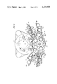
- FIG. 1 is a perspective view of a feeder, in conjunction with a Gatling type gun, embodying this invention
- FIG. 2 is a transverse schematic, looking forward, of the feeder of FIG. 1;
- FIG. 3 is an end schematic, looking forward, of the feeder of FIG. 1;
- FIG. 4 is a detail of FIG. 2 showing the switching of the aft guides for the bases of the rounds;
- FIG. 5 is a detail of FIG. 2 showing the switching of the forward guides for the necks of the rounds;
- FIGS. 6A and 6B are crosssections of FIG. 4 taken at VI-VI;
- FIG. 7 is a crosssection of FIG. 5 taken at VII--VII.
- FIG. 8 is a longitudinal crosssection of the feeder of FIG. 1 showing the drive for the sprocket.
- the Gatling type gun may be of the type shown, for example, by R. E. Chiabrandy et al in U.S. Pat. No. 3,380,343, issued Apr. 30, 1968.
- the gun includes a gun housing 10 in which is journaled a rotor 12 having seven gun barrels 14, each barrel having a respective bore, and seven channels 16, each having a pair of tracks 18 to receive a respective gun bolt 20.
- the gun housing is cut away to clear a right load sprocket 22 having three pockets in each of three blades which are fixed on a right shaft system 24a and 24b and a left unload sprocket 26 having three pockets in each of three blades which are fixed on a left shaft system 28a and 28b.
- the shaft systems 24a and 24b and 28a and 28b, together with a center shaft 30, are journaled in a feeder housing 32 which is fixed to the gun housing 10.
- a center sprocket 34 having five pockets in each of two blades is fixed on the shaft 30.
- a right shaft 40 is hung from and journaled in a front right link 42 and an aft right link 44, which links are pivotally mounted to the fixed feeder housing 32.
- a left shaft 46 is hung from and journaled in a front left link 48 and an aft left link 50, which links are pivotally mounted to the fixed feeder housing 32.
- a shiftable feeder housing 52 is suspended from the shafts 40 and 46 which are journaled therein.
- a control rod 54 is journaled in the fixed feeder housing 32 and has a front cam 56 and an aft cam 58, a switch lever 60 and a push rod 62.
- Each of the cams 56 and 58 is disposed within a respective aperture in the shiftable housing 52.
- the front aperture 64 has a right cam follower surface 66 and a left cam follower surface 68.
- the aft aperture 70 has a right cam follower surface 72 and a left cam follower surface 74.
- a pull on the rod 62 causes counterclockwise rotation of the control rod 54 and a shift to the left of the shiftable housing 52 with respect to the fixed housing 32.
- a push causes clockwise rotation and a shift to the right.
- a right transfer sprocket 76 is fixed to the right shaft 40 and has four pockets in each of two blades which pass through cutouts 78 in the fixed housing 32 and cutouts 80 in the shiftable housing 52.
- a left transfer sprocket 82 is fixed to the left shaft 46 and has four pockets in each of two blades which pass through cutouts in the fixed housing and cutouts 86 in the shiftable housing.
- a right conveyor turnaround sprocket 90 is fixed to a right shaft 92 which is journaled through the shiftable housing 52, and has five pockets in each of two blades.
- a left conveyor turnaround sprocket 94 is fixed to a left shaft 96 which is journaled through the shiftable housing 52, and has five pockets in each of two blades.
- a right endless conveyor 98 including a train of conveyor elements 100 is disposed in the shiftable housing and incorporates the right turnaround sprocket 90, the right load sprocket 22, and the right transfer sprocket 76.
- a similar left endless conveyor 102 including a train of conveyor elements 104, incorporates the left turnaround sprocket 94, the left unload sprocket 26 and the left transfer sprocket 82.
- a timing bar 106 is pivotally mounted on the center shaft 30.
- the bar has a right keyhole cutout 108 receiving the flattened end 110 of the right transfer sprocket shaft 40, and a left keyhole cutout 112 receiving the flattened end 114 of the left transfer sprocket shaft 46.
- a flattened end is in the circular part of the keyhole cutout the shaft is free to rotate, when the flattened end is shifted into the slot of the keyhole cutout the shaft is held against rotation.
- An annular gear 116 is fixed to the gun rotor 12 and is meshed with a right gear 118 which is fixed to the right shaft 24a, which is geared to the load sprocket 22 via a gear 119a fixed to a parallel shaft 119b also having fixed thereto a gear 119c, which in turn is meshed with a gear 119d which is fixed to the shaft 24b.
- a gear 118 is meshed with a left gear 120 which is fixed to the left shaft system 28a and 28b and carries the sprocket 26 similar to the shaft system 24a and 24b.
- a gear 122 and a gear 124 are fixed to the center sprocket shaft 30. The gear 122 is meshed with the right gear 118 and the left gear 120.
- a right gear 126 is fixed to the right transfer sprocket shaft 40 and is meshed with a right gear 128 which is fixed to the right turnaround sprocket shaft 92.
- a left gear 130 is fixed to the left transfer sprocket shaft 46 and is meshed with a left gear 132 which is fixed to the left turnaround sprocket shaft 96.
- a forward right guide assembly 140 and a forward left guide assembly 142 are provided, as shown in FIGS. 5 and 7, to guide the necks of the cartridge cases.
- a right upper guide 144 is mounted by a medial pivot 146 to the shiftable feeder housing 52 and its tail is coupled by a pivot 148 to one end of a link 150 whose other end is coupled by a pivot 152 to the distal end of crank arm 154 whose proximal end is mounted by a pivot 156 to the fixed housing 32 but is medially mounted by a pivot 158 to the shiftable housing 52.
- a right lower guide 160 is mounted by a medial pivot 162 to the shiftable housing 52 and its tail is coupled by a pivot 164 to one end of a link 166 whose other end is also coupled to the pivot 152.
- a left upper guide 168 and a left lower guide 170 are similarly pivotally mounted to the shiftable feeder at 172 and 174 respectively, and their tails are coupled to respective links 176 and 178 which are coupled to a crank arm 180.
- the right guides 144 and 160 are toggled backwards to clear access of the right conveyor assembly 98 to the center sprocket 34, while the left guides 168 and 170 are toggled erect to define a boundary around the center sprocket 34; and vice versa.
- the fixed feeder housing 32 includes a central plate 194 which extends into an inner guide bar portion 196 which projects into an annular slot cut into the gun rotor 12.
- Such guide bars and slots are shown, for example, in U.S. Pat. No. 3,380,342, issued to R. E. Chiabrandy on Apr. 30, 1968.
- a groove 198 is cut into the central plate 194 to receive the rim of the extractor disk.
- a right inner guide 200, a right outer guide 202, a left inner guide 204 and a left outer guide 206 are coupled to and controlled by the transverse movement of the shiftable feeder housing 52 with respect to the fixed feeder housing 32 to longitudinally move fore and aft into and out of alignment with the disk receiving groove 198.
- the right inner guide 200 and the left outer guide 206 are integral and are concurrently shifted longitudinally by means of two sloping cam slots 208 and 210 cut in two longitudinally extending projections 212 and 214 on the shiftable housing 52 in which respectively ride two sloping cam rails 216 and 218 respectively projecting from the guides 200 and 206.
- the forward or extended position of the guides 200 and 206 is shown in FIG. 6A.
- the right inner guide 200 provides a margin 200a on which the periphery of the extractor disk can ride as it comes out of the groove 198.
- the left outer guide 206 provides a side surface 206a which blocks the extractor disk from leaving the groove 198.
- the aft or retracted position of the guides 200 and 206 is shown in FIG. 6B.
- the right inner guide provides a void 220 including a groove 222, which groove is actually a portion of the groove 198, which the extractor disk can pass while the disk is constrained to ride in the groove 198 by the right outer guide 202.
- the left outer guide 206 has retracted its surface 206a and provides clearance for the extractor disk as it is guided by the left inner guide 204 out of the groove 198.
- the gun may be of the type that rotates in only one direction, e.g., counterclockwise, but preferably it is of the type which at the end of a firing burst, reverses its direction of rotation and that of its feed system to clear the gun of unfired rounds by transferring them back through the feed system.
- a gun is exemplified by the GAU-8/A. As seen in FIG. 2, the gun fires in the counterclockwise direction and reverse-clears in the clockwise direction.
- the right conveyor turnaround sprocket 90 rotates counterclockwise to hand off rounds of ammunition from the right conveyor elements 100 into the right load sprocket 22 which engages them with the center sprocket 34 and hands them off to the respective gun bolts in the rotor.
- the rounds are fired and continue around until they are taken off by the unload sprocket 26 which engages them with the center sprocket 34.
- the rounds i.e., the fired cases, continue around with the center sprocket which hands them off to the right transfer sprocket 76 which in turn hands them off to the right conveyor elements 100 as they pass the right turnaround sprocket 90.
- the left conveyor turnaround sprocket 94 rotates counterclockwise to hand off rounds of ammunition from the left conveyor elements 104 into the left transfer sprocket 82 which in turn hands them off to the center sprocket which carries them around and in turn hands them off to the right load sprocket 23 which hands them off to the respective gun bolts in the rotor.
- the rounds are fired and continue around until they are taken off by the unload sprocket 26 which in turn hands them off to the left conveyor elements as they pass the left turnaround sprocket.
Landscapes
- Engineering & Computer Science (AREA)
- General Engineering & Computer Science (AREA)
- Specific Conveyance Elements (AREA)
Abstract
Description
Claims (17)
Priority Applications (1)
| Application Number | Priority Date | Filing Date | Title |
|---|---|---|---|
| US06/311,585 US4434699A (en) | 1979-11-05 | 1981-10-15 | Ammunition feeder |
Applications Claiming Priority (2)
| Application Number | Priority Date | Filing Date | Title |
|---|---|---|---|
| US9132979A | 1979-11-05 | 1979-11-05 | |
| US06/311,585 US4434699A (en) | 1979-11-05 | 1981-10-15 | Ammunition feeder |
Related Parent Applications (1)
| Application Number | Title | Priority Date | Filing Date |
|---|---|---|---|
| US9132979A Continuation | 1979-11-05 | 1979-11-05 |
Publications (1)
| Publication Number | Publication Date |
|---|---|
| US4434699A true US4434699A (en) | 1984-03-06 |
Family
ID=26783853
Family Applications (1)
| Application Number | Title | Priority Date | Filing Date |
|---|---|---|---|
| US06/311,585 Expired - Lifetime US4434699A (en) | 1979-11-05 | 1981-10-15 | Ammunition feeder |
Country Status (1)
| Country | Link |
|---|---|
| US (1) | US4434699A (en) |
Cited By (10)
| Publication number | Priority date | Publication date | Assignee | Title |
|---|---|---|---|---|
| US4662263A (en) * | 1984-12-05 | 1987-05-05 | General Electric Company | Ammunition feed system interface |
| US4674392A (en) * | 1982-11-26 | 1987-06-23 | Heckler & Koch Gmbh | Cartridge feed mechanism |
| US4708049A (en) * | 1985-03-26 | 1987-11-24 | Etat Francais | Automatic fire arm with external motor |
| US4781100A (en) * | 1987-06-08 | 1988-11-01 | Western Design Corporation | Linkless ammunition gun transfer unit |
| US4854216A (en) * | 1988-07-11 | 1989-08-08 | General Electric Company | Ammunition handling apparatus |
| US5115714A (en) * | 1990-04-02 | 1992-05-26 | Oerlikon-Contraves Ag | Apparatus for infeeding cartridges |
| US5245906A (en) * | 1991-07-30 | 1993-09-21 | Oerlikon-Contraves Ag | Apparatus for infeeding cartridges of two different types of ammunition to a gatling-type gun |
| US5271310A (en) * | 1991-08-30 | 1993-12-21 | Oerlikon-Contraves Ag | Apparatus for infeeding cartridges of two different types of ammunition to a gatling-type gun |
| US6272967B1 (en) * | 1999-06-14 | 2001-08-14 | General Dynamics Armament Systems, Inc. | Modular ammunition storage and retrieval system |
| WO2022256096A3 (en) * | 2021-05-05 | 2023-01-12 | Meggitt Defense Systems, Inc. | Compact ammunition conveyor twister |
-
1981
- 1981-10-15 US US06/311,585 patent/US4434699A/en not_active Expired - Lifetime
Non-Patent Citations (2)
| Title |
|---|
| General Electric, .50 Caliber Gatling Gun, 024-516A, (9/69). |
| General Electric, The GAU-8/A 30-MM Gun, MPB906, (1500), 480. |
Cited By (12)
| Publication number | Priority date | Publication date | Assignee | Title |
|---|---|---|---|---|
| US4674392A (en) * | 1982-11-26 | 1987-06-23 | Heckler & Koch Gmbh | Cartridge feed mechanism |
| US4765223A (en) * | 1982-11-26 | 1988-08-23 | Heckler & Koch Gmbh | Cartridge feed mechanism |
| US4662263A (en) * | 1984-12-05 | 1987-05-05 | General Electric Company | Ammunition feed system interface |
| US4708049A (en) * | 1985-03-26 | 1987-11-24 | Etat Francais | Automatic fire arm with external motor |
| US4781100A (en) * | 1987-06-08 | 1988-11-01 | Western Design Corporation | Linkless ammunition gun transfer unit |
| US4854216A (en) * | 1988-07-11 | 1989-08-08 | General Electric Company | Ammunition handling apparatus |
| US5115714A (en) * | 1990-04-02 | 1992-05-26 | Oerlikon-Contraves Ag | Apparatus for infeeding cartridges |
| US5245906A (en) * | 1991-07-30 | 1993-09-21 | Oerlikon-Contraves Ag | Apparatus for infeeding cartridges of two different types of ammunition to a gatling-type gun |
| US5271310A (en) * | 1991-08-30 | 1993-12-21 | Oerlikon-Contraves Ag | Apparatus for infeeding cartridges of two different types of ammunition to a gatling-type gun |
| US6272967B1 (en) * | 1999-06-14 | 2001-08-14 | General Dynamics Armament Systems, Inc. | Modular ammunition storage and retrieval system |
| WO2022256096A3 (en) * | 2021-05-05 | 2023-01-12 | Meggitt Defense Systems, Inc. | Compact ammunition conveyor twister |
| US11725893B2 (en) | 2021-05-05 | 2023-08-15 | Meggitt Defense Systems, Inc. | Compact ammunition conveyor twister |
Similar Documents
| Publication | Publication Date | Title |
|---|---|---|
| US4061074A (en) | Ammunition feed mechanism | |
| US4434699A (en) | Ammunition feeder | |
| EP0051119B1 (en) | Automatic large caliber ammunition loading system | |
| US4114511A (en) | Endless conveyor mechanism | |
| US4166408A (en) | Ammunition handling system | |
| GB2063431A (en) | Ammunition Feeder for Guns | |
| NO159464B (en) | MEASURING MECHANISM FOR WEAPON WITH HIGH SHOOTING. | |
| US4127055A (en) | Cartridge feed system for an automatic gun | |
| US4434701A (en) | Apparatus for conveying cylindrical objects such as ammunition | |
| US5159147A (en) | Alternatable dual cartridge supply system for an externally driven automatic weapon | |
| US3995527A (en) | Cartridge belt feeding device for automatic weapons | |
| US3766825A (en) | Cartridge feeder | |
| US3417657A (en) | Toothed rotor mechanisms for automatic guns fed from two cartridge belts | |
| US1007911A (en) | Automatic firearm. | |
| US3618454A (en) | Two-direction ammunition transfer mechanism | |
| US3612255A (en) | Endless conveyor system | |
| US4359927A (en) | High rate of fire revolving battery gun | |
| US4216698A (en) | Balanced Gatling gun | |
| US4359928A (en) | High rate of fire revolving battery gun | |
| US4450750A (en) | Dual shell feeding apparatus, with shell accumulators, for automatic guns | |
| JPH0128318B2 (en) | ||
| US4735126A (en) | Cartridge feed for double-barrel gun | |
| EP2745067B1 (en) | Ammunition feed of a multi-barrel weapon | |
| US5456154A (en) | Compact bustle magazine | |
| US4589325A (en) | Cartridge conveyor, especially for conveying cartridges from a drum-type magazine to a firing weapon |
Legal Events
| Date | Code | Title | Description |
|---|---|---|---|
| STCF | Information on status: patent grant |
Free format text: PATENTED CASE |
|
| FEPP | Fee payment procedure |
Free format text: MAINTENANCE FEE REMINDER MAILED (ORIGINAL EVENT CODE: REM.); ENTITY STATUS OF PATENT OWNER: LARGE ENTITY |
|
| FEPP | Fee payment procedure |
Free format text: SURCHARGE FOR LATE PAYMENT, PL 96-517 (ORIGINAL EVENT CODE: M176); ENTITY STATUS OF PATENT OWNER: LARGE ENTITY |
|
| MAFP | Maintenance fee payment |
Free format text: PAYMENT OF MAINTENANCE FEE, 4TH YEAR, PL 96-517 (ORIGINAL EVENT CODE: M170); ENTITY STATUS OF PATENT OWNER: LARGE ENTITY Year of fee payment: 4 |
|
| FEPP | Fee payment procedure |
Free format text: PAYOR NUMBER ASSIGNED (ORIGINAL EVENT CODE: ASPN); ENTITY STATUS OF PATENT OWNER: LARGE ENTITY |
|
| MAFP | Maintenance fee payment |
Free format text: PAYMENT OF MAINTENANCE FEE, 8TH YEAR, PL 96-517 (ORIGINAL EVENT CODE: M171); ENTITY STATUS OF PATENT OWNER: LARGE ENTITY Year of fee payment: 8 |
|
| FEPP | Fee payment procedure |
Free format text: PAYOR NUMBER ASSIGNED (ORIGINAL EVENT CODE: ASPN); ENTITY STATUS OF PATENT OWNER: LARGE ENTITY Free format text: PAYER NUMBER DE-ASSIGNED (ORIGINAL EVENT CODE: RMPN); ENTITY STATUS OF PATENT OWNER: LARGE ENTITY |
|
| AS | Assignment |
Owner name: MARTIN MARIETTA CORPORATION, MARYLAND Free format text: ASSIGNMENT OF ASSIGNORS INTEREST;ASSIGNOR:GENERAL ELECTRIC COMPANY;REEL/FRAME:007046/0736 Effective date: 19940322 |
|
| MAFP | Maintenance fee payment |
Free format text: PAYMENT OF MAINTENANCE FEE, 12TH YEAR, LARGE ENTITY (ORIGINAL EVENT CODE: M185); ENTITY STATUS OF PATENT OWNER: LARGE ENTITY Year of fee payment: 12 |
|
| AS | Assignment |
Owner name: LOCKHEED MARTIN CORPORATION, MARYLAND Free format text: ASSIGNMENT OF ASSIGNORS INTEREST;ASSIGNOR:MARTIN MARIETTA CORPORATION;REEL/FRAME:008628/0518 Effective date: 19960128 |
|
| AS | Assignment |
Owner name: GENERAL DYNAMICS ARMAMENT SYSTEMS, INC., VIRGINIA Free format text: ASSIGNMENT OF ASSIGNORS INTEREST;ASSIGNOR:LOCKHEED MARTIN CORPORATION;REEL/FRAME:009046/0692 Effective date: 19970101 |