US4900983A - Cathode ray tube employing index phosphor elements adhered to a color selective electrode - Google Patents
Cathode ray tube employing index phosphor elements adhered to a color selective electrode Download PDFInfo
- Publication number
- US4900983A US4900983A US07/204,036 US20403688A US4900983A US 4900983 A US4900983 A US 4900983A US 20403688 A US20403688 A US 20403688A US 4900983 A US4900983 A US 4900983A
- Authority
- US
- United States
- Prior art keywords
- color
- index
- cathode ray
- selective electrode
- cathode
- Prior art date
- Legal status (The legal status is an assumption and is not a legal conclusion. Google has not performed a legal analysis and makes no representation as to the accuracy of the status listed.)
- Expired - Lifetime
Links
Images

Classifications
-
- H—ELECTRICITY
- H01—ELECTRIC ELEMENTS
- H01J—ELECTRIC DISCHARGE TUBES OR DISCHARGE LAMPS
- H01J29/00—Details of cathode-ray tubes or of electron-beam tubes of the types covered by group H01J31/00
- H01J29/02—Electrodes; Screens; Mounting, supporting, spacing or insulating thereof
- H01J29/10—Screens on or from which an image or pattern is formed, picked up, converted or stored
- H01J29/18—Luminescent screens
- H01J29/24—Supports for luminescent material
-
- H—ELECTRICITY
- H01—ELECTRIC ELEMENTS
- H01J—ELECTRIC DISCHARGE TUBES OR DISCHARGE LAMPS
- H01J31/00—Cathode ray tubes; Electron beam tubes
- H01J31/08—Cathode ray tubes; Electron beam tubes having a screen on or from which an image or pattern is formed, picked up, converted, or stored
- H01J31/10—Image or pattern display tubes, i.e. having electrical input and optical output; Flying-spot tubes for scanning purposes
- H01J31/20—Image or pattern display tubes, i.e. having electrical input and optical output; Flying-spot tubes for scanning purposes for displaying images or patterns in two or more colours
-
- H—ELECTRICITY
- H01—ELECTRIC ELEMENTS
- H01J—ELECTRIC DISCHARGE TUBES OR DISCHARGE LAMPS
- H01J29/00—Details of cathode-ray tubes or of electron-beam tubes of the types covered by group H01J31/00
- H01J29/02—Electrodes; Screens; Mounting, supporting, spacing or insulating thereof
- H01J29/10—Screens on or from which an image or pattern is formed, picked up, converted or stored
- H01J29/18—Luminescent screens
- H01J29/34—Luminescent screens provided with permanent marks or references
-
- H—ELECTRICITY
- H04—ELECTRIC COMMUNICATION TECHNIQUE
- H04N—PICTORIAL COMMUNICATION, e.g. TELEVISION
- H04N9/00—Details of colour television systems
- H04N9/12—Picture reproducers
- H04N9/16—Picture reproducers using cathode ray tubes
- H04N9/28—Arrangements for convergence or focusing
-
- H—ELECTRICITY
- H01—ELECTRIC ELEMENTS
- H01J—ELECTRIC DISCHARGE TUBES OR DISCHARGE LAMPS
- H01J2231/00—Cathode ray tubes or electron beam tubes
- H01J2231/12—CRTs having luminescent screens
- H01J2231/121—Means for indicating the position of the beam, e.g. beam indexing
Definitions
- This invention relates to a color cathode ray tube and more particularly to a color cathode ray tube including an automatic convergence unit employing index phosphor elements on the reverse surface of a color-selective electrode.
- cathode ray tubes In cathode ray tubes, three cathode rays or electron beams are usually employed, these rays or beams being emitted from electron guns and transmitted to three types of phosphors R, G and B provided on the display surface. Unless each of these rays or beams is converged on one predetermined point on the color-selective electrode, a so-called color shift occurs.
- These cathode ray tubes are provided with index elements formed by coating index phosphors on the surface of the color-selective electrode facing to the electron gun with a predetermined pattern configuration, as proposed in the Japanese Patent Applications KOKAI Nos. 58-24186, 58-25042 and 61-156623.
- the aforementioned reverse surface of the color-selective electrode is masked with a predetermined pattern configuration and spray-coated with a paste containing index phosphors, such as P46 or P47.
- a paste containing index phosphors such as P46 or P47.
- Such paste may include the aforementioned index phosphors as a mixture with a binder such as nitrocellulose dissolved in an organic solvent system.
- the organic solvent is evaporated so that there remain only the index phosphors and the binder on the electrode surface. Since the index phosphors are affixed to the color-selective electrode by the binder with only a weak force, they are peeled off when incidentally contacted by hands or fingers.
- the index elements may also be peeled off when air blowing, for example, is resorted to for removing the index phosphors affixed to the slits formed on the color-selective electrode.
- the binder when the color cathode ray tube in its entirety, inclusive of the aforementioned paste, is heated to a temperature of 380° to 450° C., during a step following the coating, such as for baking or frit sealing the tube bulb, the binder is burned and scattered, so that only the index phosphors remain on the index elements. Since the index phosphors do not have the intrinsic adhesive force, the index elements may be peeled off easily with vibration or shock.
- the signal output level resulting from the light emitted from the index elements is lowered so that the sweeping positions of the cathode rays cannot be corrected accurately.
- the index phosphors thus peeled off are affixed, for example, to the electron gun, electrical discharge may occur to render it difficult to produce a high quality image or picture.
- the present invention provides a cathode ray tube comprising a tube bulb with means for producing cathode rays, deflecting means outside of said tube bulb for controlling the direction of the cathode rays emitted by said cathode ray producing means, a color-selective electrode in said tube bulb and adapted for color-selecting said cathode rays and projecting the color-selected rays onto the phosphor surface formed on the inner surface of said tube bulb, index element means formed on the surface of said color-selective electrode facing to said cathode ray producing means, means for sensing signals produced when said cathode rays are projected onto said index element means, and an automatic convergence unit responsive to output signals of said sensing means to control said deflecting means, wherein, according to the present invention, the index element means is a paste consisting essentially of a mixture of index phosphors, an inorganic adhesive and water, and being coated and dried in situ on said surface
- the weight of the index phosphors P in grams and the volume of the inorganic adhesive m in milliliters satisfy the formulae 60 ⁇ P ⁇ 120 and m ⁇ 60.
- the index elements in the color cathode ray tube according to the present invention consisting essentially of a mixture of the index phosphors, the inorganic adhesive and water in the form of a paste, which is coated and dried in situ, assures a sufficient adhesive force of the index phosphors to the color-selective electrode to prevent peeling of the index elements.
- the present invention thus provides a color cathode ray tube wherein the peeling of the index elements is prevented so that accurate correction of the sweeping position of the cathode rays, and the display of a high quality image are assured, while the coating operation for the formation of the index elements is facilitated.
- FIG. 1 is a perspective view, shown partially in section and showing the construction of a color cathode ray tube according to a preferred embodiment of the present invention.
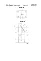
- FIG. 2 is a diagrammatic view showing the contour of the index elements of the color cathode ray tube.
- FIG. 3 is a diagrammatic view for illustrating the principle of the automatic convergence unit of the cathode ray tube.
- FIG. 4 is a chart for illustrating the composition of the paste employed for the formation of the index elements of the color cathode ray tube.
- the color cathode ray tube includes a tube-bulb 3 consisting of a panel section 1 as a display surface and a funnel section 2 continuous with the panel section 1.
- the tube-bulb 3 is formed of a transparent material, such as glass, and has an interior maintained substantially at a vacuum.
- An electron gun 4 as a means for producing cathode rays is provided in position within the tube-bulb 3.
- the gun 4 is so oriented that the cathode rays are directed to the phosphor surface formed on the inner surface of the panel section 1.
- a color-sensitive electrode 5 is placed parallel to and at a prescribed distance from the inner phosphor surface of the panel section 1.
- This color-selective electrode 5 is in the form of a thin plate formed with a predetermined large number of parallel slits.
- the electrode 5 is secured to a frame 6, and supported by suitable supporting means, not shown so that the aforementioned slits run parallel to the red(R), green(G) and blue(B) phosphor stripes making up the aforementioned phosphor surface.
- the color cathode ray tube is provided with a so-called automatic convergence system for correcting the color shift caused by relative shift of the arrival points of the three color rays at the color-selective electrode 5.
- index elements 9 are provided at a number of points on the reverse side of the electrode 5 facing to the electron gun 4, as shown in FIG. 2.
- the index element 9 is comprised of a vertical leg 10 orthogonal to the sweeping direction of the cathode rays indicated by the arrow mark H in FIG. 2 and a leg 11 inclined at a predetermined angle ⁇ relative to the sweeping direction.
- the index element 9 When the index element 9 is swept by the cathode rays, the element 9 emits the light.
- the cathode rays sweep the predetermined position as indicated by the arrow mark h 1 (FIG. 3), the distance between the vertical leg 10 and the inclined leg 11 on the sweeping trajectory has a predetermined length l 1 in FIG. 3.
- the arrow marks H and V in FIG. 3 indicate the horizontal and vertical directions on the display screen of the cathode ray tube.
- Such light emission occurring twice by the cathode rays sweeping the index element 9, is sensed by a sensor 8.
- the sensor 8 issues two pulses spaced by a time interval of l 1 /v as indicated by a waveform P 1 in FIG. 3.
- the sensor 8 issues two pulses spaced by a time interval l 2 /v as indicated by a waveform P 2 in FIG. 3.
- each of the three cathode rays is converged at one point on the color-selective electrode 5 to prevent color shift from occurring.
- the aforementioned index element 9 consists of preselected index phosphors, such as P46 and P47, an inorganic adhesive and water mixed together to a paste which is spray-coated in a predetermined pattern configuration on the aforementioned reverse surface of the color selective electrode 5 so as to be dried and cured.
- the sequence of operations for forming the index element 9 is as follows: a mask is secured by a magnet on the aforementioned reverse surface of the color-selective electrode 5 for masking the aforementioned predetermined pattern configuration.
- the color-selective electrode 5 is heated to about 110° C. by a constant temperature bath.
- the aforementioned paste is spray-coated by a sprayer on the color-selective electrode 5 from above the mask, after which the mask is removed.
- the paste remains affixed in the slits of the color-selective electrode 5
- the three cathode rays for displaying the image after the completion of the manufacture of the cathode ray tube are interrupted by the paste and cannot reach the phosphor surface, so that an optimum image cannot be produced.
- the aforementioned paste affixed to the slits and the surface of the color-selective electrode 5 is removed.
- the aforementioned inorganic adhesive contained in its paste is cured by a baking step in, for example, a frit sealing process of heating the color cathode ray tube in the entirety to an elevated temperature of 380° to 450° C., following the predetermined processing of the inside of the tube-bulb 3 inclusive of the color selective electrode 5, for affixing the index phosphor to the color-selective electrode 5.
- the paste composition is selected to satisfy the following formulas I to III;
- P denotes the weight of the index phosphor in grams
- M the weight of the inorganic adhesive in grams
- m the volume of the inorganic adhesive in milliliters
- w the volume of water in milliliters.
- the conditions governing the aforementioned paste composition may be represented by a region indicated A in FIG. 4.
- the total volume of the paste which is the sum of the volume of the inorganic adhesive and that of water, that is, (m+w) in the formulas (II) and (III), is set so as to be equal to 100 milliliters.
- the composition is represented by B in FIG. 4, the contents of the inorganic adhesive in the paste are reduced so that a sufficient adhesive force of the index element to the color-selective electrode 5 is not obtained.
- composition of the paste is such that, in connection with the formulas (II) and (III),
- the paste has an increased viscosity so that difficulties are presented in spray coating the composition by the spraying device.
- composition of the paste is such that, in connection with the formulas (II) and (III),
- the viscosity of the paste is lowered, while the total volume of the paste that is applied in order for the required amount of the index phosphor to be affixed to the color-selective electrode 5 is increased.
- the paste is spray coated on the aforementioned reverse surface of the color-selective electrode 5
- an increased amount of the paste flows into the slits and onto the surface of the electrode, so that difficulties are presented in forming the index elements 9 to a predetermined pattern configuration.
- the marks o, ⁇ , and in FIG. 4 are used for plotting the compositions according to the present invention and those of certain comparative examples, wherein the marks o, ⁇ , and respectively that both the adhesive force and the spraying operability are excellent; that the spraying operability is excellent but the adhesive force is insufficient; that the adhesive force is excellent but the spraying operability is inferior; and that both the adhesive force and the spraying operability are inferior.
- the paste coated on the electrode surface for producing the index elements in the preparation of the color cathode ray tube in accordance with the present invention is composed of the index phosphor, the inorganic adhesive and water, so that it is unnecessary to take precautions in ventilation and special separate ventilators are not required.
- the color cathode ray tube of the present invention is not limited to the above embodiments, but may be modified appropriately.
- the inorganic adhesive is not limited to the aforementioned monophix but any other inorganic adhesive may suitably be employed.
- the electron gun and the deflection coils are merely illustrative as the cathode ray emitting means and deflecting means and any other type of the cathode ray emitting and deflecting means may also be employed.
Landscapes
- Engineering & Computer Science (AREA)
- Multimedia (AREA)
- Signal Processing (AREA)
- Cathode-Ray Tubes And Fluorescent Screens For Display (AREA)
- Electrodes For Cathode-Ray Tubes (AREA)
Applications Claiming Priority (2)
| Application Number | Priority Date | Filing Date | Title |
|---|---|---|---|
| JP62-158517 | 1987-06-25 | ||
| JP62158517A JP2508444B2 (ja) | 1987-06-25 | 1987-06-25 | カラ−陰極線管 |
Publications (1)
| Publication Number | Publication Date |
|---|---|
| US4900983A true US4900983A (en) | 1990-02-13 |
Family
ID=15673472
Family Applications (1)
| Application Number | Title | Priority Date | Filing Date |
|---|---|---|---|
| US07/204,036 Expired - Lifetime US4900983A (en) | 1987-06-25 | 1988-06-08 | Cathode ray tube employing index phosphor elements adhered to a color selective electrode |
Country Status (4)
| Country | Link |
|---|---|
| US (1) | US4900983A (ja) |
| JP (1) | JP2508444B2 (ja) |
| KR (1) | KR970001590B1 (ja) |
| GB (1) | GB2206728B (ja) |
Cited By (1)
| Publication number | Priority date | Publication date | Assignee | Title |
|---|---|---|---|---|
| US20090015412A1 (en) * | 2005-07-19 | 2009-01-15 | Checkpoint Systems, Inc. | RFID Tags for Pallets and Cartons and System for Attaching Same |
Families Citing this family (2)
| Publication number | Priority date | Publication date | Assignee | Title |
|---|---|---|---|---|
| JPH0742562B2 (ja) * | 1989-08-22 | 1995-05-10 | 株式会社日立製作所 | 連続溶融金属めっき用ロール及びそれを用いた装置 |
| CN113874361A (zh) * | 2019-03-29 | 2021-12-31 | 医药生命融合研究团 | 具有抗癌活性的新型化合物及其制备方法 |
Citations (6)
| Publication number | Priority date | Publication date | Assignee | Title |
|---|---|---|---|---|
| GB519983A (en) * | 1938-10-07 | 1940-04-11 | Ronald Puleston | Improvements in or relating to conductive coatings employed in electron discharge devices |
| GB739371A (en) * | 1950-11-21 | 1955-10-26 | Gen Electric Co Ltd | Improvements in or relating to the deposition of adherent layers of powdered material on surfaces by a settling process |
| GB1308768A (en) * | 1970-06-22 | 1973-03-07 | Motorola Inc | Process for forming fine grain low noise luminescent screens |
| US4103069A (en) * | 1976-10-06 | 1978-07-25 | Gte Sylvania Incorporated | Coated silver activated zinc sulfide cathode ray tube |
| GB2102195A (en) * | 1981-07-06 | 1983-01-26 | Tektronix Inc | Feedback crt using a closed-loop beam position correction system |
| US4451504A (en) * | 1983-05-20 | 1984-05-29 | North American Philips Consumer Electronics Corp. | Process for applying phosphor to the aperture mask of a cathode ray tube |
-
1987
- 1987-06-25 JP JP62158517A patent/JP2508444B2/ja not_active Expired - Fee Related
-
1988
- 1988-06-08 US US07/204,036 patent/US4900983A/en not_active Expired - Lifetime
- 1988-06-16 GB GB8814313A patent/GB2206728B/en not_active Expired - Lifetime
- 1988-06-25 KR KR1019880007690A patent/KR970001590B1/ko not_active IP Right Cessation
Patent Citations (7)
| Publication number | Priority date | Publication date | Assignee | Title |
|---|---|---|---|---|
| GB519983A (en) * | 1938-10-07 | 1940-04-11 | Ronald Puleston | Improvements in or relating to conductive coatings employed in electron discharge devices |
| GB739371A (en) * | 1950-11-21 | 1955-10-26 | Gen Electric Co Ltd | Improvements in or relating to the deposition of adherent layers of powdered material on surfaces by a settling process |
| GB1308768A (en) * | 1970-06-22 | 1973-03-07 | Motorola Inc | Process for forming fine grain low noise luminescent screens |
| US4103069A (en) * | 1976-10-06 | 1978-07-25 | Gte Sylvania Incorporated | Coated silver activated zinc sulfide cathode ray tube |
| GB2102195A (en) * | 1981-07-06 | 1983-01-26 | Tektronix Inc | Feedback crt using a closed-loop beam position correction system |
| US4456853A (en) * | 1981-07-06 | 1984-06-26 | Tektronix, Inc. | Feedback CRT for use in a closed-loop correction system |
| US4451504A (en) * | 1983-05-20 | 1984-05-29 | North American Philips Consumer Electronics Corp. | Process for applying phosphor to the aperture mask of a cathode ray tube |
Cited By (2)
| Publication number | Priority date | Publication date | Assignee | Title |
|---|---|---|---|---|
| US20090015412A1 (en) * | 2005-07-19 | 2009-01-15 | Checkpoint Systems, Inc. | RFID Tags for Pallets and Cartons and System for Attaching Same |
| US7961102B2 (en) * | 2005-07-19 | 2011-06-14 | Checkpoint Systems, Inc. | RFID tags for pallets and cartons and system for attaching same |
Also Published As
| Publication number | Publication date |
|---|---|
| GB2206728A (en) | 1989-01-11 |
| JP2508444B2 (ja) | 1996-06-19 |
| GB8814313D0 (en) | 1988-07-20 |
| GB2206728B (en) | 1991-09-11 |
| KR890001143A (ko) | 1989-03-18 |
| KR970001590B1 (ko) | 1997-02-11 |
| JPS643942A (en) | 1989-01-09 |
Similar Documents
| Publication | Publication Date | Title |
|---|---|---|
| KR900004343B1 (ko) | 칼라수상관(受像管) | |
| JPS5825042A (ja) | 陰極線管 | |
| US4900983A (en) | Cathode ray tube employing index phosphor elements adhered to a color selective electrode | |
| US2727828A (en) | Method of making color-television screens | |
| EP0241087A3 (en) | Projection television system | |
| KR960000536B1 (ko) | 저항성의 접착성 프라이머 코팅층을 갖는 디스플레이 장치 및 그 제조 방법 | |
| US2936683A (en) | Cathode ray tube structure and process | |
| EP0738926A2 (en) | Photoresist for cathode ray tubes | |
| ES8607620A1 (es) | Un tubo de imagen en color | |
| GB713641A (en) | Improvements in or relating to cathode ray display tube apparatus | |
| US2879446A (en) | Electronic device | |
| KR920000757Y1 (ko) | 비임 난반사 방지용 브라운관 | |
| EP0163741A4 (en) | COLOR CATHODE RAY TUBE WITH BEAM INDEXING. | |
| EP0060647B1 (en) | Cathode ray tube phosphors | |
| US6891340B2 (en) | Tracking picture tube | |
| JPS5572347A (en) | Display device | |
| MY123760A (en) | Color cathode ray tube | |
| JPS6344861Y2 (ja) | ||
| WO2003005405A2 (en) | Cathode ray tube comprising an electron beam-control arrangement | |
| GB1467812A (en) | Cahtode ray tubes | |
| JPH0660833A (ja) | カラー陰極線管 | |
| JPS61185853A (ja) | 偏平カラ−ブラウン管 | |
| JPS5676149A (en) | Image tube | |
| JPS57119452A (en) | Cathode-ray tube for display light source | |
| JPS57208056A (en) | Cathode-ray tube for polychromatic display type light source |
Legal Events
| Date | Code | Title | Description |
|---|---|---|---|
| AS | Assignment |
Owner name: SONY CORPORATION, 7-35, KITASHINAGAWA-6, SHINAGAWA Free format text: ASSIGNMENT OF ASSIGNORS INTEREST.;ASSIGNORS:KATO, HIROSHI;MORI, HIROMASA;ISHIKAWA, YOSHIROU;REEL/FRAME:004905/0521 Effective date: 19880603 Owner name: SONY CORPORATION,JAPAN Free format text: ASSIGNMENT OF ASSIGNORS INTEREST;ASSIGNORS:KATO, HIROSHI;MORI, HIROMASA;ISHIKAWA, YOSHIROU;REEL/FRAME:004905/0521 Effective date: 19880603 |
|
| STCF | Information on status: patent grant |
Free format text: PATENTED CASE |
|
| FEPP | Fee payment procedure |
Free format text: PAYOR NUMBER ASSIGNED (ORIGINAL EVENT CODE: ASPN); ENTITY STATUS OF PATENT OWNER: LARGE ENTITY |
|
| FPAY | Fee payment |
Year of fee payment: 4 |
|
| FPAY | Fee payment |
Year of fee payment: 8 |
|
| FPAY | Fee payment |
Year of fee payment: 12 |