US4900974A - Ion source - Google Patents
Ion source Download PDFInfo
- Publication number
- US4900974A US4900974A US06/668,932 US66893284A US4900974A US 4900974 A US4900974 A US 4900974A US 66893284 A US66893284 A US 66893284A US 4900974 A US4900974 A US 4900974A
- Authority
- US
- United States
- Prior art keywords
- pointed end
- tip
- substance
- needle
- electric field
- Prior art date
- Legal status (The legal status is an assumption and is not a legal conclusion. Google has not performed a legal analysis and makes no representation as to the accuracy of the status listed.)
- Expired - Lifetime
Links
- 150000002500 ions Chemical class 0.000 claims abstract description 71
- 230000005684 electric field Effects 0.000 claims abstract description 33
- 239000000126 substance Substances 0.000 claims abstract description 27
- 239000007788 liquid Substances 0.000 claims description 10
- 238000010438 heat treatment Methods 0.000 claims description 7
- 230000000694 effects Effects 0.000 claims description 4
- 238000009736 wetting Methods 0.000 abstract description 3
- 229910052751 metal Inorganic materials 0.000 description 54
- 239000002184 metal Substances 0.000 description 54
- 238000010884 ion-beam technique Methods 0.000 description 11
- 238000010276 construction Methods 0.000 description 5
- WFKWXMTUELFFGS-UHFFFAOYSA-N tungsten Chemical compound [W] WFKWXMTUELFFGS-UHFFFAOYSA-N 0.000 description 5
- 230000007423 decrease Effects 0.000 description 4
- 150000002739 metals Chemical class 0.000 description 4
- 230000009471 action Effects 0.000 description 3
- 230000008859 change Effects 0.000 description 3
- 238000002474 experimental method Methods 0.000 description 3
- 229910052721 tungsten Inorganic materials 0.000 description 3
- 239000010937 tungsten Substances 0.000 description 3
- 230000015572 biosynthetic process Effects 0.000 description 2
- 239000000463 material Substances 0.000 description 2
- 229910001220 stainless steel Inorganic materials 0.000 description 2
- 239000010935 stainless steel Substances 0.000 description 2
- GYHNNYVSQQEPJS-UHFFFAOYSA-N Gallium Chemical compound [Ga] GYHNNYVSQQEPJS-UHFFFAOYSA-N 0.000 description 1
- 229910052797 bismuth Inorganic materials 0.000 description 1
- 238000006243 chemical reaction Methods 0.000 description 1
- 239000000470 constituent Substances 0.000 description 1
- 238000009795 derivation Methods 0.000 description 1
- 238000004141 dimensional analysis Methods 0.000 description 1
- 238000001312 dry etching Methods 0.000 description 1
- 230000002708 enhancing effect Effects 0.000 description 1
- 238000005530 etching Methods 0.000 description 1
- 238000000605 extraction Methods 0.000 description 1
- 229910052733 gallium Inorganic materials 0.000 description 1
- 229910052737 gold Inorganic materials 0.000 description 1
- 229910052738 indium Inorganic materials 0.000 description 1
- 238000002527 ion beam patterning Methods 0.000 description 1
- 238000002164 ion-beam lithography Methods 0.000 description 1
- 230000007246 mechanism Effects 0.000 description 1
- 238000002844 melting Methods 0.000 description 1
- 230000008018 melting Effects 0.000 description 1
- 229910052753 mercury Inorganic materials 0.000 description 1
- 238000000034 method Methods 0.000 description 1
- 230000008569 process Effects 0.000 description 1
- 238000005211 surface analysis Methods 0.000 description 1
Images

Classifications
-
- H—ELECTRICITY
- H01—ELECTRIC ELEMENTS
- H01J—ELECTRIC DISCHARGE TUBES OR DISCHARGE LAMPS
- H01J27/00—Ion beam tubes
- H01J27/02—Ion sources; Ion guns
- H01J27/26—Ion sources; Ion guns using surface ionisation, e.g. field effect ion sources, thermionic ion sources
Definitions
- the present invention relates to an improved ion source for use in for example an ion microanalyzer (IMA), an ion implanter, an ion beam patterning apparatus, a dry etching apparatus, etc.
- IMA ion microanalyzer
- ion implanter ion implanter
- ion beam patterning apparatus ion beam patterning apparatus
- dry etching apparatus ion beam patterning apparatus
- microminiaturization of an ion beam is required for enhancing performances in the fields of the dry microprocess such as for example ion beam lithography, dry development, and micro-doping, and submicron surface analysis such as, for example three-dimensional analysis including also the depth direction), etc. therefore considerable activity has been devoted to developing a point ion-source of high brightness.
- An ion source which has to properties of high brightness, small effective source-size, high angular intensity, and narrow energy width.
- An ion source which nearly satisfies the noted properties, is an electrohydrodynamic or "EHD" ion source.
- EHD ion source of the aforementioned type is described in detail in U.S. Pat. No. 4,088,919.
- the fundamental principle of the EHD ion source is based on the phenomenon that, when an intense electric field of 10 6 -10 8 V/cm is applied to a pointed end of an electrode formed as of a pipe having an inside diameter of approximately 100 ⁇ m filled a liquefied metal or a conductive liquid or a needle shaped electrode having a pointed end a radius of curvature of below several ⁇ m, wetted with a liquefied metal, ions of the liquid component are emitted therefrom.
- the mechanism of the ionization is not yet fully understood.
- FIG. 1 shows the fundamental construction of a prior-art EHD ion source of the needle type and according to this figure, an electrode generally designated by the reference numeral 10 provided with a tip 2 having a pointed end with a radius of curvature of below approximately 10 ⁇ m, is spot-welded to the central part of a hairpin-shaped filament 1.
- a central part 8 of the filament 1 carries a liquefied metal 3, for example, Ga.
- a high voltage V 1 is applied between an extractor 4, provided with an aperture 9 and disposed below the tip 2 and the electrode 10, by an extracting power supply 6 so as to give the extractor 4 a negative potential and to establish an electric field of 10 6 -10 8 V/cm at the pointed end of the tip 2.
- a voltage V o applied across both the ends of the filament 1 is a voltage for heating the filament 1 in order to keep the liquefied metal 3 in the liquefied state, and it is supplied by a heating power supply 7.
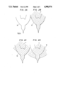
- FIGS. 2A-2D illustrate the manner in which the surface profile of the liquefied metal 3 carried on the central part 8 of the electrode 10 varies depending upon the magnitude of the extracting voltage V 1 . More particularly, as shown in FIG. 2A, the liquefied metal 3 is not carried by the electrode 10; however, in FIG. 2B the liquefied metal 3 is carried by the electrode 10, but the extracting voltage V 1 is null. As apparent from FIG. 2B, when the extracting voltage V 1 is null, the surface profile of the liquefied metal 3 extends substantially along the shape of the electrode 10. When the extracting voltage V 1 is gradually increased to 10 kV, the surface profile of the liquefied metal 3 is altered to the profile shown in FIG. 2C. As shown in FIG.
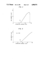
- FIG. 3 is a graph showing the relationship in the above experiment between the extracting voltage V 1 and the ion current I T obtained at that time.
- the ion current I T was measured with the extractor having no aperture 9 and by means of an ammeter disposed between the extractor 4 and ground.
- the electric field of the pointed end of the tip 2 increases with the increase of the extracting voltage V 1 .
- V t1 approximately 6.4 kV
- the ion beam 5 of the liquefied metal 3 begins to be emitted from the pointed end of the tip 2.
- the electric field is established to be the most intense at the pointed end of the tip 2.
- the liquefied metal 3 itself is drawn in the direction of the electric field.
- the field intensity is too high, not only is the liquid profile of the liquefied metal 3 changed from the previous conical shape into the flat shape as shown in FIG. 2D, but also the quantity of supply of the liquefied metal 3 towards the pointed end of the tip 2 becomes large.
- the quantity of the liquefied metal 3 at the pointed end of the tip 2 it is ideal that the quantity to be emitted as the ions 5 balances with the quantity to be supplied from the root part of the tip 2 to the pointed end thereof.
- the quantity supplied to the pointed end of the tip 2 is larger than the quantity emitted in the form of the ions 5 from the pointed end of the tip 2, the quantity of the liquefied metal 3 at the pointed end of the tip 2 becomes excessive. Therefore, the radius of curvature of the pointed end of the tip 2 becomes large, and the intensity of the electric field established at the pointed end of the tip 2 lowers.
- the ion current I T tends to increase with the increase of the extracting voltage V 1 , whereas, when the extracting voltage V 1 exceeds a certain value, the ion current I T tends to abruptly decrease in spite of the increase of the extracting voltage V 1 .
- the control of the magnitude of the ion current I T is made by the increase or decrease of the extracting voltage V 1 . Therefore, when it is intended to obtain a great ion current I T by applying a great extracting voltage V 1 , the electric field rather weakens due to the change of the shape of the pointed end of the tip 2, so that even when a voltage in excess of a certain specific value is applied a greater ion current cannot be generated. This leads to the problem that there is the limitation to the magnitude of the ion current I T which can be derived.
- an ion source is constructed in such a manner that a control electrode, which applies an electric field to a substance to-be-ionized held in its molten state by a holding part of an electrode and serves to control the quantity of supply of the substance to-be-ionized to a pointed end part of a tip, is disposed in the vicinity of the pointed end part of the tip separately from an extractor which serves to extract ions of the substance from the pointed end of the tip.
- the intensity of an electric field for supplying the pointed end of the tip with the substance to-be-ionized held in its molten state by the holding part of the electrode and the intensity of an electric field for deriving the ions of the substance from the pointed end of the tip can be controlled by voltages applied to the control electrode and the extractor, respectively and substantially independently of each other. It has therefore become possible to readily obtain a great ion current with a great extracting voltage without incurring the inconvenience that the ion current decreases suddenly when the extracting voltage is made high.
- FIG. 1 is a schematic view of a prior-art EHD ion source
- FIGS. 2A-2D are diagramatic illustrations, on an enlarged scale, of changes of the surface profile of a liquefied metal depending upon the magnitude of an extracting voltage, with the ion source of FIG. 1.
- FIG. 3 is a graph which shows the relationship between the extracting voltage and the ion current in the ion source shown in FIG. 1.
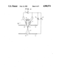
- FIG. 4 is a schematic view of an EHD ion source constructed according to the present invention.
- FIG. 5 is a graph which shows the relationship between the extracting voltage (control voltage) and the ion current in the construction of the ion source shown in FIG. 4, and
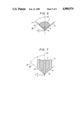
- FIGS. 6 and 7 are schematic views of other embodiments of an electrode in the ion source constructed according to the present invention.
- an ion source includes hairpin shaped 1 filament formed for example of a tungsten wire having a diameter of 150 ⁇ m.
- a tip 2 is spot-welded to the central or holding part 8 of the filament 1.
- the tip 2 is made of a tungsten wire having a diameter as 120 ⁇ m, and its pointed end is worked by the etching process into the shape of a needle having a radius of curvature of approximately 1 ⁇ m.
- a heating power supply 7 which has a voltage V o for energizing the filament 1 to control the temperature of the filament 1 to a certain fixed point of for example, 200° C., and to control the viscosity of the Ga metal 3 held by the central or holding part 8.
- the extractor 4 is disposed below the tip 2 in order to extract a Ga ion beam 5 from the pointed end of the tip 2 wetted with the Ga metal 3, by virtue of an electric field.
- An extracting voltage V 1 for extracting the Ga ion beam 5 is applied between the extractor 4 and the electrode 10 by an extracting power supply 6 so that the extractor 4 may have a negative potential.
- the aperture 9 provided in the extractor 4 enables the Ga ion beam 5 to pass through the extractor 4 and
- the aperture a is located so that a center line of the tip 2 may pass through a center of the aperture 9.
- a control electrode 11 is disposed in the vicinity of the pointed end of the tip 2 in order to supply the Ga metal 3 carried by the holding part 8 of the electrode 10 to the pointed end of the tip 2 in a suitable amount by an electric field, and which constitutes an important feature of this invention.
- a control voltage V 2 for supplying the pointed end of the tip 2 with the Ga metal 3 in the suitable amount is applied between the control electrode 11 and the electrode 10 by a control power supply 12 so that the control electrode 11 may have a negative potential.
- the control electrode 11 has an aperture 13, and is arranged so that the center line of the tip 2 may pass through the center of the aperture 13.
- the Ga metal 3, carried on the holding part 8 of the electrode 10, is heated to approximately 200° C. by the filament 1 heated by the heating voltage V o .
- the control voltage V 2 is null
- the Ga metal 3 wets the surface of the tip 2 in a manner to center around the root part of the tip 2.
- the extent of the wetting at this time is determined by the viscosity, surface tension, etc. of the Ga metal 3.
- the Ga metal 3 is not considered to sufficiently reach the vicinity of the pointed end of the tip 2 having the radius of curvature of approximately 1 ⁇ m.
- the control voltage V 2 is applied between the electrode 10 and the control electrode 11 by the control power supply 12, an electric field is established on the surface of the Ga metal 3.
- This electric field acts to draw the Ga metal 3 towards the pointed end of the tip 2 along the surface of the tip 2.
- the Ga metal 3 not having reached the vicinity of the pointed end of the tip 2 at the null control voltage V 2 reaches the vicinity of the pointed end of the tip 2 and can wet the pointed end upon the application of the control voltage V 2 .
- the magnitude of the control voltage V 2 it is possible to freely control the quantity in which the Ga metal 3 wets the pointed end of the tip 2, that is, the quantity of supply of the Ga metal 3 to the pointed end of the tip 2.
- the extracting voltage V 1 is applied between the extractor 4 and the electrode 10 by the extracting power supply 6, an intense electric field which is principally determined by the extracting voltage V 1 is established at the pointed end of the tip 2. This electric field acts on the surface of the Ga metal 3 and emits the Ga ion beam 5 of the Ga metal 3 from the pointed end of the tip 2.
- the ion current I T was measured by means of an ammeter disposed between the extractor 4 and the ground, with the extractor 4 having no aperture 9.
- the field intensity established at the pointed end of the tip 2 increases with the increase of the extracting voltage V 1 , and, at the time when a certain threshold value V t2 (approximately 8 kV) is exceeded, the Ga ion beam 5 begins to be emitted from the pointed end of the tip 2.
- the ion current I T increases with the increase of the extracting voltage V 1 in substantial proportion to the extracting voltage V 1 .
- the control voltage V 2 at this time lies in a range of 1-3 kV.
- the Ga metal 3 can be supplied to the pointed end part of the tip 2 in a suitable amount by controlling the control voltage V 2 . That is, the radius of curvature of the pointed end of the tip 2 in the state in which the end is wetted with the Ga metal 3 is always maintained in the optimum range, and any great change in the field intensity established in the pointed end part of the tip 2 does not develop due to the increase of the radius of curvature.
- the ion current I T corresponding to the value of the extracting voltage V 1 can be generated from the pointed end of the tip 2 without being limited by the magnitude of the extracting voltage V 1 .
- the graph in FIG. 5 obtained under conditions stated below.
- the electrode 10 used was the same as stated previously.
- a stainless steel sheet was used as the control electrode 11 with the sheet having an outside diameter of 40 mm aperture 13 of 1 mm, and 0.5 mm a thickness of.
- the control electrode 11 had its center aligned with the center axis of the tip 2, and was horizontally installed of a position of 0.5 mm from the pointed end of the tip 2 towards the root part of the tip 2.
- the extractor 4 was installed at position of 2 mm from the pointed end of the tip 2 downwards.
- the installed position of the control electrode 11 is not restricted to the above-noted position, but ion sources functioned substantially similarly to the above-stated ion source in the following range. That is, under the state under which the control electrode 11 is held horizontal with the center of the control electrode 11 aligned with the center axis of the tip 2, the permissible distance from the pointed end of the tip 2 onto the root side of the tip 2 is at most 2 mm irrespective of the size of the bore corresponding to the aperture 13. In addition, the permissible distance from the pointed end of the tip 2 onto the side of the extractor 4 is determined by the bore corresponding to the aperture 13, and the range thereof is at most the bore corresponding to the aperture 13.
- the optimum surface profile which is to be formed by the Ga metal 3 carried by the holding part 8 of the electrode 10 is the conical shape.
- G. Taylor it has been theoretically conjectured by G. Taylor that when the half apical angle of the cone is 49.3°, the stability of the ion current I T which can be derived is the highest (this cone is called the "Taylor Cone", and is described in detail in Proc. Roy. Soc. (London) A280 (1964) 383 by G. Taylor).
- electrode generally designated by the reference numeral 20 which is adapted to enable a formation of the above-noted Taylor cone can be formed between the holding part 8 for the liquefied metal 3 and the pointed end of a tip 15.
- the tip 15 having a needle-shape pointed end with a diameter of 120 ⁇ m, is spot-welded to the central part of a filament 14 which is formed into the conical shape and which has a diameter of 150 ⁇ m.
- the positional relationship between the filament 14 and the tip 15 is as stated below.
- the pointed end of the tip 15 is somewhat protuberant beyond the point at which the tangent 17 to the side line 16 of the filament 14 intersects with the center line 18 of the tip 15, in other words, the apex of the cone, and that the distance of the protuberance d lies in a range of at most 1 mm.
- the electrode 20 By constructing the electrode 20 in this manner, the surface profile of the liquefied metals such as Ga carried on the holding part 8 forms the Taylor cone without fail. As a result, the electrode 20 for example, could reduce the variation-versus-time of the ion current to about 5% from about 30% of the previous electrode in which the positional relationship between the filament and the tip does not meet the relationship specified above. As conditions at this time, Ga was used as the liquefied metals, a voltage of 13 kV was applied as the extracting voltage, and the average value of the ion current was made approximately 8 ⁇ A.
- the "variation-versus-time” signifies the percentage obtained in such a way that a minute variation in the ion current fluctuating in a short time is divided by the average ion current, the quotient being multiplied by 100.
- the reason why the variation-versus-time could be sharply reduced in comparison with that in the prior art is conjectured as follows.
- the electrode 20 of the present embodiment has the electrode construction in which the Taylor cone is prone to be stably formed, so that the electrode will be capable of stably maintaining the Taylor cone even in case of some changes in the conditions.
- an electrode generally designated by the reference numeral 30 is provided Taylor cone which is also adapted to enable a formation of the above-noted between a holding part 19 for the liquefied metal 3 and the pointed end of a needle 25.
- the electrode 30 includes a pipe 21, made of tungsten or stainless steel, having one end is drawn into the shape of a cone and with an outside diameter of 1 mm and a wall thickness of 0.2 mm, and a needle 25 which is made of tungsten.
- the needle 25 has a end with pointed a diameter of 500 ⁇ m.
- the pipe 21 and needle 25 are located so that a center line 22 of the needle 25 passes through the center of the pipe 21.
- the pointed end of the needle 25 is slightly protuberant from the conically shaped end of the pipe 21.
- the positional relation between the pipe 21 and the needle 25 is as stated below.
- the half apical angle ⁇ of the cone, formed in such a manner that a tangent 24 to the side line 23 of the pipe 21 intersects with the center line 22 of the needle 25, lies in a range of 35°-55°.
- it is desirable that the pointed end of the needle 25 is somewhat protuberant beyond the point at which the tangent 24 to the side line 23 of the pipe 21 intersects with the center line 22 of the needle 25, in other words, the apex of the cone, and that the distance of the protuberance d lies in a range of at most 1 mm.
- the electrode 30 By constructing the electrode 30 in this manner, the surface profile of the liquefied metals such as Ga carried on the holding part 19 forms the Taylor cone without fail. As a result, the electrode 30 for example, could reduce the variation-versus-time of the ion current to about 5% from about 30% of the previous electrode in which the positional relation between the pipe and the needle does not meet the relation specified above. As conditions at this time, Ga was used as the liquefied metal 3, a voltage of 13 kV was applied as the extracting voltage, and the average value of the ion current was made approximately 8 ⁇ A. It has been experimentally revealed that further decreases in the variations-versus-time in the foregoing electrodes 20 and 30 can be achieved by heating the filament 14, the pipe 21 and the needle 25 so as to maintain the liquefied metal 3 at the optimum temperature.
- Ga has been referred to as the liquid substance to be ionized
- metals such as Au, Hg, In and Bi and non-metallic conductive substances can be similarly treated.
- they may present liquefied conditions in the states in which ions are derived, and this requisite can be achieved with heating means.
- tungsten has been referred to as the constituent material of the electrodes, it is not restrictive, but any other material may well be employed as long as it has a high melting point and it does not cause a chemical reaction with the liquefied substance.
- control voltage V 2 need not always be applied so as to afford the negative potential to the control electrode 11, but it may well be applied reversely because the effect of the action of the electric field on the liquefied surface is identical. In this case, however, the direction of the intensity influential on the electric field of the pointed end of the tip 2 becomes the opposite.
Landscapes
- Chemical & Material Sciences (AREA)
- Engineering & Computer Science (AREA)
- Combustion & Propulsion (AREA)
- Electron Sources, Ion Sources (AREA)
- Electron Beam Exposure (AREA)
Applications Claiming Priority (2)
| Application Number | Priority Date | Filing Date | Title |
|---|---|---|---|
| JP55-13724 | 1980-02-08 | ||
| JP1372480A JPS56112058A (en) | 1980-02-08 | 1980-02-08 | High brightness ion source |
Related Parent Applications (1)
| Application Number | Title | Priority Date | Filing Date |
|---|---|---|---|
| US06533745 Continuation | 1983-09-19 |
Publications (1)
| Publication Number | Publication Date |
|---|---|
| US4900974A true US4900974A (en) | 1990-02-13 |
Family
ID=11841190
Family Applications (1)
| Application Number | Title | Priority Date | Filing Date |
|---|---|---|---|
| US06/668,932 Expired - Lifetime US4900974A (en) | 1980-02-08 | 1984-11-07 | Ion source |
Country Status (4)
| Country | Link |
|---|---|
| US (1) | US4900974A (de) |
| EP (1) | EP0037455B1 (de) |
| JP (1) | JPS56112058A (de) |
| DE (1) | DE3167131D1 (de) |
Cited By (1)
| Publication number | Priority date | Publication date | Assignee | Title |
|---|---|---|---|---|
| WO2013090583A1 (en) * | 2011-12-15 | 2013-06-20 | Academia Sinica | Periodic field differential mobility analyzer |
Families Citing this family (13)
| Publication number | Priority date | Publication date | Assignee | Title |
|---|---|---|---|---|
| JPS5873947A (ja) * | 1981-10-26 | 1983-05-04 | Jeol Ltd | イオン銃 |
| JPS5878557U (ja) * | 1981-11-24 | 1983-05-27 | 株式会社日立製作所 | 電界放出型イオン源 |
| JPS5895233U (ja) * | 1981-12-21 | 1983-06-28 | 日本電子株式会社 | 液体金属イオン源 |
| US4577135A (en) * | 1982-02-22 | 1986-03-18 | United Kingdom Atomic Energy Authority | Liquid metal ion sources |
| JPS58169761A (ja) * | 1982-03-30 | 1983-10-06 | Jeol Ltd | 電界放出型イオンビ−ム発生装置 |
| JPS58225537A (ja) * | 1982-06-25 | 1983-12-27 | Hitachi Ltd | イオン源装置 |
| JPS59165356A (ja) * | 1983-03-09 | 1984-09-18 | Hitachi Ltd | イオン源 |
| JPS61211937A (ja) * | 1985-11-15 | 1986-09-20 | Hitachi Ltd | 電界放出型イオン源 |
| JP2528859B2 (ja) * | 1987-02-27 | 1996-08-28 | 株式会社日立製作所 | 荷電粒子源 |
| US5034612A (en) * | 1989-05-26 | 1991-07-23 | Micrion Corporation | Ion source method and apparatus |
| ATE121563T1 (de) * | 1989-05-26 | 1995-05-15 | Micrion Corp | Herstellungsverfahren und vorrichtung für ionenquelle. |
| US6914386B2 (en) * | 2003-06-20 | 2005-07-05 | Applied Materials Israel, Ltd. | Source of liquid metal ions and a method for controlling the source |
| EP1622184B1 (de) * | 2004-07-28 | 2011-05-18 | ICT Integrated Circuit Testing Gesellschaft für Halbleiterprüftechnik mbH | Emitter für eine Ionenquelle und Verfahren zu deren Herstellung |
Citations (2)
| Publication number | Priority date | Publication date | Assignee | Title |
|---|---|---|---|---|
| US3814975A (en) * | 1969-08-06 | 1974-06-04 | Gen Electric | Electron emission system |
| US4088919A (en) * | 1976-04-13 | 1978-05-09 | United Kingdom Atomic Energy Authority | Ion source including a pointed solid electrode and reservoir of liquid material |
Family Cites Families (1)
| Publication number | Priority date | Publication date | Assignee | Title |
|---|---|---|---|---|
| JPS5831698B2 (ja) * | 1980-01-18 | 1983-07-07 | 工業技術院長 | 電界蒸発型イオンビ−ム発生装置 |
-
1980
- 1980-02-08 JP JP1372480A patent/JPS56112058A/ja active Pending
-
1981
- 1981-02-06 DE DE8181100861T patent/DE3167131D1/de not_active Expired
- 1981-02-06 EP EP81100861A patent/EP0037455B1/de not_active Expired
-
1984
- 1984-11-07 US US06/668,932 patent/US4900974A/en not_active Expired - Lifetime
Patent Citations (2)
| Publication number | Priority date | Publication date | Assignee | Title |
|---|---|---|---|---|
| US3814975A (en) * | 1969-08-06 | 1974-06-04 | Gen Electric | Electron emission system |
| US4088919A (en) * | 1976-04-13 | 1978-05-09 | United Kingdom Atomic Energy Authority | Ion source including a pointed solid electrode and reservoir of liquid material |
Cited By (2)
| Publication number | Priority date | Publication date | Assignee | Title |
|---|---|---|---|---|
| WO2013090583A1 (en) * | 2011-12-15 | 2013-06-20 | Academia Sinica | Periodic field differential mobility analyzer |
| US9324552B2 (en) | 2011-12-15 | 2016-04-26 | Academia Sinica | Periodic field differential mobility analyzer |
Also Published As
| Publication number | Publication date |
|---|---|
| DE3167131D1 (en) | 1984-12-20 |
| EP0037455B1 (de) | 1984-11-14 |
| EP0037455A2 (de) | 1981-10-14 |
| JPS56112058A (en) | 1981-09-04 |
| EP0037455A3 (en) | 1982-08-04 |
Similar Documents
| Publication | Publication Date | Title |
|---|---|---|
| US4900974A (en) | Ion source | |
| US4088919A (en) | Ion source including a pointed solid electrode and reservoir of liquid material | |
| US4426582A (en) | Charged particle beam apparatus and method utilizing liquid metal field ionization source and asymmetric three element lens system | |
| Brodie | Studies of field emission and electrical breakdown between extended nickel surfaces in vacuum | |
| US4488045A (en) | Metal ion source | |
| Bell et al. | The influence of substrate geometry on the emission properties of a liquid metal ion source | |
| DE1515295B1 (de) | Vorrichtung zum Aufbringen dünner Schichten aus dem Material einer Zerstäubungskathode auf eine senkrecht zu einer Anode angeordnete Unterlage | |
| US4567398A (en) | Liquid metal ion source | |
| Ishikawa et al. | Impregnated‐electrode‐type liquid metal ion source | |
| US4551650A (en) | Field-emission ion source with spiral shaped filament heater | |
| JP2807719B2 (ja) | 集束イオンビーム装置の液体金属イオン源の動作方法 | |
| US5936251A (en) | Liquid metal ion source | |
| JPS58163135A (ja) | イオン源 | |
| JP3058785B2 (ja) | エミッタ製造方法 | |
| US4246481A (en) | Contact ionization apparatus | |
| Komuro et al. | Field‐emission liquid‐metal ion source and triode ion gun | |
| JPH1064438A (ja) | 液体金属イオン源 | |
| JPS6129041A (ja) | 電界放出形液体金属イオン源 | |
| Swanson et al. | The influence of electrode geometry on liquid metal ion source performance | |
| RU2075132C1 (ru) | Источник интенсивных ионных пучков | |
| Czarczynski et al. | Liquid metal ion sources | |
| JPS58137943A (ja) | イオン源 | |
| JPH0369137B2 (de) | ||
| JPS6151725A (ja) | 電界放射型陰極 | |
| JPH0160891B2 (de) |
Legal Events
| Date | Code | Title | Description |
|---|---|---|---|
| AS | Assignment |
Owner name: HITACHI, LTD., JAPAN Free format text: ASSIGNMENT OF ASSIGNORS INTEREST.;ASSIGNORS:ISHITANI, TOHRU;TODOKORO, HIDEO;TAMURA, HIFUMI;REEL/FRAME:005139/0383 Effective date: 19810108 |
|
| STCF | Information on status: patent grant |
Free format text: PATENTED CASE |
|
| FEPP | Fee payment procedure |
Free format text: PAYOR NUMBER ASSIGNED (ORIGINAL EVENT CODE: ASPN); ENTITY STATUS OF PATENT OWNER: LARGE ENTITY |
|
| FPAY | Fee payment |
Year of fee payment: 4 |
|
| FPAY | Fee payment |
Year of fee payment: 8 |
|
| FPAY | Fee payment |
Year of fee payment: 12 |