US4900237A - Rolling rotor motor balancing means - Google Patents
Rolling rotor motor balancing means Download PDFInfo
- Publication number
- US4900237A US4900237A US07/266,425 US26642588A US4900237A US 4900237 A US4900237 A US 4900237A US 26642588 A US26642588 A US 26642588A US 4900237 A US4900237 A US 4900237A
- Authority
- US
- United States
- Prior art keywords
- rotor
- shafts
- pair
- rolling
- rolling rotor
- Prior art date
- Legal status (The legal status is an assumption and is not a legal conclusion. Google has not performed a legal analysis and makes no representation as to the accuracy of the status listed.)
- Expired - Fee Related
Links
- 238000005096 rolling process Methods 0.000 title claims abstract description 31
- 238000004804 winding Methods 0.000 claims description 16
- 239000007788 liquid Substances 0.000 abstract description 4
- 238000007906 compression Methods 0.000 description 4
- 230000006835 compression Effects 0.000 description 3
- 239000000463 material Substances 0.000 description 2
- 239000003507 refrigerant Substances 0.000 description 2
- 238000005057 refrigeration Methods 0.000 description 2
- 230000004913 activation Effects 0.000 description 1
- 238000010586 diagram Methods 0.000 description 1
- 230000005484 gravity Effects 0.000 description 1
- 230000006698 induction Effects 0.000 description 1
- 238000007789 sealing Methods 0.000 description 1
- 238000003466 welding Methods 0.000 description 1
Images
Classifications
-
- H—ELECTRICITY
- H02—GENERATION; CONVERSION OR DISTRIBUTION OF ELECTRIC POWER
- H02K—DYNAMO-ELECTRIC MACHINES
- H02K27/00—AC commutator motors or generators having mechanical commutator
- H02K27/30—Structural association with auxiliary mechanical devices, e.g. with clutches or brakes
-
- F—MECHANICAL ENGINEERING; LIGHTING; HEATING; WEAPONS; BLASTING
- F04—POSITIVE - DISPLACEMENT MACHINES FOR LIQUIDS; PUMPS FOR LIQUIDS OR ELASTIC FLUIDS
- F04C—ROTARY-PISTON, OR OSCILLATING-PISTON, POSITIVE-DISPLACEMENT MACHINES FOR LIQUIDS; ROTARY-PISTON, OR OSCILLATING-PISTON, POSITIVE-DISPLACEMENT PUMPS
- F04C29/00—Component parts, details or accessories of pumps or pumping installations, not provided for in groups F04C18/00 - F04C28/00
- F04C29/0042—Driving elements, brakes, couplings, transmissions specially adapted for pumps
- F04C29/0085—Prime movers
-
- H—ELECTRICITY
- H02—GENERATION; CONVERSION OR DISTRIBUTION OF ELECTRIC POWER
- H02K—DYNAMO-ELECTRIC MACHINES
- H02K29/00—Motors or generators having non-mechanical commutating devices, e.g. discharge tubes or semiconductor devices
-
- H—ELECTRICITY
- H02—GENERATION; CONVERSION OR DISTRIBUTION OF ELECTRIC POWER
- H02K—DYNAMO-ELECTRIC MACHINES
- H02K41/00—Propulsion systems in which a rigid body is moved along a path due to dynamo-electric interaction between the body and a magnetic field travelling along the path
- H02K41/06—Rolling motors, i.e. motors having the rotor axis parallel to the stator axis and following a circular path as the rotor rolls around the inside or outside of the stator ; Nutating motors, i.e. having the rotor axis parallel to the stator axis inclined with respect to the stator axis and performing a nutational movement as the rotor rolls on the stator
Definitions
- a rolling rotor motor is one in which only a portion of the windings are activated at any given time and the resultant asymmetric magnetic field is moved around the stator by changing which ones of the windings are the activated windings.
- This type of motor is characterized by high torque and low speed.
- the rotor is located internally of the stator, the coaction between the rotor and stator as a result of the asymmetric magnetic field, unless otherwise limited, is like that of the piston and cylinder of a rolling piston or reciprocating vane type compressor.
- the rotor may also be the piston of a rolling piston compressor such as is disclosed in U.S. Pat. No. 2,561,890. Since the rotor rolls around the stator, there are low bearing loads as compared to a motor in which the rotor is constrained to rotate about a fixed axis.
- the rolling rotor motor can be integral with the compressor thereby reducing the size and number of parts such as shafts and bearings, but it has some inherent disadvantages. Because only some of the windings are activated at any particular time, the output torque per pound of motor weight is less than it would be for an induction motor. Also, the rotor is dynamically unbalanced since its center traces a circular orbit as it moves circumferentially towards the activated windings due to magnetic attraction as it follows the rotating field. The unbalance forces increase with the square of the rotor speed thus making the motor unsuitable for high speed applications.
- a short axial shaft is provided on each end of the rolling rotor and serves as a bearing surface for mounting a counterweight.
- Short shafts on the end frames serve to constrain the counterweights so that their masses are always located diametrically opposite the rotor mass relative to their rotational center line defined by the short shafts on the end frame.
- the drive for each of the counterweights is a pin in a slot, so that the counterweights maintain angular alignment.
- the rotor is free to change its radius of operation such as rolling over foreign material on the inside of the stator or a liquid slug when used as a compressor.
- the center of the rotor of a rolling rotor motor and a counterweight are located on diametrically opposite sides of the short shafts on the end frame.
- the rotor alone or the rotor and counterweight are able to move radially to change their rotation arm and thereby accommodate foreign/incompressible material at the point of contact between the rotor and stator.
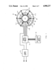
- FIG. 1 is a circuit diagram for a rolling rotor motor/compressor
- FIG. 2 is a more detailed view of the switching portion of the circuit of FIG. 1;
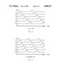
- FIG. 3 is a graph showing the actuation of the switches as a function of time in the on at off mode
- FIG. 4 is a graph showing the actuation of the switches as a function of time in the on before off mode
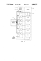
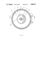
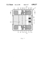
- FIG. 5 is a vertical section of a rolling rotor motor/compressor taken along line 5--5 of FIG. 6;
- FIG. 6 is a horizontal section taken along line 6--6 of FIG. 5;
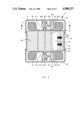
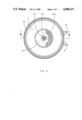
- FIG. 7 is a vertical section of a modified rolling rotor motor/compressor taken along line 7--7 of FIG. 8;
- FIG. 8 is a horizontal section taken along line 8--8 of FIG. 7.
- the numeral 10 generally designates a rolling rotor motor/compressor which has a plurality of windings with six, 11-1 to 6, being illustrated.
- Power from power supply 12 is supplied to windings 11-1 to 6 by power switch module 14 under the control of switching logic module 16.
- the power supply 12 is connected to windings 11-1 to 6 through switches 14-1 to 6 which are controlled by switching logic module 16.
- Switch 14-1 is illustrated as solenoid actuated but any suitable power switching may be employed.
- Switches 14-1 to 6, as illustrated in FIG. 3 can be actuated in an "on at off" mode wherein the shutting off of power to one winding coincides with the supplying of power to the next winding.
- switches 14-1 to 6 can be actuated in an "on before off” mode wherein power is supplied to a winding for a short period of time after power is supplied to the next winding.
- the numeral 10 generally designates a rolling rotor motor/compressor which includes a stator 20 with a base 20-1 and windings 11, and a rotor/piston 21 having short axial shafts 21-1 and 2.
- Rotor/piston 21 and bore 20-1 together define a lunette shaped space or chamber 28 during operation.
- Space or chamber 28 defines the air gap of the motor and the suction and/or discharge chamber of the compressor.
- Short shafts 21-1 and 2 are rotatably received in bores 30-1 and 40-1, respectively of counterweights 30 and 40.
- End frames 24 and 26 define the top and bottom, respectively, of hermetic shell 22 and have axial shafts 24-1 and 26-1 and provide a chamber for counterweights 30 and 40, respectively.
- Axial shafts 24-1 and 26-1 coact with slots 30-2 and 40-2 to provide a pivot for the rotor 21 and counterweights 30 and 40 while permittinq radial movement of the rotor 21 and counterweights 30 and 40 as a unit.
- rotor/piston 21 In operation, as the magnetic field moves about the stator 20 through the selective activation of some of the windings, as described above, rotor/piston 21 tends to follow the magnetic field and coacts with the base 20-1 of stator 20 in the manner of the coaction of the piston and cylinder of a rolling piston compressor.
- the rotor/piston 21 thus rotates about the coaxial axes of shafts 21-1 and 2 while the rotor/piston 21 and counterweights 30 and 40 rotate as a unit about coaxial axes of shafts 24-1 and 26-1.
- the unit can be dynamically balanced with the correct selection or design of the counterweights 30 and 40 using standard moment of inertia equations to balance the rotor/piston 21 with the counterweights 30 and 40. Since the gas loads change with the compression process, there will be unbalance at some time since the counterweights do not accommodate these changes. However, the initial selection of the counterweight can chose some stage of the compression stroke at which balance is established. If a liquid slug, for example, was in the trapped volume of the compressor, its incompressibility would create an excess pressure.
- rotor/piston 21 can move away from the wall of base 20-1 of stator 20 thereby unsealing the trapped volume and permitting the rotor/piston 21 to override the liquid slug, grit, etc.
- the rolling rotor motor/compressor 10' of FIGS. 7 and 8 is structurally identical to the rolling rotor motor/compressor 10 of FIGS. 1-6 except in the details of counterweights 130 and 140.
- the counterweights 30 and 40 do not have a fixed axis of rotation whereas counterweights 130 and 140 do.
- counterweights 130 and 140 have bores 130-2 and 140-2 which receive and rotate about axial shafts 24-1 and 26-1.
- Short shafts 21-1 and 2 are received in slots 130-1 and 140-1 which permit radial movement of rotor/piston 21 without requiring movement of weight portions 130-3 and 140-3 rather than radial movement of both the rotor/piston 21 and the counterweights 30 and 40 as in the case of motor/compressor 10.
Landscapes
- Engineering & Computer Science (AREA)
- Power Engineering (AREA)
- Physics & Mathematics (AREA)
- Chemical & Material Sciences (AREA)
- Combustion & Propulsion (AREA)
- Electromagnetism (AREA)
- Mechanical Engineering (AREA)
- General Engineering & Computer Science (AREA)
- Connection Of Motors, Electrical Generators, Mechanical Devices, And The Like (AREA)
- Brushless Motors (AREA)
- Linear Motors (AREA)
- Applications Or Details Of Rotary Compressors (AREA)
Priority Applications (5)
| Application Number | Priority Date | Filing Date | Title |
|---|---|---|---|
| US07/266,425 US4900237A (en) | 1988-11-02 | 1988-11-02 | Rolling rotor motor balancing means |
| JP1284664A JPH06101921B2 (ja) | 1988-11-02 | 1989-10-31 | ローリングロータ型モータ |
| BR898905620A BR8905620A (pt) | 1988-11-02 | 1989-11-01 | Dispositivos de balanceamento de motor de rotor de rolamento |
| KR1019890015792A KR920000686B1 (ko) | 1988-11-02 | 1989-11-01 | 로울링 로우터 모터 균형 장치 |
| IT02224789A IT1237677B (it) | 1988-11-02 | 1989-11-02 | Dispositivo di bilanciamento per motore elettrico con rotore a rotolamento. |
Applications Claiming Priority (1)
| Application Number | Priority Date | Filing Date | Title |
|---|---|---|---|
| US07/266,425 US4900237A (en) | 1988-11-02 | 1988-11-02 | Rolling rotor motor balancing means |
Publications (1)
| Publication Number | Publication Date |
|---|---|
| US4900237A true US4900237A (en) | 1990-02-13 |
Family
ID=23014542
Family Applications (1)
| Application Number | Title | Priority Date | Filing Date |
|---|---|---|---|
| US07/266,425 Expired - Fee Related US4900237A (en) | 1988-11-02 | 1988-11-02 | Rolling rotor motor balancing means |
Country Status (5)
| Country | Link |
|---|---|
| US (1) | US4900237A (it) |
| JP (1) | JPH06101921B2 (it) |
| KR (1) | KR920000686B1 (it) |
| BR (1) | BR8905620A (it) |
| IT (1) | IT1237677B (it) |
Cited By (8)
| Publication number | Priority date | Publication date | Assignee | Title |
|---|---|---|---|---|
| DE4118950A1 (de) * | 1991-06-08 | 1993-02-11 | Teves Gmbh Alfred | Antriebsaggregat, insbesondere motorpumpenaggregat |
| NL1013535C2 (nl) * | 1999-11-09 | 2001-05-11 | Stichting Energie | Windturbine-generatorsamenstel. |
| US6287092B1 (en) * | 1998-03-11 | 2001-09-11 | Tecumseh Products Company | Counterweight for hermetic compressors |
| US6351043B1 (en) * | 1999-07-02 | 2002-02-26 | Interelectric Ag | Dynamically balanced small electric motor |
| US20050031465A1 (en) * | 2003-08-07 | 2005-02-10 | Dreiman Nelik I. | Compact rotary compressor |
| US20050201884A1 (en) * | 2004-03-09 | 2005-09-15 | Dreiman Nelik I. | Compact rotary compressor with carbon dioxide as working fluid |
| US20060159570A1 (en) * | 2005-01-18 | 2006-07-20 | Manole Dan M | Rotary compressor having a discharge valve |
| US20200307778A1 (en) * | 2019-03-28 | 2020-10-01 | Nidec Corporation | Motor, rotor device, and drone |
Families Citing this family (2)
| Publication number | Priority date | Publication date | Assignee | Title |
|---|---|---|---|---|
| US9325218B2 (en) | 2011-07-06 | 2016-04-26 | General Electric Company | Laminated rotor balancing provisions |
| WO2013006079A1 (en) | 2011-07-06 | 2013-01-10 | General Electric Company | Laminated rotor machining enhancement |
Citations (3)
| Publication number | Priority date | Publication date | Assignee | Title |
|---|---|---|---|---|
| US2480825A (en) * | 1945-06-29 | 1949-09-06 | Vibro Plus Corp | Electric vibration motor |
| US2561890A (en) * | 1945-07-25 | 1951-07-24 | George C Stoddard | Dynamoelectric machine |
| JPS5622553A (en) * | 1979-07-31 | 1981-03-03 | Masakado Ejima | Variable vibration motor |
-
1988
- 1988-11-02 US US07/266,425 patent/US4900237A/en not_active Expired - Fee Related
-
1989
- 1989-10-31 JP JP1284664A patent/JPH06101921B2/ja not_active Expired - Lifetime
- 1989-11-01 KR KR1019890015792A patent/KR920000686B1/ko not_active IP Right Cessation
- 1989-11-01 BR BR898905620A patent/BR8905620A/pt unknown
- 1989-11-02 IT IT02224789A patent/IT1237677B/it active IP Right Grant
Patent Citations (3)
| Publication number | Priority date | Publication date | Assignee | Title |
|---|---|---|---|---|
| US2480825A (en) * | 1945-06-29 | 1949-09-06 | Vibro Plus Corp | Electric vibration motor |
| US2561890A (en) * | 1945-07-25 | 1951-07-24 | George C Stoddard | Dynamoelectric machine |
| JPS5622553A (en) * | 1979-07-31 | 1981-03-03 | Masakado Ejima | Variable vibration motor |
Cited By (12)
| Publication number | Priority date | Publication date | Assignee | Title |
|---|---|---|---|---|
| DE4118950A1 (de) * | 1991-06-08 | 1993-02-11 | Teves Gmbh Alfred | Antriebsaggregat, insbesondere motorpumpenaggregat |
| US6287092B1 (en) * | 1998-03-11 | 2001-09-11 | Tecumseh Products Company | Counterweight for hermetic compressors |
| US6351043B1 (en) * | 1999-07-02 | 2002-02-26 | Interelectric Ag | Dynamically balanced small electric motor |
| NL1013535C2 (nl) * | 1999-11-09 | 2001-05-11 | Stichting Energie | Windturbine-generatorsamenstel. |
| WO2001035517A1 (en) * | 1999-11-09 | 2001-05-17 | Stichting Energieonderzoek Centrum Nederland | Wind turbine/generator assembly |
| US20050031465A1 (en) * | 2003-08-07 | 2005-02-10 | Dreiman Nelik I. | Compact rotary compressor |
| US20050201884A1 (en) * | 2004-03-09 | 2005-09-15 | Dreiman Nelik I. | Compact rotary compressor with carbon dioxide as working fluid |
| US7217110B2 (en) | 2004-03-09 | 2007-05-15 | Tecumseh Products Company | Compact rotary compressor with carbon dioxide as working fluid |
| US20060159570A1 (en) * | 2005-01-18 | 2006-07-20 | Manole Dan M | Rotary compressor having a discharge valve |
| US7344367B2 (en) | 2005-01-18 | 2008-03-18 | Tecumseh Products Company | Rotary compressor having a discharge valve |
| US20200307778A1 (en) * | 2019-03-28 | 2020-10-01 | Nidec Corporation | Motor, rotor device, and drone |
| US11548629B2 (en) * | 2019-03-28 | 2023-01-10 | Nidec Corporation | Motor, rotor device, and drone |
Also Published As
| Publication number | Publication date |
|---|---|
| IT8922247A0 (it) | 1989-11-02 |
| IT1237677B (it) | 1993-06-15 |
| JPH06101921B2 (ja) | 1994-12-12 |
| KR920000686B1 (ko) | 1992-01-20 |
| BR8905620A (pt) | 1990-06-05 |
| KR900008742A (ko) | 1990-06-03 |
| JPH02188157A (ja) | 1990-07-24 |
Similar Documents
| Publication | Publication Date | Title |
|---|---|---|
| US5123818A (en) | Rolling rotor motor driven scroll compressor | |
| US5002470A (en) | Internal stator rolling rotor motor driven scroll compressor | |
| US4900237A (en) | Rolling rotor motor balancing means | |
| JPH04272403A (ja) | 最適のカプリングを有する共回転式スクロール装置 | |
| KR0142507B1 (ko) | 스크롤형 유체기구 | |
| US4892467A (en) | Balanced rolling rotor motor compressor | |
| US4867652A (en) | Balanced rolling rotor motor compressor | |
| EP1657443A1 (en) | Scroll compressor | |
| CA2227682C (en) | Scroll hydraulic machine | |
| US4946353A (en) | External stator rolling rotor scroll compressor | |
| JPH0423118B2 (it) | ||
| JP2865759B2 (ja) | スクロール圧縮機 | |
| JP6808044B2 (ja) | スクロール圧縮機 | |
| US5080562A (en) | Annular rolling rotor motor compressor with dual wipers | |
| US4984480A (en) | Rolling rotor motor balancing means | |
| EP0085248A1 (en) | Orbiting piston type fluid displacement apparatus with internal balanceweight | |
| JPS585494A (ja) | 回転型密閉圧縮機 | |
| JPH0729270Y2 (ja) | 圧縮機 | |
| JP2000130320A (ja) | 電動式圧縮機 | |
| JPH1122673A (ja) | 回転式流体機械 | |
| JPH03281997A (ja) | 縦形ロータリ圧縮機 | |
| KR100447207B1 (ko) | 아우터 로터형 전동기가 구비된 스크롤 압축기 | |
| JP2021017871A (ja) | 圧縮機 | |
| JP2002188588A (ja) | ロータリ圧縮機 | |
| KR20010027580A (ko) | 밀폐형 회전식 압축기 |
Legal Events
| Date | Code | Title | Description |
|---|---|---|---|
| AS | Assignment |
Owner name: CARRIER CORPORATION, A DE CORP., NEW YORK Free format text: ASSIGNMENT OF ASSIGNORS INTEREST.;ASSIGNOR:REEDY, WAYNE R.;REEL/FRAME:005008/0770 Effective date: 19881028 |
|
| AS | Assignment |
Owner name: CARRIER CORPORATION, A CORP. OF DELAWARE, CONNECTI Free format text: ASSIGNMENT OF ASSIGNORS INTEREST.;ASSIGNOR:REEDY, WAYNE R.;REEL/FRAME:005657/0899 Effective date: 19910205 |
|
| FPAY | Fee payment |
Year of fee payment: 4 |
|
| REMI | Maintenance fee reminder mailed | ||
| LAPS | Lapse for failure to pay maintenance fees | ||
| FP | Lapsed due to failure to pay maintenance fee |
Effective date: 19980218 |
|
| STCH | Information on status: patent discontinuation |
Free format text: PATENT EXPIRED DUE TO NONPAYMENT OF MAINTENANCE FEES UNDER 37 CFR 1.362 |