US4900199A - High pressure power feed system - Google Patents
High pressure power feed system Download PDFInfo
- Publication number
- US4900199A US4900199A US07/260,625 US26062588A US4900199A US 4900199 A US4900199 A US 4900199A US 26062588 A US26062588 A US 26062588A US 4900199 A US4900199 A US 4900199A
- Authority
- US
- United States
- Prior art keywords
- pressure
- powder
- hopper
- gas
- conduit
- Prior art date
- Legal status (The legal status is an assumption and is not a legal conclusion. Google has not performed a legal analysis and makes no representation as to the accuracy of the status listed.)
- Expired - Lifetime
Links
Images


Classifications
-
- B—PERFORMING OPERATIONS; TRANSPORTING
- B05—SPRAYING OR ATOMISING IN GENERAL; APPLYING FLUENT MATERIALS TO SURFACES, IN GENERAL
- B05B—SPRAYING APPARATUS; ATOMISING APPARATUS; NOZZLES
- B05B7/00—Spraying apparatus for discharge of liquids or other fluent materials from two or more sources, e.g. of liquid and air, of powder and gas
- B05B7/14—Spraying apparatus for discharge of liquids or other fluent materials from two or more sources, e.g. of liquid and air, of powder and gas designed for spraying particulate materials
- B05B7/1404—Arrangements for supplying particulate material
- B05B7/144—Arrangements for supplying particulate material the means for supplying particulate material comprising moving mechanical means
- B05B7/1445—Arrangements for supplying particulate material the means for supplying particulate material comprising moving mechanical means involving vibrations
-
- B—PERFORMING OPERATIONS; TRANSPORTING
- B05—SPRAYING OR ATOMISING IN GENERAL; APPLYING FLUENT MATERIALS TO SURFACES, IN GENERAL
- B05B—SPRAYING APPARATUS; ATOMISING APPARATUS; NOZZLES
- B05B12/00—Arrangements for controlling delivery; Arrangements for controlling the spray area
- B05B12/08—Arrangements for controlling delivery; Arrangements for controlling the spray area responsive to condition of liquid or other fluent material to be discharged, of ambient medium or of target ; responsive to condition of spray devices or of supply means, e.g. pipes, pumps or their drive means
- B05B12/085—Arrangements for controlling delivery; Arrangements for controlling the spray area responsive to condition of liquid or other fluent material to be discharged, of ambient medium or of target ; responsive to condition of spray devices or of supply means, e.g. pipes, pumps or their drive means responsive to flow or pressure of liquid or other fluent material to be discharged
-
- B—PERFORMING OPERATIONS; TRANSPORTING
- B05—SPRAYING OR ATOMISING IN GENERAL; APPLYING FLUENT MATERIALS TO SURFACES, IN GENERAL
- B05B—SPRAYING APPARATUS; ATOMISING APPARATUS; NOZZLES
- B05B7/00—Spraying apparatus for discharge of liquids or other fluent materials from two or more sources, e.g. of liquid and air, of powder and gas
- B05B7/14—Spraying apparatus for discharge of liquids or other fluent materials from two or more sources, e.g. of liquid and air, of powder and gas designed for spraying particulate materials
- B05B7/1404—Arrangements for supplying particulate material
- B05B7/1463—Arrangements for supplying particulate material the means for supplying particulate material comprising a gas inlet for pressurising or avoiding depressurisation of a powder container
Definitions
- the present invention relates to powder feeding and particularly to a powder feeding system for feeding into a high back pressure.
- Thermal spraying involves the heat-softening of the heat-fusible material, such as a metal or ceramic and the propelling of the softened material in particulate form against a surface to be coated to which the heat-fusible material bonds.
- a thermal spray gun is usually used for this purpose and with one type, the heat-fusible material is supplied in powder form to the gun.
- the powder is of quite small particle size, e.g. below about 150 microns (100 mesh U.S. Standard screen size) and as small as one micron, and is difficult to meter and control.
- a thermal spray powder is -100 +325 mesh (-149 +44 microns) or -44 microns +15 microns.
- a thermal spray gun normally utilizes a combustion flame or a plasma flame to effect melting of the powder, but other heating means, such as electric arcs, resistance heaters or induction heaters can also be used, alone or in combination.
- the carrier gas for the powder can be one of the combustion gases or compressed air.
- the carrier gas is generally the same as the primary plasma gas, although other gases such as hydrocarbon are used in special cases.
- Feeders with powder fluidization are typified by U.S. Pat. No. 3,976,332 (Fabel) which discloses a feeder utilizing a fluidic amplifier, and U.S. Pat. No. 4,561,808 (Spaulding et al) which involves a simple pressure regulator.
- control of a feed gas separately from the carrier gas is used to control feed rate.
- feed gas pressure is set at a constant level slightly above atmospheric pressure independent of carrier gas pressure.
- Pressure to the feeder from the powder-carrier gas conduit is proportional to powder feed rate in the carrier conduit.
- a rise in feed rate decreases the differential between the feed gas pressure and the carrier gas pressure, resulting in a compensating decrease in feed rate.
- U.S. Pat. No. 3,365,242 similarly involves several flows including a carrier gas and a fluidizing gas. The latter is returned through a bleeder line from the top of the hopper to the powder-carrier line. More generally, feed gas may be introduced above the powder (as in Fabel), below the powder (as in Spaulding), or through a tube from the top as disclosed in German Pat. No. G8417749.7.
- U.S. Pat. No. 4,747,731 (Nagasaka et al) is more complex, with differential pressure taps in the carrier passage operating a control valve for adding gas downstream to the carrier gas, to increase degree of vacuum for drawing in powder from an open hopper.
- a gas operated pinch valve is separately operated to turn powder feed on and off.
- U.S. Pat. No. 3,291,536 discloses a bypass and several pinch valves operated from pressure switches sensitive to input pressure of the carrier gas, to bypass the feeder and blow out slugs from the carrier line when backpressure develops from powder slugs in the line.
- U.S. Pat. No. 3,432,208 shows a bypass line for adding carrier gas in a system with manually operated valves, for feeding into a high pressure wind tunnel.
- U.S. Pat. No. 4,740,112 discloses bypassing of the feeder by the carrier gas when a mechanically driven feeder is turned off. By reference therein the Muehlberger system is directed to feeding into low pressure plasma spraying chambers.
- the aforementioned references are at least implicitly directed to feeding powder in a carrier gas to a utilization device such as a conventional thermal spray gun that produces little or no significant changes in backpressure, except Smoot which addresses pressure surges due to slugs in the line (and bypasses the feeder to blow out the slugs).
- the feeders of Fabel and Spaulding may stop feeding completely if there is a high backpressure, since the differential pressure of the feed gas will go to zero (or even reverse).
- Non-mechanical, fluidized powder types of feeders have otherwise been quite successful for feeding powder to thermal spray guns having relatively low backpressure (relative to atmospheric), including a plasma spray gun having external powder injection.
- an object of the present invention is to provide an improved powder feeding system useful for feeding powder to a utilization device such as a thermal spray gun susceptible of producing substantial changes in backpressure to the feeding system. Further objects are to provide a powder feeding system for internal feed in a plasma spray gun and for use with a high velocity combustion flame spray gun. Another object is to provide an improved powder feeding system for high pressure feeding without the need for mechanical metering of powder feed rate.
- a powder feeding system comprising an enclosed hopper for a powder, carrier conduit means for conveying the powder in a carrier gas stream from a powder entrainment location in the hopper to a powder utilization device, and entrainment means for discharging a feed gas into the hopper at a regulated pressure such as to effect entrainment of the powder into the carrier gas stream at the entrainment location at a feed rate responsive to the regulated pressure.
- the system further comprises hopper pressure means for pressurizing the hopper before feeding powder and for exhausting the hopper after feeding powder, detection means for detecting carrier gas pressure in the carrier conduit means, and feed regulator means responsive to the carrier gas pressure for effecting the regulated pressure equal to the carrier gas pressure increased by a selected feed pressure increment.
- the feed regulator means is a differential pressure regulator having a reference pressure inlet in gas pressure communication with the carrier conduit means.
- the carrier conduit means includes an input conduit receptive of a carrier gas supply and extending to the entrainment location, and an output conduit extending from the entrainment location to the point of powder utilization.
- the detection means comprises a gas bleeder line having a constricted flow input and having an outlet connection to the output conduit such as to provide a continuous bleeding of gas through the bleeder line to the output section.
- the bleeder line thus has a line pressure representative of the carrier gas pressure in the output conduit, and the regulator means is responsive to the line pressure for effecting the regulated pressure.
- a bleed gas supply to the constricted flow input at a bleed supply pressure is made to be equal to carrier gas pressure in the input conduit increased by a selected bleed pressure increment.
- the bleed supply means comprises a gas input line between the carrier gas supply and the input conduit, and a regulated relief valve disposed between the input line and the input conduit such as to provide the bleed supply pressure in the input line.
- Valve means are associated with the entrainment location, having an open position for allowing the powder entrainment and a closed position for preventing the powder entrainment.
- the valve means comprises a first carrier gas shutoff valve disposed in the input conduit proximate the entrainment location, a second carrier gas shutoff valve disposed in the output conduit proximate the entrainment location, a carrier bypass conduit connected between the input conduit and the output conduit, and a bypass shutoff valve disposed in the bypass conduit.
- Valve control means to selectively open and close the shutoff valves such that the first and second carrier gas shutoff valves are opened and closed jointly and the bypass shutoff valve is open when the carrier gas shutoff valves are closed and the bypass shutoff valve is closed when the carrier gas shutoff valves are open.
- the shutoff valves for example, each comprise an elastomer pinch valve operated by valve gas pressure from a respective valve pressure source.
- the hopper pressure means may comprise a hopper pressurization line connected between the output conduit and the hopper above a maximum powder level therein, and a pressurization shutoff valve is disposed in the pressurization line.
- the valve control means further selectively opens the pressurization shutoff valve when the bypass shutoff valve is open and closes the pressurization shutoff valve when the bypass shutoff valve is closed.
- a feed gas line is disposed between the regulator means and the hopper, and a first gas shutoff valve is disposed in the feed gas line.
- the exhaust means comprises a check valve disposed in the feed gas line between the shutoff valve and the hopper for impeding gas flow from the hopper through the feed gas line, pressure relief means disposed between the shutoff valve and the check valve for relieving pressure from the feed gas line when the first shutoff valve is closed, and a differential exhaust valve responsive of hopper pressure and of feed gas pressure in the feed gas line at a pressure tap located between the check valve and the first shutoff valve. Gas is exhausted from the hopper through the differential exhaust valves when hopper pressure exceeds the feed gas pressure.
- the valve means comprises closure means for selectively closing off the carrier conduit from entraining powder from the hopper at the entrainment location.
- the closure means comprises a rotatable sleeve disposed on the carrier conduit at a powder entrainment location in the powder conduit, and there are means for rotating the sleeve on the powder conduit.
- the sleeve has a side opening therein alignable with the entrainment orifice in an open position and rotatable to a non-aligned closed position.
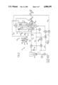
- FIG. 1 is a schematic diagram of a first embodiment of a powder feeding system according to the present invention.
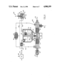
- FIG. 2 is an elevation in cross-section of certain components of the system of FIG. 1.
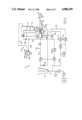
- FIG. 3 is a schematic diagram of a second embodiment of a powder feeding system according to the present invention.
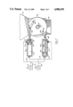
- FIG. 4 is an elevation in cross-section of certain components of the system of FIG. 3.
- FIG. 5 is a schematic diagram of a third embodiment of a powder feeding system according to the present invention.
- FIG. 6 is an elevation in cross-section of certain components of the system in FIG. 5.
- FIG. 7 is a cross-section taken at 7--7 of FIG. 6.
- a powder feeding system 10 includes an enclosed hopper 12 containing a powder 14 up to a normal maximum level 16.
- a carrier conduit 18 for conveying the powder in a carrier gas stream comprises an input conduit 20 receptive of a carrier gas supply 22 and extending to an entrainment location 24 in the bottom of the hopper.
- the carrier conduit further comprises an output conduit 26 extending from the entrainment location to a powder utilization device such as a high pressure type of high velocity thermal spray gun 28.
- Carrier gas supply 22 conventionally comprises a source 30 of compressed air, nitrogen, argon or the like as required for end point utilization, a first solenoid valve S1, a high pressure regulator R1, a pressure gauge G1, gas line 31 and a gas flow meter 32.
- a pinch valve (not shown) may be inserted in conduit 26 near gun 28 to prevent backflow of combustible gases from the gun when the carrier flow is off.
- Entrainment of powder into carrier conduit 18 at entrainment location 24 is effected through at least one intake orifice 34 in the conduit, for example a 1.02 mm orifice in a 1.07 mm inside diameter carrier conduit. Entrainment occurs with the discharging of a feed gas into hopper 12 at a regulated pressure such as to cause entrainment of the powder into the carrier gas stream through orifice 34 at a feed rate responsive to the regulated pressure.
- a feed regulator such as a differential pressure regulator R2 is receptive of pressurized gas tapped from supply line 31.
- the regulator has a reference pressure inlet 36 in gas pressure communication with the carrier conduit by way of a gas bleeder line 38 which detects carrier gas pressure.
- a feed gas line 40 connects the output of the regulator to hopper 12 with a second gas shutoff valve such as a solenoid valve S2 disposed in the feed gas line.
- the feed gas line leads to the upper part of the hopper 42 above the maximum powder level 16.
- the feed gas simply is allowed to diffuse through the powder to a locally fluidized powder zone adjacent the intake orifice.
- the entrainment system means also comprises a vertical tube 44 mounted on a support plug 46 and held with a retaining spring 48 under a hopper cover 50 (removably sealed to the hopper in the usual manner) such that tube 44 extends from above maximum powder level 16 in the hopper to a point proximate the powder entrainment location 24.
- a screen 52 for example a 40 micron screen, is mounted on the bottom of tube 44 to diffuse gas into the powder from the tube.
- the tube further has an intake port 54 therein above the maximum powder level receptive of feed gas from the hopper.
- a rubber or other elastomer duckbill valve 56 or the like is disposed in a valve body 58 at intake port 54 to prevent gas from flowing back into the tube so as to clog screen 52.
- a further blocking screen 60 prevents powder from backing into the feed gas line.
- a large mesh screen 62 such as 20 mesh (841 microns) capable of passing all of the desired powder except lumps and other large contaminants is disposed near the lower part of the hopper and also functions to help disperse powder into the bottom.
- a conventional air or electrically driven vibrator 64 is mounted under the bottom of the hopper.
- Differential regulator R2 (FIG. 1), is of the conventional type, such as Model 11-118 sold by Norgren, modified for differential pressure regulation, or as shown in aforementioned U.S. Pat. No. 4,747,731.
- Regulator R2 follows the carrier gas pressure via line 38 for effecting the regulated pressure or line 40.
- the regulator is adjustable so as to provide the regulated pressure equal to the carrier gas pressure increased by a selected feed pressure increment. This arrangement effects a feed pressure operating at the pressure increment above the carrier pressure regardless of the backpressure from the thermal spray gun or other utilization.
- gas bleeder line 38 has a constricted flow input 66 and an outlet connection 68 to output conduit 26 such as to provide a continuous bleeding of gas through the bleeder line.
- Line pressure is taken at pressure points 70 in the gas bleeder line, and the line pressure is representative of the carrier gas pressure in the output conduit.
- a bleed supply 72 from input conduit 20 provides a bleed gas supply at a bleed supply pressure equal to the carrier gas pressure in the input conduit increased by a selected bleed pressure increment.
- the bleed supply preferably comprises a regulated relief valve R3 such as Model VO6 sold by Norgren and modified for differential pressure regulation, which is disposed in an input line between carrier gas supply 22 and input conduit 20 such as to provide the bleed supply pressure at a tap location 74 in an input line 76 connecting carrier supply 22 to relief valve R3.
- the constricted flow input is connected to the tap location.
- Constrictor 66 for example, consists of a 3 cm long tube with a 0.15 mm inside diameter.
- a powder blocker such as an elastomer duckbill check valve 78 should be placed in input conduit 20 to prevent powder from backing up into regulator R3.
- Outlet connection 68 comprises a merger fitting 80 (FIG. 2) having a first conduit 82 therein constituting a portion of output conduit 26.
- a second conduit 84 therein has a first end receptive of the bleed gas from bleeder line 38 and a second end 88 merged into first conduit 82 at an acute angle A with respect to the direction of carrier gas flow in first conduit 82.
- the acute angle is, e.g., about 30° to minimize entry of powder into bleeder line 38.
- Further powder blocking means such an elastomer duckbill valve 90 should also be placed in the bleeder line near outlet connection 68.
- a differential pressure gauge G2 (FIG. 1) is connected between feed gas line 40 and bleeder line 38. This pressure gauge is responsive of hopper pressure and the line pressure for providing a measure of powder feed rate.
- Valve means 92 is associated with entrainment location 24, having an open position for allowing powder entrainment into the carrier conduit from the hopper and a closed position for preventing the powder entrainment.
- the valve means comprises a first carrier gas shutoff valve P1 disposed in input conduit 20, preferably proximate the entrainment location, and a second carrier gas shutoff valve P2 disposed in the output conduit, also preferably proximate the entrainment location.
- a carrier bypass conduit 94 is connected between a fitting 95 on input conduit 20 and the output conduit so as to bypass hopper 12 and shutoff valves P1, P2.
- a bypass shutoff valve P3 is disposed in the bypass conduit.
- each of the shutoff valves P1,P2,P3 comprises an elastomer pinch valve operated by valve gas pressure from a respective valve pressure source.
- Each pinch valve (detailed for P3 in FIG. 2) is an elastomer tube 96 connected within a stabilizing screen 97 in its respective gas line and enclosed in a jacket 98 receptive of valve pressure via a port 100 Upon application of valve pressure to the jacket the valve is pinched into a shutoff position.
- Valve controls 102 selectively open and close shutoff valves P1,P2,P3 such that the first and second carrier gas shutoff valves P1,P2 are opened and closed jointly, and bypass shutoff valve P3 is open when carrier gas shutoff valves P1,P2 are closed and bypass shutoff valve P3 is closed when carrier gas shutoff valves P1,P2 are open.
- the valve pressure source includes a valve pressure regulator preferably comprising a differential pressure regulator R4, similar to regulator R2, receptive of supply gas on a gas line 104 tapped from carrier gas supply line 31.
- Regulator R4 has a pressure inlet 105 connected from gas bleeder line 38 so as to be responsive to the carrier gas pressure.
- the regulator is set to provide the valve pressure at a level that is equal to the carrier gas pressure increased by a selected valve pressure increment sufficient to operate the shutoff valves, i.e. pinch the elastomer tubes, regardless of the pressure in the carrier conduit or the bypass.
- a first solenoid valve S3 is disposed in a gas line 106 connected between differential regulator R4 and a divided line 108 to each of the first and second pinch valves P1,P2.
- a second solenoid S4 is disposed in another gas line 110 from regulator R4 to bypass pinch valve P3.
- Solenoid valves S3,S4 are of the type with relief ports 112 that exhaust their respective outputs to atmosphere when closing off pressure to respective lines 108,110 from the differential regulator.
- Control signals on electrical conductors 114 from a control console 116 or computer or the like operate all solenoids selectively to apply the valve gas pressure to the shutoff valves.
- Hopper pressure means are provided for pressurizing the hopper before feeding powder and exhausting the hopper after feeding powder.
- the hopper pressure means comprises a hopper pressurization line 118 which is connected between output conduit 26 and hopper 12 above maximum powder level 16 therein.
- the connection to the output conduit is via a second merger duct 120 also at an acute angle at merger fitting 80.
- a pressurization shutoff valve P4 such as a further pinch valve is disposed in pressurization line 118.
- the valve is pressure actuated by a branch line 122 from line 110 to the bypass shutoff valve P3.
- the valve controls further selectively open the pressurization shutoff valve when the bypass shutoff valve is open and closes the pressurization shutoff valve when the bypass shutoff valve is closed.
- the hopper pressurization line and valve are replaced by an exhaust system 124 for exhausting gas from the hopper when powder feeding is terminated.
- a check valve 126 such as an elastomer duckbill is disposed in feed gas line 140 for preventing or at least impeding gas and powder flow from the hopper from backing through the feed gas line.
- Solenoid shutoff valve S2 relieves pressure from the feed gas line to atmosphere through relief port 128 when valve S2 is closed, as described above for valves S3 and S4.
- a differential exhaust valve 130 is responsive of feed gas pressure in feed gas line 40 taken from a pressure tap 132 located between check valve 126 and shutoff valve S2, such as to exhaust gas from the hopper whenever the hopper pressure exceeds the feed gas pressure. Otherwise the components are essentially the same as in FIGS. 1 and 2, and numeral designations are duplicated.
- the differential exhaust valve comprises a hollow body 134 and a flexible diaphragm 136 mounted in the body to separate a first cavity 138 and a second cavity 140 therein.
- a rigid disk 142 somewhat smaller than diaphragm 136 and secured thereto with adhesive provides some support while allowing the flexibility.
- An open tubular member 144 extends into body 134 through first cavity 138 to a point 146 adjacent the diaphragm such as to normally be sealed thereby.
- a gas connecting line 148 is connected between second cavity 140 and pressure tap 132.
- An exhaust conduit 150 is connected between hopper 12 and first cavity 138.
- the system otherwise is the same as described for FIGS. 1 and 2 and the same component numeral designations are applicable. If the feeding system is operated at below atmosphere pressures, a vacuum pump or the like may be connected to all exhausting lines such as lines 128, 144.
- a pressure in first cavity 138 greater than a pressure in second cavity 140 moves diaphragm 136 away from tubular member 144 to allow gas to exhaust from the hopper through the first cavity.
- a pressure in the first cavity substantially equal to or less than the pressure in the second cavity closes the diaphragm against the tube, preventing the first cavity from exhausting the hopper.
- valve means comprises closure means for selectively closing off the carrier conduit at the entrainment location from entraining powder from the hopper .
- first and second carrier gas shutoff valves are omitted and replaced by closure means for closing off orifice 34 from the hopper.
- the bypass conduit, the hopper pressurization line and associated valves of FIGS. 1-4 are omitted.
- An ordinary pressure regulator R5 replaces differential regulator R4. The system otherwise is the same as described for FIGS. 3 and 4 and has the same component numeral designations applicable.
- Carrier conduit 18 has powder entrainment orifice 34 therein receptive of powder at the powder entrainment location.
- a closure means 151 comprises a sleeve 152 disposed on carrier conduit 18 at the powder entrainment location.
- the tight fitting sleeve is rotatable on the powder conduit, the sleeve being made, for example, of PTFE plastic.
- the sleeve has an opening 154 therein alignable with the entrainment orifice 34 in an open position (shown) and rotatable to a non-aligned closed position 158 with the sleeve covering the orifice.
- a sleeve extension assembly 160 extends through hopper 12 with one or two 0-ring seals 171 (one shown).
- a flange 162 on extension 160 has diametrically placed pivot pins 163.
- a pair of cylinders 164,165 mounted on a block 166 have pistons 167 therein with connecting rods 168 with knee joints 169 to the respective pivot pins 163.
- the pistons have further 0-ring seals 170 separating an inner chamber 161 and an outer chamber 172 in each cylinder.
- a first gas line 173 is made with a "T" connection to a line 167 from solenoid valve S3, and provide gas to inner chamber 161 of first cylinder 164 and outer chamber 172 of second cylinder 165.
- a second gas line connection 174 is similarly made from a line 178 and valve S4 to the outer chamber 172 of first cylinder 164 and the inner chamber 161 of second cylinder 165.
- Valve gas is selectively applied to chambers 161,172.
- the first and second valve gas pressures are applied alternatively to the respective first and second chambers so as to selectively rotate the sleeve between the open position (shown) and the closed position.
- FIGS. 5 and 6 Screen 52 (FIGS. 1-4) at the bottom of vertical tube 44 may be replaced (in FIGS. 5 and 6) by a duckbill valve 182 to keep powder out of the tube and there is no duckbill at intake port 54.
- carrier gas passes from source 30 at, e.g. 12.3 kg/cm 2 (175 psig), through open solenoid valve S1 into regulator R1 which is set for 8.75 kg/cm 2 (125 psig) output.
- Flowmeter 32 throttles the carrier flow at a desired rate such as 9.4 1/min (20 scfh) and maintains carrier flow through any normal range of backpressures from gun 28 such as up to 7 kg/cm 2 (100 psig).
- Relief valve R3 is set to provide (e.g.) a 2.1 kg/cm 2 (30 psi) backpressure above the carrier pressure in input conduit 20.
- the 2.1 kg/cm 2 ensures positive flow through restrictor 66 which feeds gas through the gas bleeder line 38.
- Feed regulator R3 is preset for, (e.g.) a 0.2 kg/cm 2 (3 psi) pressure increment according to the desired powder feed rate.
- the backpressure in bleeder line 38 also pilots regulator R4 to 3.7 kg/cm 2 (53 psig) although there is no feed gas flow through closed solenoid valve S3 yet. Once pressure in the hopper reaches the backpressure, carrier gas again flows through the output conduit.
- solenoid valve S3 In the feed mode solenoid valve S3 is closed and solenoid valves S3,S4 are opened, so that carrier shutoff valves P1,P2 open and bypass and pressurization valves P3,P4 close.
- Feed gas flows to hopper 12 and thence through vertical tube 44 and also perhaps partially through the powder 14 in the hopper to the entrain powder through pickup orifice 34.
- the feed gas pressure differential over the backpressure determines feed rate, which may be monitored with gauge G2.
- Regulator R2 may be readjusted to adjust the powder feed rate.
- solenoid valve 53 is opened and solenoid valves S2,S4 are closed, so that carrier shutoff valves P1,P2 close and bypass valve P3 and pressurization valve P4 open. Feed gas flow stops and the incremental hopper pressure is released through line 112 from valve S3 until gun backpressure is equalized. When the gun is turned off hopper gas further equalizes through pressurization line 118, output conduit 26 and gun 28.
- FIGS. 3 and 4 operates similarly except that solenoid valve S2 may be opened initially along with supply valve S1 for the ready mode, since no feed gas flow can occur with valves closed.
- solenoid valve S2 may be opened initially along with supply valve S1 for the ready mode, since no feed gas flow can occur with valves closed.
- the various pressures adjust including full pressurization of the hopper at 3.7 kg/cm 2 from feed line 40. Since pressures are balanced in cavities 138,140 of differential exhaust valve 130 the hopper is not exhausted at this stage.
- solenoid valve S3 In the feed mode for FIGS. 3 and 4 solenoid valve S3 is closed and solenoid valve S4 is opened, so that carrier shutoff valves P1,P2 open and bypass valve P4 closes. Powder feed commences essentially instantly because of the preliminary pressurization, which is a particular advantage of this embodiment.
- the valve settings are reversed for stopping feed with the gun still lit. Any excess pressure in the hopper over feed line pressure causes differential valve 130 to open and exhaust the hopper until it equalizes to the feed gas pressure.
- solenoid valve 52 When the feeder is shut down solenoid valve 52 is turned off so that feed line 40 exhausts through the line 128 from valve S2 to atmospheric pressure, allowing the exhaust valve to similarly exhaust the hopper.
- This type of exhaust valve is better than a solenoid operated pinch valve because exhausting will automatically occur whenever the hopper pressure exceeds feed line pressure even during operation, resulting in quick readjustments of feed rate as needed.
- FIGS. 4-7 The embodiment of FIGS. 4-7 is operated the same as that of FIGS. 3 and 4. Solenoids S3,S4 actuate powder closure valve 151 instead of the carrier pinch valves replaced, and no carrier bypass is necessary because carrier gas can flow through the carrier conduit with the closure valve open or closed.
- the exhaust valve operates as for FIG. 2. This embodiment eliminates a slug of powder that may lodge in the entrainment section between pinch valves.
- the present invention provides a powder feeding system for a thermal spray gun or the like that produces a high backpressure into the powder carrier gas conduit.
- the feeding system automatically and quickly adjusts its internal pressures to maintain an accurate powder feed rate.
- the several embodiments have specific advantages as indicated.
- the system is not restricted to backpressures above atmospheric, and may be utilized for applications such as plasma spraying in low pressure chambers.
Priority Applications (7)
| Application Number | Priority Date | Filing Date | Title |
|---|---|---|---|
| US07/260,625 US4900199A (en) | 1988-10-21 | 1988-10-21 | High pressure power feed system |
| CA000611676A CA1324621C (en) | 1988-10-21 | 1989-09-15 | High pressure powder feed system |
| CN89107830A CN1037333C (zh) | 1988-10-21 | 1989-10-09 | 高压送粉系统 |
| JP1270490A JP3061819B2 (ja) | 1988-10-21 | 1989-10-19 | 粉末供給装置 |
| BR898905353A BR8905353A (pt) | 1988-10-21 | 1989-10-20 | Sistema de alimentacao de po |
| EP89119532A EP0365038B1 (de) | 1988-10-21 | 1989-10-20 | Hochdruck-Pulverzuführungssystem |
| DE89119532T DE68908832T2 (de) | 1988-10-21 | 1989-10-20 | Hochdruck-Pulverzuführungssystem. |
Applications Claiming Priority (1)
| Application Number | Priority Date | Filing Date | Title |
|---|---|---|---|
| US07/260,625 US4900199A (en) | 1988-10-21 | 1988-10-21 | High pressure power feed system |
Publications (1)
| Publication Number | Publication Date |
|---|---|
| US4900199A true US4900199A (en) | 1990-02-13 |
Family
ID=22989926
Family Applications (1)
| Application Number | Title | Priority Date | Filing Date |
|---|---|---|---|
| US07/260,625 Expired - Lifetime US4900199A (en) | 1988-10-21 | 1988-10-21 | High pressure power feed system |
Country Status (7)
| Country | Link |
|---|---|
| US (1) | US4900199A (de) |
| EP (1) | EP0365038B1 (de) |
| JP (1) | JP3061819B2 (de) |
| CN (1) | CN1037333C (de) |
| BR (1) | BR8905353A (de) |
| CA (1) | CA1324621C (de) |
| DE (1) | DE68908832T2 (de) |
Cited By (28)
| Publication number | Priority date | Publication date | Assignee | Title |
|---|---|---|---|---|
| US5145293A (en) * | 1990-11-07 | 1992-09-08 | The Perkin-Elmer Corporation | Powder pickup device with extended life |
| US5334235A (en) * | 1993-01-22 | 1994-08-02 | The Perkin-Elmer Corporation | Thermal spray method for coating cylinder bores for internal combustion engines |
| US6106202A (en) * | 1998-05-04 | 2000-08-22 | Nol-Tec Systems, Inc. | Pneumatic conveying air assist line with air bleed |
| US6176647B1 (en) * | 1996-09-24 | 2001-01-23 | Rid Corporation | Instrument for measuring mass flow rate of powder, and electrostatic powder coating apparatus utilizing the same |
| US20050121545A1 (en) * | 2003-12-03 | 2005-06-09 | Avetik Harutyunyan | Dry powder injector |
| US20050252450A1 (en) * | 2002-01-08 | 2005-11-17 | Flame Spray Industries, Inc. | Plasma spray method and apparatus for applying a coating utilizing particle kinetics |
| WO2006084253A2 (en) * | 2005-02-04 | 2006-08-10 | Durr Systems, Inc. | Powder paint transport system and method |
| US20070092380A1 (en) * | 2005-10-07 | 2007-04-26 | Fulkerson Terrence M | Pump with Suction and Pressure Control for Dry Particulate Material |
| US20070212482A1 (en) * | 2006-03-10 | 2007-09-13 | James Nevin | Method of treating particles |
| US20130058728A1 (en) * | 2011-09-02 | 2013-03-07 | Gang Xiong | Feeder system and method for a vapor transport deposition system |
| US20140044578A1 (en) * | 2011-02-14 | 2014-02-13 | Gema Switzerland Gmbh | Powder pump for conveying coating powder |
| US8684284B2 (en) | 2006-11-24 | 2014-04-01 | Honda Motor Co., Ltd. | Injector for large amount of aerosol powder for synthesis of carbon nanotubes |
| US20140251212A1 (en) * | 2013-03-07 | 2014-09-11 | Tokyo Electron Limited | Hopper and thermal spraying apparatus |
| US20140294517A1 (en) * | 2013-04-02 | 2014-10-02 | National Research Council Of Canada | Powder feeder method and system |
| US8973523B2 (en) * | 2008-11-27 | 2015-03-10 | Oerlikon Metco Ag | Device for creating and conveying a gas-powder mixture |
| CN104495390A (zh) * | 2014-12-10 | 2015-04-08 | 大唐彬长发电有限责任公司 | 一种输送泵节流孔电加热保温系统 |
| US20150166269A1 (en) * | 2013-12-17 | 2015-06-18 | Cnh Canada, Ltd. | System for increasing throughput of an agricultural product metering system |
| CN105253628A (zh) * | 2015-08-07 | 2016-01-20 | 上海空间推进研究所 | 气垫运输设备的气路控制系统 |
| US20160122138A1 (en) * | 2013-04-03 | 2016-05-05 | Gema Switzerland Gmbh | Powder conveyor and associated operating method |
| CN106672632A (zh) * | 2015-11-09 | 2017-05-17 | 中联重科股份有限公司 | 用于气力输送装置的控制方法、设备、系统及工程机械 |
| WO2017099758A1 (en) * | 2015-12-09 | 2017-06-15 | Oerlikon Metco (Us) Inc. | Powder hopper for difficult-to-flow powders for use in thermal spraying and method making and using the same |
| USD817555S1 (en) | 2015-12-09 | 2018-05-08 | Oerlikon Metco (Us) Inc. | Hopper |
| WO2018222385A1 (en) | 2017-05-31 | 2018-12-06 | Oerlikon Metco (Us) Inc. | Powder feed control system and method |
| US20190111445A1 (en) * | 2016-04-29 | 2019-04-18 | Wagner International Ag | Powder conveyor for conveying coating powder to a powder applicator, powder coating system, and method for operating the powder conveyor |
| US20200024085A1 (en) * | 2016-04-25 | 2020-01-23 | Chevron Phillips Chemical Company Lp | Measurement of Product Pellets Flow Rate |
| US10562051B2 (en) | 2015-12-09 | 2020-02-18 | Oerlikon Metco (Us) Inc. | Powder hopper for difficult-to-flow powders for use in thermal spraying and method making and using the same |
| US20220016653A1 (en) * | 2018-12-31 | 2022-01-20 | Gema Switzerland Gmbh | Dilute phase powder pump and method for operating a dilute phase powder pump |
| US11344902B2 (en) * | 2019-01-25 | 2022-05-31 | Wagner International Ag | Powder conveying device for coating powder and powder coating system comprising a powder conveying device |
Families Citing this family (11)
| Publication number | Priority date | Publication date | Assignee | Title |
|---|---|---|---|---|
| US5752788A (en) * | 1994-11-30 | 1998-05-19 | Nordson Corporation | System and method of pumping a constant volume of powder |
| GB9509170D0 (en) * | 1995-05-05 | 1995-06-28 | Briggs Andrew I | Particulate dispenser |
| DE19613967A1 (de) * | 1996-04-09 | 1997-10-16 | Gema Volstatic Ag | Vorrichtung zur Sprühbeschichtung |
| DE102004014058A1 (de) * | 2004-03-23 | 2005-10-13 | Bayer Ag | Vorrichtung und Verfahren zur pneumatischen Förderung von feinteiligen Schüttgütern |
| DE102006057898B4 (de) * | 2006-12-08 | 2011-06-01 | Eisenmann Anlagenbau Gmbh & Co. Kg | Vorrichtung zum Fördern fluidisierbarer Medien |
| US8887649B2 (en) * | 2011-02-10 | 2014-11-18 | General Electric Company | System to vent solid feed pump |
| RU2598429C2 (ru) * | 2011-04-29 | 2016-09-27 | Берри Метал Кампани, Сша | Способ и система доставки газа и зернистого материала для металлургического агрегата |
| CN102328091B (zh) * | 2011-06-11 | 2013-06-26 | 山东理工大学 | 气雾化快凝磁性磨料制备送混粉器及送混粉控制方法 |
| CN102698654B (zh) * | 2012-05-08 | 2014-03-05 | 北京航天动力研究所 | 一种给配料系统 |
| EP3406547B1 (de) * | 2017-05-23 | 2020-08-05 | Piab Ab | Filterüberwachung in pneumatischen transportsystemen |
| DE102018113643A1 (de) * | 2018-06-07 | 2019-12-12 | Durum Verschleißschutz GmbH | Vorrichtung zur Beschichtung einer Oberfläche |
Citations (17)
| Publication number | Priority date | Publication date | Assignee | Title |
|---|---|---|---|---|
| US2623793A (en) * | 1949-12-24 | 1952-12-30 | Dow Chemical Co | Pneumatic conveyer and feeder for loose solids |
| US3291536A (en) * | 1964-09-21 | 1966-12-13 | David K Smoot | Powdered material conveyor system |
| US3365242A (en) * | 1965-12-14 | 1968-01-23 | Siderurgie Fse Inst Rech | Apparatus for discharging a gas from a container at a constant rate through several conduits |
| US3432208A (en) * | 1967-11-07 | 1969-03-11 | Us Air Force | Fluidized particle dispenser |
| US3501097A (en) * | 1966-12-29 | 1970-03-17 | Metco Inc | Powder feed device for flame spray guns |
| US3976332A (en) * | 1969-05-26 | 1976-08-24 | Metco, Inc. | Powder feed device for flame spray guns |
| US4284032A (en) * | 1978-11-14 | 1981-08-18 | Gema Ag | Pneumatic conveyor of adjustable conveyance capacity for powdered to granular bulk material |
| US4381898A (en) * | 1981-01-21 | 1983-05-03 | Eutectic Corporation | Device for the controlled feeding of powder material |
| US4561808A (en) * | 1984-06-04 | 1985-12-31 | Metco Inc. | Powder feed pickup device for thermal spray guns |
| US4582254A (en) * | 1984-06-06 | 1986-04-15 | Eutectic Corporation | Device for the controlled multiple feeding of powder material |
| US4613259A (en) * | 1984-11-28 | 1986-09-23 | United Technologies Corporation | Apparatus for controlling powder flow rate in a carrier gas |
| US4740112A (en) * | 1982-08-27 | 1988-04-26 | Electro-Plasma, Inc. | Powder feed control system |
| US4743143A (en) * | 1985-09-17 | 1988-05-10 | Hideo Nagasaka | Powder flow-rate measuring and controlling apparatus |
| US4747731A (en) * | 1986-03-25 | 1988-05-31 | Hideo Nagasaka | Automatic powder feeding apparatus |
| US4758117A (en) * | 1984-12-28 | 1988-07-19 | Kawasaki Steel Corp. | Method for the transportation of a particulate material at controlled rate |
| JPH06312524A (ja) * | 1993-04-30 | 1994-11-08 | Sharp Corp | サーマルヘッドを用いる印字装置 |
| JPH107316A (ja) * | 1996-06-20 | 1998-01-13 | Somar Corp | フィルム剥離方法及び装置 |
Family Cites Families (1)
| Publication number | Priority date | Publication date | Assignee | Title |
|---|---|---|---|---|
| LU41375A1 (de) * | 1962-03-13 | 1962-05-17 |
-
1988
- 1988-10-21 US US07/260,625 patent/US4900199A/en not_active Expired - Lifetime
-
1989
- 1989-09-15 CA CA000611676A patent/CA1324621C/en not_active Expired - Lifetime
- 1989-10-09 CN CN89107830A patent/CN1037333C/zh not_active Expired - Fee Related
- 1989-10-19 JP JP1270490A patent/JP3061819B2/ja not_active Expired - Lifetime
- 1989-10-20 DE DE89119532T patent/DE68908832T2/de not_active Expired - Lifetime
- 1989-10-20 BR BR898905353A patent/BR8905353A/pt not_active IP Right Cessation
- 1989-10-20 EP EP89119532A patent/EP0365038B1/de not_active Expired - Lifetime
Patent Citations (18)
| Publication number | Priority date | Publication date | Assignee | Title |
|---|---|---|---|---|
| US2623793A (en) * | 1949-12-24 | 1952-12-30 | Dow Chemical Co | Pneumatic conveyer and feeder for loose solids |
| US3291536A (en) * | 1964-09-21 | 1966-12-13 | David K Smoot | Powdered material conveyor system |
| US3365242A (en) * | 1965-12-14 | 1968-01-23 | Siderurgie Fse Inst Rech | Apparatus for discharging a gas from a container at a constant rate through several conduits |
| US3501097A (en) * | 1966-12-29 | 1970-03-17 | Metco Inc | Powder feed device for flame spray guns |
| US3432208A (en) * | 1967-11-07 | 1969-03-11 | Us Air Force | Fluidized particle dispenser |
| US3976332B1 (de) * | 1969-05-26 | 1986-04-22 | ||
| US3976332A (en) * | 1969-05-26 | 1976-08-24 | Metco, Inc. | Powder feed device for flame spray guns |
| US4284032A (en) * | 1978-11-14 | 1981-08-18 | Gema Ag | Pneumatic conveyor of adjustable conveyance capacity for powdered to granular bulk material |
| US4381898A (en) * | 1981-01-21 | 1983-05-03 | Eutectic Corporation | Device for the controlled feeding of powder material |
| US4740112A (en) * | 1982-08-27 | 1988-04-26 | Electro-Plasma, Inc. | Powder feed control system |
| US4561808A (en) * | 1984-06-04 | 1985-12-31 | Metco Inc. | Powder feed pickup device for thermal spray guns |
| US4582254A (en) * | 1984-06-06 | 1986-04-15 | Eutectic Corporation | Device for the controlled multiple feeding of powder material |
| US4613259A (en) * | 1984-11-28 | 1986-09-23 | United Technologies Corporation | Apparatus for controlling powder flow rate in a carrier gas |
| US4758117A (en) * | 1984-12-28 | 1988-07-19 | Kawasaki Steel Corp. | Method for the transportation of a particulate material at controlled rate |
| US4743143A (en) * | 1985-09-17 | 1988-05-10 | Hideo Nagasaka | Powder flow-rate measuring and controlling apparatus |
| US4747731A (en) * | 1986-03-25 | 1988-05-31 | Hideo Nagasaka | Automatic powder feeding apparatus |
| JPH06312524A (ja) * | 1993-04-30 | 1994-11-08 | Sharp Corp | サーマルヘッドを用いる印字装置 |
| JPH107316A (ja) * | 1996-06-20 | 1998-01-13 | Somar Corp | フィルム剥離方法及び装置 |
Cited By (48)
| Publication number | Priority date | Publication date | Assignee | Title |
|---|---|---|---|---|
| US5145293A (en) * | 1990-11-07 | 1992-09-08 | The Perkin-Elmer Corporation | Powder pickup device with extended life |
| US5334235A (en) * | 1993-01-22 | 1994-08-02 | The Perkin-Elmer Corporation | Thermal spray method for coating cylinder bores for internal combustion engines |
| US6176647B1 (en) * | 1996-09-24 | 2001-01-23 | Rid Corporation | Instrument for measuring mass flow rate of powder, and electrostatic powder coating apparatus utilizing the same |
| US6106202A (en) * | 1998-05-04 | 2000-08-22 | Nol-Tec Systems, Inc. | Pneumatic conveying air assist line with air bleed |
| US20050252450A1 (en) * | 2002-01-08 | 2005-11-17 | Flame Spray Industries, Inc. | Plasma spray method and apparatus for applying a coating utilizing particle kinetics |
| US8550752B2 (en) * | 2003-12-03 | 2013-10-08 | Honda Motor Co., Ltd. | Dry powder injector |
| US20050121545A1 (en) * | 2003-12-03 | 2005-06-09 | Avetik Harutyunyan | Dry powder injector |
| US7134618B2 (en) * | 2003-12-03 | 2006-11-14 | Honda Motor Co., Ltd | Dry powder injector |
| US20070057097A1 (en) * | 2003-12-03 | 2007-03-15 | Avetik Harutyunyan | Dry Powder Injector |
| WO2006084253A2 (en) * | 2005-02-04 | 2006-08-10 | Durr Systems, Inc. | Powder paint transport system and method |
| WO2006084253A3 (en) * | 2005-02-04 | 2006-09-21 | Durr Systems Inc | Powder paint transport system and method |
| US8167517B2 (en) | 2005-10-07 | 2012-05-01 | Nordson Corporation | Pump with suction and pressure control for dry particulate material |
| US20070092380A1 (en) * | 2005-10-07 | 2007-04-26 | Fulkerson Terrence M | Pump with Suction and Pressure Control for Dry Particulate Material |
| US20100221125A1 (en) * | 2005-10-07 | 2010-09-02 | Nordson Corporation | Pump with suction and pressure control for dry particulate material |
| US7731456B2 (en) * | 2005-10-07 | 2010-06-08 | Nordson Corporation | Dense phase pump with open loop control |
| US8491227B2 (en) | 2005-10-07 | 2013-07-23 | Nordson Corporation | Pump for powder coating materials with data structure for storing powder flow recipes |
| US20070212482A1 (en) * | 2006-03-10 | 2007-09-13 | James Nevin | Method of treating particles |
| US8684284B2 (en) | 2006-11-24 | 2014-04-01 | Honda Motor Co., Ltd. | Injector for large amount of aerosol powder for synthesis of carbon nanotubes |
| US8973523B2 (en) * | 2008-11-27 | 2015-03-10 | Oerlikon Metco Ag | Device for creating and conveying a gas-powder mixture |
| US20140044578A1 (en) * | 2011-02-14 | 2014-02-13 | Gema Switzerland Gmbh | Powder pump for conveying coating powder |
| US20130058728A1 (en) * | 2011-09-02 | 2013-03-07 | Gang Xiong | Feeder system and method for a vapor transport deposition system |
| US9359668B2 (en) * | 2011-09-02 | 2016-06-07 | First Solar, Inc. | Feeder system and method for a vapor transport deposition system |
| TWI615205B (zh) * | 2013-03-07 | 2018-02-21 | 東京威力科創股份有限公司 | 儲料槽及熔噴裝置 |
| US20140251212A1 (en) * | 2013-03-07 | 2014-09-11 | Tokyo Electron Limited | Hopper and thermal spraying apparatus |
| KR20140110758A (ko) * | 2013-03-07 | 2014-09-17 | 도쿄엘렉트론가부시키가이샤 | 호퍼 및 용사 장치 |
| US20140294517A1 (en) * | 2013-04-02 | 2014-10-02 | National Research Council Of Canada | Powder feeder method and system |
| US9505566B2 (en) * | 2013-04-02 | 2016-11-29 | National Research Council Of Canada | Powder feeder method and system |
| US20160122138A1 (en) * | 2013-04-03 | 2016-05-05 | Gema Switzerland Gmbh | Powder conveyor and associated operating method |
| US9745148B2 (en) * | 2013-04-03 | 2017-08-29 | Gema Switzerland Gmbh | Powder conveyor and associated operating method |
| US20150166269A1 (en) * | 2013-12-17 | 2015-06-18 | Cnh Canada, Ltd. | System for increasing throughput of an agricultural product metering system |
| US9546051B2 (en) * | 2013-12-17 | 2017-01-17 | Cnh Industrial Canada, Ltd. | System for increasing throughput of an agricultural product metering system |
| CN104495390A (zh) * | 2014-12-10 | 2015-04-08 | 大唐彬长发电有限责任公司 | 一种输送泵节流孔电加热保温系统 |
| CN105253628A (zh) * | 2015-08-07 | 2016-01-20 | 上海空间推进研究所 | 气垫运输设备的气路控制系统 |
| CN106672632A (zh) * | 2015-11-09 | 2017-05-17 | 中联重科股份有限公司 | 用于气力输送装置的控制方法、设备、系统及工程机械 |
| CN106672632B (zh) * | 2015-11-09 | 2019-03-15 | 中联重科股份有限公司 | 用于气力输送装置的控制方法、设备、系统及工程机械 |
| USD817555S1 (en) | 2015-12-09 | 2018-05-08 | Oerlikon Metco (Us) Inc. | Hopper |
| WO2017099758A1 (en) * | 2015-12-09 | 2017-06-15 | Oerlikon Metco (Us) Inc. | Powder hopper for difficult-to-flow powders for use in thermal spraying and method making and using the same |
| US10562051B2 (en) | 2015-12-09 | 2020-02-18 | Oerlikon Metco (Us) Inc. | Powder hopper for difficult-to-flow powders for use in thermal spraying and method making and using the same |
| USD885684S1 (en) | 2015-12-09 | 2020-05-26 | Oerlikon Metco (Us) Inc. | Hopper |
| US11673750B2 (en) * | 2016-04-25 | 2023-06-13 | Chevron Phillips Chemical Company Lp | Measurement of product pellets flow rate |
| US20200024085A1 (en) * | 2016-04-25 | 2020-01-23 | Chevron Phillips Chemical Company Lp | Measurement of Product Pellets Flow Rate |
| US10717096B2 (en) * | 2016-04-29 | 2020-07-21 | Wagner International Ag | Powder conveyor for conveying coating powder to a powder applicator, powder coating system, and method for operating the powder conveyor |
| US20190111445A1 (en) * | 2016-04-29 | 2019-04-18 | Wagner International Ag | Powder conveyor for conveying coating powder to a powder applicator, powder coating system, and method for operating the powder conveyor |
| WO2018222385A1 (en) | 2017-05-31 | 2018-12-06 | Oerlikon Metco (Us) Inc. | Powder feed control system and method |
| US10401246B2 (en) | 2017-05-31 | 2019-09-03 | Oerlikon Metco (Us) Inc. | Powder feed control system and method |
| US20220016653A1 (en) * | 2018-12-31 | 2022-01-20 | Gema Switzerland Gmbh | Dilute phase powder pump and method for operating a dilute phase powder pump |
| US11931762B2 (en) * | 2018-12-31 | 2024-03-19 | Gema Switzerland Gmbh | Dilute phase powder pump and method for operating a dilute phase powder pump |
| US11344902B2 (en) * | 2019-01-25 | 2022-05-31 | Wagner International Ag | Powder conveying device for coating powder and powder coating system comprising a powder conveying device |
Also Published As
| Publication number | Publication date |
|---|---|
| CN1037333C (zh) | 1998-02-11 |
| JP3061819B2 (ja) | 2000-07-10 |
| DE68908832T2 (de) | 1993-12-23 |
| EP0365038B1 (de) | 1993-09-01 |
| EP0365038A2 (de) | 1990-04-25 |
| JPH02158522A (ja) | 1990-06-19 |
| BR8905353A (pt) | 1990-05-22 |
| DE68908832D1 (de) | 1993-10-07 |
| CN1041923A (zh) | 1990-05-09 |
| EP0365038A3 (en) | 1990-11-28 |
| CA1324621C (en) | 1993-11-23 |
Similar Documents
| Publication | Publication Date | Title |
|---|---|---|
| US4900199A (en) | High pressure power feed system | |
| US5615980A (en) | Injector-feed device for pneumatic feed of powder | |
| US4502819A (en) | Constant discharge device in a conveyor for powdery and granular materials | |
| US3976332A (en) | Powder feed device for flame spray guns | |
| JP2002517702A (ja) | ガスバーナーの調整装置 | |
| EP0166930B1 (de) | Puderspeisevorrichtung für Flammenspritzpistole | |
| JPH0686950A (ja) | 粉末射出装置 | |
| US5312016A (en) | Mastic applicator system | |
| GB1021645A (en) | Improvements relating to a method for controlling the flow of solid pulverulent substances in suspension in a gas | |
| JP2002523216A (ja) | 粉末スプレイ・コーティング装置 | |
| US5269463A (en) | Fluidized powder feed system with pressurized hopper | |
| ATE187903T1 (de) | Pulver-sprühbeschichtungsvorrichtung | |
| US3501097A (en) | Powder feed device for flame spray guns | |
| US5906858A (en) | Method and apparatus for conveying a pulverulent material by means of an injector | |
| US4313699A (en) | Quick mount high pressure booster valves | |
| US5722801A (en) | Material conveying system with flow rate control | |
| US5230470A (en) | Flame spray applicator system | |
| US5327755A (en) | Constant flow control for a pressure pot shot peening machine | |
| JP2002273282A (ja) | コーティング粉体のための粉体吹付け装置 | |
| EP0484827B1 (de) | Pulveraufnahmevorrichtung mit langer Lebensdauer | |
| US5193531A (en) | Process and apparatus for controlling a gas pressure and system for supplying gas comprising such device | |
| US6474398B1 (en) | Apparatus for introducing granular mold flux onto the top of a slab being cast within a continuous casting mold | |
| JPH07187387A (ja) | 流量制御装置を有する塗料自動供給装置 | |
| JPS58164692A (ja) | ロツクホツパによる石炭安定供給法 | |
| EP0269900B1 (de) | Luftregler für Atemschutzgerät |
Legal Events
| Date | Code | Title | Description |
|---|---|---|---|
| AS | Assignment |
Owner name: PERKIN-ELMER CORPORATION, THE, 761 MAIN AVE., NORW Free format text: ASSIGNMENT OF ASSIGNORS INTEREST.;ASSIGNORS:SPAULDING, MARK F.;GOEHRING, RICHARD A.;REEL/FRAME:004995/0213 Effective date: 19881020 |
|
| STCF | Information on status: patent grant |
Free format text: PATENTED CASE |
|
| CC | Certificate of correction | ||
| FEPP | Fee payment procedure |
Free format text: PAYOR NUMBER ASSIGNED (ORIGINAL EVENT CODE: ASPN); ENTITY STATUS OF PATENT OWNER: LARGE ENTITY |
|
| FPAY | Fee payment |
Year of fee payment: 4 |
|
| AS | Assignment |
Owner name: SULZER METCO (US), INC., NEW YORK Free format text: MERGER;ASSIGNOR:PERKIN-ELMER CORPORATION, THE;REEL/FRAME:008126/0066 Effective date: 19960702 |
|
| FPAY | Fee payment |
Year of fee payment: 8 |
|
| FPAY | Fee payment |
Year of fee payment: 12 |