US4900167A - Matrix pin printer with adjustable print pin guide - Google Patents
Matrix pin printer with adjustable print pin guide Download PDFInfo
- Publication number
- US4900167A US4900167A US07/262,889 US26288988A US4900167A US 4900167 A US4900167 A US 4900167A US 26288988 A US26288988 A US 26288988A US 4900167 A US4900167 A US 4900167A
- Authority
- US
- United States
- Prior art keywords
- pin
- pin guide
- magnet
- matrix
- Prior art date
- Legal status (The legal status is an assumption and is not a legal conclusion. Google has not performed a legal analysis and makes no representation as to the accuracy of the status listed.)
- Expired - Fee Related
Links
Images
Classifications
-
- B—PERFORMING OPERATIONS; TRANSPORTING
- B41—PRINTING; LINING MACHINES; TYPEWRITERS; STAMPS
- B41J—TYPEWRITERS; SELECTIVE PRINTING MECHANISMS, i.e. MECHANISMS PRINTING OTHERWISE THAN FROM A FORME; CORRECTION OF TYPOGRAPHICAL ERRORS
- B41J25/00—Actions or mechanisms not otherwise provided for
- B41J25/001—Mechanisms for bodily moving print heads or carriages parallel to the paper surface
-
- B—PERFORMING OPERATIONS; TRANSPORTING
- B41—PRINTING; LINING MACHINES; TYPEWRITERS; STAMPS
- B41J—TYPEWRITERS; SELECTIVE PRINTING MECHANISMS, i.e. MECHANISMS PRINTING OTHERWISE THAN FROM A FORME; CORRECTION OF TYPOGRAPHICAL ERRORS
- B41J2/00—Typewriters or selective printing mechanisms characterised by the printing or marking process for which they are designed
- B41J2/22—Typewriters or selective printing mechanisms characterised by the printing or marking process for which they are designed characterised by selective application of impact or pressure on a printing material or impression-transfer material
- B41J2/23—Typewriters or selective printing mechanisms characterised by the printing or marking process for which they are designed characterised by selective application of impact or pressure on a printing material or impression-transfer material using print wires
- B41J2/235—Print head assemblies
- B41J2/25—Print wires
- B41J2/255—Arrangement of the print ends of the wires
-
- B—PERFORMING OPERATIONS; TRANSPORTING
- B41—PRINTING; LINING MACHINES; TYPEWRITERS; STAMPS
- B41J—TYPEWRITERS; SELECTIVE PRINTING MECHANISMS, i.e. MECHANISMS PRINTING OTHERWISE THAN FROM A FORME; CORRECTION OF TYPOGRAPHICAL ERRORS
- B41J2/00—Typewriters or selective printing mechanisms characterised by the printing or marking process for which they are designed
- B41J2/22—Typewriters or selective printing mechanisms characterised by the printing or marking process for which they are designed characterised by selective application of impact or pressure on a printing material or impression-transfer material
- B41J2/23—Typewriters or selective printing mechanisms characterised by the printing or marking process for which they are designed characterised by selective application of impact or pressure on a printing material or impression-transfer material using print wires
- B41J2/235—Print head assemblies
- B41J2/265—Guides for print wires
Definitions
- the invention relates to a matrix pin print head with adjustable print pin guide, where a print pin drive device group and a pin print guide device group, disposed toward a print counter support, are provided with a casing guiding the print pins, and where an electric lifting magnet for a magnet core is disposed in the region of the print pin guide device group, where the magnet core, together with a pin guide carrier, forms an adjustable magnetic discontinuity air gap, and where the pin guide carrier is movable back and forth between two fixedly adjustable positions.
- Such matrix pin print heads with adjustable print pin guide serve to generate various stages of letter-quality printing such as, for example, the generating of near-letter-quality printing as well as letter-quality printing.
- the print pin guide is readjusted by less than a pin distance of about 0.3 mm, whereby the pin distance gaps are filled by further print points/dots.
- the adjustment of the print pin guide therefore requires a very high degree of precision between two fixed positions of impact, where the print pins are guided in a pin guide stone, which is produced from a similar material as the bearing stones for small watches.
- the print pin guide and this pin guide stone are disposed at a relatively long lever arm which, in most cases, is tiltably supported around a hinge in the region of the print pin drive device group.
- the motion of the pin guide stone on an arc with the radius equal to the length of the lever arm is in fact disadvantageous, because the chord height of the arc becomes noticeable in a certain adjustment region.
- this disadvantage has been considered as permissible.
- such adjustable print pin guides have worked in thousands of matrix pin print heads.
- a matrix pin print head for disposal opposite to a print counter support and having a center axis comprising a print pin drive device group.
- a print pin guide device group is disposed facing a print counter support, is connected to the print pin drive device group and includes an adjustable print pin guide.
- Print pins are associated with a print direction, where the center axis of the print head is running in the print direction of the print pins.
- a casing guides the print pins.
- a magnet core is disposed in the area of the print pin guide device group and movable in a guide for the magnet core.
- a set screw is coordinated to the magnet core.
- An electric lifting magnet having a coil center axis and coordinated to the set screw for the magnet core, is disposed in the area of the print pin guide device group perpendicular to the center axis of the matrix print head.
- a pin guide carrier is parallel-adjustable.
- the magnet core together with the pin guide carrier forms an adjustable magnetic discontinuity air gap within the electric lifting magnet.
- the pin guide carrier is movable back and forth between two fixedly adjustable positions.
- the magnet core is connected to the pin guide carrier.
- the electric lifting magnet can include a core bushing for guiding the magnet core connected to the pin guide carrier.
- a threaded nut can be disposed at an end of the core bushing located remote relative to the location of the center axis.
- the set screw can be provided in the threaded nut.
- the set screw can form with the magnet core the adjustable magnetic discontinuity air gap within the electric lifting magnet.
- a bent flat spring can be disposed between the pin guide carrier and the electric lifting magnet.
- the electric lifting magnet can be fixed at the casing of the print pin guide device group.
- the pin guide carrier can form a substantially angular device component.
- Said angular device component can include a first arm and a second arm.
- the magnet core can be attached to the first arm and the pin guide stone can be attached to the second arm.
- the angular device component can be attached with the second arm to a pin guide stone.
- the casing of the print pin guide device component can be formed as a guide with two sides and the angular device component is supported between the sides of said guide.
- a bolt can attach the print pin guide device group via a shim to a plate of the print pin drive device group.
- the electric magnet can comprise only a single exciter coil.
- the single exciter coil can have a diameter of less than 12 millimeters.
- the electric lifting magnet can include a frame of an exciter coil.
- a bent flat spring can rest against the frame of the exciter coil for maintaining the pin guide carrier at a relative distance to the frame, which relative distance can correspond to the width of the magnetic discontinuity air gap or, respectively, to a shifting distance of the print pin guide.
- the pin guide carrier can form a substantially angular device component.
- This angular device component can include a first arm and a second arm.
- the magnet core can be attached to the first arm with a rivet connection and the pin guide stone can be attached to the second arm.
- the angular device component can be attached with the second arm to the pin guide stone.
- the casing of the print pin guide device component can be formed as a guide with two sides, wherein the angular device component can be supported between the sides of said guide for allowing the second arm to move up and down by a distance corresponding to the magnetic discontinuity air gap depending on a setting of the set screw.
- the outer diameter of the electric lifting magnet can be from about 0.8 to 1.2 times the diameter of the magnet core.
- the distance of the pin guide stone from a center axis of the lifting magnet can be from about 2 to 4 times the diameter of the magnet core.
- the length of the magnet core can be from about 1 to 1.3 times the diameter of the magnet core.
- a control method for positioning pins of a matrix pin print head for disposal opposite to a print counter support.
- Said print head has a center axis.
- the control method comprises the following steps.
- a print pin guide device group is disposed toward a print counter support.
- the print pin guide device group is connected to a print pin drive device group.
- Said print pin guide device group includes an adjustable print pin guide and print pins associated with a print direction.
- the center axis of the print head is running in the print direction of the print pins.
- the print pins are guided in a casing.
- a magnet core, disposed in the area of the print pin guide device group, is guided in a guide for moving the magnet core.
- a set screw is set at a distance relative to the magnet core.
- An electric lifting magnet has a coil center axis and is coordinated to the set screw for the magnet core and is disposed in the area of the print pin guide device group perpendicular to the center axis of the matrix print head for adjusting a magnetic discontinuity air gap.
- the magnet core together with a parallel adjustable pin guide carrier forms an adjustable magnetic discontinuity air gap within the electric lifting magnet.
- the pin guide carrier is movable back and forth between two fixedly adjustable positions and the magnet core is connected to the pin guide carrier.
- a position of the magnet core can be maintained with a bent flat spring disposed between the pin guide carrier and the electric lifting magnet.
- the electric lifting magnet can be fixed at the casing guiding the print pins of the print pin guide device group.
- the matrix pin print head includes an electric lifting magnet, which is disposed with its coil center axis perpendicular to the center axis of the matrix pin print head running in the print direction of the print pins.
- the magnet core movable in a guide, is connected with a parallel adjustable pin guide carrier.
- This construction eliminates initially, in case of short as well as in case of long print pins, the disadvantageous consequences of the tilting motion of the pin guide stone which still can only be moved perpendicular to the center axis of the matrix print head.
- the pin guide carrier is removed from the magnetic flux circuit of the electric lifting magnet based on the attachment of the pin guide carrier at the magnet core. This means that the magnetic flux circuit becomes shorter and a better use of the energy occurs.
- the removal of the pin guide carrier from the magnetic flux circuit means at the same time that the pin guide carrier does no longer have to be produced from heavy iron material, but can also be made of lighter materials which results in a decisive weight reduction for this moving part.
- the guide of the movable magnet core can become particularly advantageous in this way because it can be realized in a simple fashion, where the electric lifting magnet exhibits a core bushing and where the magnet core is connected to the pin guide carrier and is guided in the core bushing.
- An additional improvement of the magnetic flux situation is obtained by disposing a threaded nut at the side of the core bushing disposed remote relative to the center axis, wherein such a set screw is provided which set screw forms together with the magnet core the adjustable magnetic discontinuity air gap within the electric lifting magnet.
- This structure means the generation of a lesser stray flux of the electric magnet and thus a higher attractive force in the region of the air gap. Since the adjustment screw or set screw is integrated as a part guiding the magnetic flux into the magnetic flux circuit, a separate adjustment screw is eliminated as compared to conventional construction.
- the two fixedly adjustable positions of the pin guide carrier are assured by disposing a bent flat spring between the pin guide carrier and the electric lifting magnet fixed at the casing of the print pin guide device group.
- the construction of the adjustable print pin guide is still further improved by forming a substantially angular device component of the pin guide carrier, where the angular device component has attached at its first arm the magnet core and at the second arm the pin guide stone.
- the emphasized parallel guiding of the pin guide carrier is formed additionally without large expenditures by supporting the angular device component with the second arm, at which the pin guide stone is attached sideways in a guide, which guide is formed by the casing of the print pin guide device group.
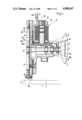
- FIG. 1 is a vertical cross-sectional view through the matrix pin print head
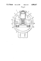
- FIG. 2 is an elevational front view of the matrix pin print head according to FIG. 1.
- a matrix pin print head 1 with an adjustable print pin guide 2 with an adjustable print pin guide 2.
- a print pin drive device group 3 and a print pin guide device group 5, disposed toward a print counter support 4, are provided with a casing 8 guiding the print pins 7.
- An electric lifting magnet 9, with a set screw 12 for the magnet core 13, is disposed in the area of the print pin guide device group 5.
- Said magnet core 13, together with a pin guide carrier 15, forms an adjustable magnetic discontinuity air gap 14, whereby the pin guide carrier 15 is movable back and forth between two fixedly adjustable positions.
- the electric lifting magnet 9 with its coil center axis 16 is disposed perpendicular to the center axis 17 of the matrix pin print head 1.
- Said center axis 17 is running in the print direction of the print pins.
- a magnet core 13, movable in a guide, is connected to a parallel adjustable pin guide carrier 15.
- the electric lifting magnet 9 can exhibit a core bushing 18.
- the magnet core 13, connected to the pin guide carrier 15, can be guided in the core bushing 18.
- a threaded nut 19 can be disposed at the side of the core bushing 18 disposed remote relative to the side of the center axis 17.
- a set screw 12 can be provided in the threaded nut 19 and can form with the magnet core 13 an adjustable magnetic discontinuity air gap 14 within the electric lifting magnet 9.
- a bent flat spring 23 can be disposed between the pin guide carrier 15 and the electric lifting magnet 9 fixed at the casing 8 of the print pin guide device group 5.
- the pin guide carrier 15 can form a substantially angular device component.
- Said angular device component can have the magnet core 13 attached to its first arm 15a and the pin guide stone 26 attached to its second arm 15b.
- the pin guide stone 26 can be attached to the second arm 15b and can be supported sideways in a guide 27, 28. Said guide 27, 28 can form the casing 8 of the print pin guide device component 5.
- the matrix pin print head 1 is equipped with an adjustable print pin guide 2.
- the matrix pin print head includes a print pin drive device group 3, which is only indicated in the drawings, and a print pin guide device group 5 disposed toward a print counter support 4, where the print pin guide device group 5 includes a slot 6 formed for print pins 7.
- the print pins 7, which for example form a slot 6 of nine or twelve print pins 7, are guided in a casing 8.
- An electric lifting magnet 9 is disposed in the region of the print pin guide device group 5 for the adjustable print pin guide 2.
- the print pin guide device group 5 is screwed with bolts 11, under insertion of adjustment sheet metal shims 10, onto a plate 3a of the print pin drive device group 3.
- the electric lifting magnet 9 includes an adjustment screw 12.
- the magnet core 13 is adjusted to a favorable magnetic discontinuity air gap 14 or, respectively, readjusted after assembly, with the adjustment screw 12.
- the print pin guide 2 is a pin guide carrier 15, which will be described in more detail below. This print pin guide 2 is moved back and forth through the electric lifting magnet 9 between two fixedly determined positions.
- the electric lifting magnet 9 with its coil center axis 16 is disposed perpendicular to the center axis 17 of the matrix pin print head 1, in particular for relatively short print pins 7 of a length of, for example, 27 mm, whereby the print pins 7 print essentially in the direction of this center axis 17 or, respectively, in parallel to the center axis 17.
- the guided magnet core 13 adjusts the pin guide carrier 15 with the print pin guide 2 parallel in the direction of the coil center axis 16 in such a way that the print pin guide 2 is adjusted perpendicular and not arcuate relative to the center axis 17.
- the electric lifting magnet 9 is furnished with a core bushing 18, and the magnet core 13, connected to the pin guide carrier 15, is slidingly guided in the core bushing 18.
- a threaded nut 19 is disposed at the side remote relative to the magnet core 13 at the electric lifting magnet 9.
- a set screw or adjustment screw 12 is provided in the threaded nut 19 such that the set screw 12 forms together with the magnet core 13 a magnetic discontinuity air gap 14 disposed about in the center of the guide bore length of the electric lifting magnet 9. This entering and incorporation of the magnetic discontinuity air gap 14 into the core bushing 18 saves stray fluxes such that less energy requirements exist at the electric connections 20 and 21.
- exciter coil 22 results in a very short casing 8 of the print pin guide device group 5 in case of relatively short print pins 7. In other words, the exciter coil 22 exhibits an extremely small diameter of a maximum of about 12 mm.
- the pin guide carrier 15 is maintained at a distance by way of a bent flat spring 23, which rests against the frame 24 for the exciter coil 22.
- the distance corresponds to the magnetic discontinuity air gap 14 or, respectively to the lifting distance for the print pin guide 2.
- the pin guide carrier 15 forms a substantially angular component with a first arm 15a, at which arm 15a the magnet core is attached with a rivet connection 25, and a second arm 15b, in which second arm 15b the pin guide stone 26 is attached.
- This second arm 15b is supported at the casing 8 of the print pin guide device group 5 in a respectively laterally formed guide 27 or, respectively, 28.
- the second arm 15b can be moved upward and downward depending on the size distance of the magnetic discontinuity air gap 14 between the guides 27 and 28, which in turn depends on the setting of the set screw or adjustment screw 12.
Landscapes
- Common Mechanisms (AREA)
- Impact Printers (AREA)
Applications Claiming Priority (2)
| Application Number | Priority Date | Filing Date | Title |
|---|---|---|---|
| EP87730139.0 | 1987-11-06 | ||
| EP87730139A EP0314851B1 (fr) | 1987-11-06 | 1987-11-06 | Imprimante à matrice d'aiguilles ayant un guidage réglable des aiguilles d'impression |
Publications (1)
| Publication Number | Publication Date |
|---|---|
| US4900167A true US4900167A (en) | 1990-02-13 |
Family
ID=8198373
Family Applications (1)
| Application Number | Title | Priority Date | Filing Date |
|---|---|---|---|
| US07/262,889 Expired - Fee Related US4900167A (en) | 1987-11-06 | 1988-10-25 | Matrix pin printer with adjustable print pin guide |
Country Status (5)
| Country | Link |
|---|---|
| US (1) | US4900167A (fr) |
| EP (1) | EP0314851B1 (fr) |
| JP (1) | JPH01154764A (fr) |
| AT (1) | ATE72545T1 (fr) |
| DE (1) | DE3776698D1 (fr) |
Cited By (1)
| Publication number | Priority date | Publication date | Assignee | Title |
|---|---|---|---|---|
| US9062570B2 (en) | 2010-06-25 | 2015-06-23 | Pierburg Gmbh | Infinitely variable pressure-control valve |
Citations (9)
| Publication number | Priority date | Publication date | Assignee | Title |
|---|---|---|---|---|
| DE224815C (fr) * | ||||
| US3882985A (en) * | 1973-07-23 | 1975-05-13 | Ncr Co | Tiltable matrix print head to permit viewing of the characters |
| DE2526233A1 (de) * | 1974-07-09 | 1976-01-29 | Zentronik Veb K | Mosaikdruckeinrichtung |
| US4284363A (en) * | 1979-07-30 | 1981-08-18 | International Business Machines Corp. | Data matrix print head |
| US4459051A (en) * | 1979-08-15 | 1984-07-10 | Canon Kabushiki Kaisha | Matrix printer |
| DE3412856A1 (de) * | 1984-04-03 | 1985-10-03 | Mannesmann AG, 4000 Düsseldorf | Matrixdruckkopf mit verstellbarer drucknadelfuehrung |
| DE3412854A1 (de) * | 1984-02-01 | 1985-10-03 | Mannesmann AG, 4000 Düsseldorf | Matrixdruckkopf mit verstellbarer drucknadelfuehrung |
| US4605323A (en) * | 1985-07-02 | 1986-08-12 | At&T Teletype Corporation | Dual quality wire matrix print head |
| US4640633A (en) * | 1984-03-22 | 1987-02-03 | Dh Technology, Inc. | High-speed wire print head with wire print position shift apparatus |
-
1987
- 1987-11-06 EP EP87730139A patent/EP0314851B1/fr not_active Expired - Lifetime
- 1987-11-06 DE DE8787730139T patent/DE3776698D1/de not_active Expired - Fee Related
- 1987-11-06 AT AT87730139T patent/ATE72545T1/de not_active IP Right Cessation
-
1988
- 1988-10-25 US US07/262,889 patent/US4900167A/en not_active Expired - Fee Related
- 1988-11-04 JP JP63279211A patent/JPH01154764A/ja active Pending
Patent Citations (9)
| Publication number | Priority date | Publication date | Assignee | Title |
|---|---|---|---|---|
| DE224815C (fr) * | ||||
| US3882985A (en) * | 1973-07-23 | 1975-05-13 | Ncr Co | Tiltable matrix print head to permit viewing of the characters |
| DE2526233A1 (de) * | 1974-07-09 | 1976-01-29 | Zentronik Veb K | Mosaikdruckeinrichtung |
| US4284363A (en) * | 1979-07-30 | 1981-08-18 | International Business Machines Corp. | Data matrix print head |
| US4459051A (en) * | 1979-08-15 | 1984-07-10 | Canon Kabushiki Kaisha | Matrix printer |
| DE3412854A1 (de) * | 1984-02-01 | 1985-10-03 | Mannesmann AG, 4000 Düsseldorf | Matrixdruckkopf mit verstellbarer drucknadelfuehrung |
| US4640633A (en) * | 1984-03-22 | 1987-02-03 | Dh Technology, Inc. | High-speed wire print head with wire print position shift apparatus |
| DE3412856A1 (de) * | 1984-04-03 | 1985-10-03 | Mannesmann AG, 4000 Düsseldorf | Matrixdruckkopf mit verstellbarer drucknadelfuehrung |
| US4605323A (en) * | 1985-07-02 | 1986-08-12 | At&T Teletype Corporation | Dual quality wire matrix print head |
Cited By (1)
| Publication number | Priority date | Publication date | Assignee | Title |
|---|---|---|---|---|
| US9062570B2 (en) | 2010-06-25 | 2015-06-23 | Pierburg Gmbh | Infinitely variable pressure-control valve |
Also Published As
| Publication number | Publication date |
|---|---|
| ATE72545T1 (de) | 1992-02-15 |
| EP0314851A1 (fr) | 1989-05-10 |
| EP0314851B1 (fr) | 1992-02-12 |
| DE3776698D1 (de) | 1992-03-26 |
| JPH01154764A (ja) | 1989-06-16 |
Similar Documents
| Publication | Publication Date | Title |
|---|---|---|
| US4750721A (en) | Movable table system | |
| US4674896A (en) | Printing mechanism for an impact matrix printer | |
| US4900167A (en) | Matrix pin printer with adjustable print pin guide | |
| RU1838069C (ru) | Направл ющее устройство машины дл контактной сварки кромок цилиндрической заготовки | |
| JP2523510B2 (ja) | 磁気デイスク装置 | |
| US4218148A (en) | Matrix printing cell and head assembly | |
| US3941052A (en) | Print hammer apparatus with angularly disposed mating hammer and pole faces to prevent contact bounce | |
| US4893858A (en) | Movable yoke-type lifting magnet device | |
| US4603985A (en) | Backstop and damping apparatus for actuator | |
| EP0109329A2 (fr) | Mécanisme d'entraînement équilibré pour tête d'impression | |
| KR20020096392A (ko) | 현가장치 시뮬레이터 | |
| SU1581557A1 (ru) | Устройство дл сборки деталей запрессовкой | |
| US4692043A (en) | Wire dot-printing head | |
| US5435656A (en) | Back stop structure for matrix pin print head | |
| GB2164001A (en) | Printing head for a dot line printer | |
| JP3093299B2 (ja) | 直動駆動装置 | |
| JP3763332B2 (ja) | ハンマ機構部およびそれを搭載した印字装置 | |
| EP0082334B1 (fr) | Mécanisme d'impression par marteau | |
| KR910000139Y1 (ko) | 프린터의 도트 매트릭스 헤드 | |
| JP3473793B2 (ja) | ドットラインプリンタのシャトル機構 | |
| US20080285086A1 (en) | System and method for an improved engraving of gravure cylinders | |
| JPS61123547A (ja) | ワイヤドツトプリンタヘツド | |
| JPH08145142A (ja) | ステージ | |
| JPH0742741Y2 (ja) | ドットラインプリンタの印字ヘッド | |
| SU1472190A1 (ru) | Устройство дл ломки проката |
Legal Events
| Date | Code | Title | Description |
|---|---|---|---|
| AS | Assignment |
Owner name: MANNESMANN AKTIENGESELLSCHAFT, MANNESMANNUFER 2, D Free format text: ASSIGNMENT OF ASSIGNORS INTEREST.;ASSIGNOR:KAUFMANN, CLEMENS;REEL/FRAME:004955/0367 Effective date: 19880930 Owner name: MANNESMANN AKTIENGESELLSCHAFT, MANNESMANNUFER 2, D Free format text: ASSIGNMENT OF ASSIGNORS INTEREST;ASSIGNOR:KAUFMANN, CLEMENS;REEL/FRAME:004955/0367 Effective date: 19880930 |
|
| FEPP | Fee payment procedure |
Free format text: PAYOR NUMBER ASSIGNED (ORIGINAL EVENT CODE: ASPN); ENTITY STATUS OF PATENT OWNER: LARGE ENTITY |
|
| REMI | Maintenance fee reminder mailed | ||
| LAPS | Lapse for failure to pay maintenance fees | ||
| FP | Lapsed due to failure to pay maintenance fee |
Effective date: 19940213 |
|
| STCH | Information on status: patent discontinuation |
Free format text: PATENT EXPIRED DUE TO NONPAYMENT OF MAINTENANCE FEES UNDER 37 CFR 1.362 |